
Abstract
Auto guide vehicle’s position deviation always appears in its walking process. Current edge approaches applied in the visual navigation field are difficult to meet the high-level requirements of complex environment in factories since they are easy to be affected by noise, which results in low measurement accuracy and unsteadiness. In order to avoid the defects of edge detection algorithm, an improved detection method based on image thinning and Hough transform is proposed to solve the problem of auto guide vehicle’s walking deviation. First, the image of lane line is preprocessed with gray processing, threshold segmentation, and mathematical morphology, and then, the refinement algorithm is employed to obtain the skeleton of the lane line, combined with Hough detection and line fitting, the equation of the guide line is generated, and finally, the value of auto guide vehicle’s walking deviation can be calculated. The experimental results show that the methodology we proposed can deal with non-ideal factors of the actual environment such as bright area, path breaks, and clutters on road, and extract the parameters of the guide line effectively, after which the value of auto guide vehicle’s walking deviation is obtained. This method is proved to be feasible for auto guide vehicle in indoor environment for visual navigation.
Introduction
Auto guide vehicle (AGV) is a kind of new intelligent transportation equipment which is widely used in modern manufacturing and processing, and warehousing material transportation. In the guidance modes of the AGV, the visual guidance has the advantages of good flexibility, strong anti-interference, high adaptability, and low cost. The real-time image processing system of the visual guidance AGV identifies the guide line (the centerline of lane line) and the special symbol preset in the working scene first. And then, the position deviation of the AGV, the angular deviation between the AGV’s forward direction and the guide line, as well as the distance deviation between AGV and the guide line are calculated successively. The motion controller controls the AGV to complete the task of path guiding at last.
The model of AGV’s visual system is shown in Figure 1. The AGV adopts a four-wheel structure, which means that left and right wheels are independent, while front and rear wheels are universal. The linear and steering motions of AGV are realized by differential drive. The camera is mounted directly in front of the AGV, and its optical axis is re-engaged in the AGV’s forward direction and at an angle to the ground. Compared with the way the camera is mounted on the vertical ground, the front-tilt installation of the camera does not require an auxiliary light source and can obtain a larger field of sight view, so as to collect more path information (such as special signs and obstacles). This paper aims at designing a deviation detection method which could meet the high-level requirements of complex environment in factories.
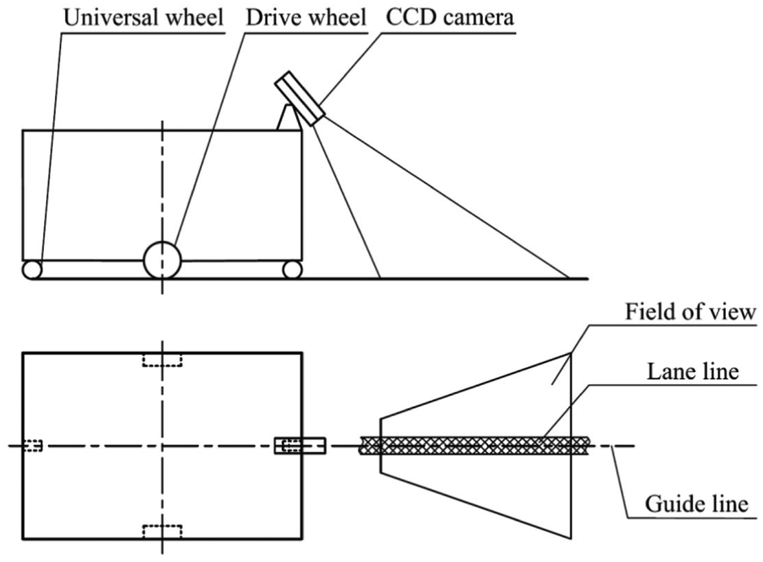
The model of AGV’s visual system.
Literature review and technical route
In recent years, many research works, which employ computer vision and image processing techniques, have been proposed for detection of lane line and AGV’s deviation. However, there are some unresolved issues even though the technology in this field is mature.
Literature review
The recognition methods of the guide line based on computer vision technology are mainly divided into three categories: method based on features,1–3 method based on regions,4,5 and method based on templates. 6 The feature-based detection technique locates the guide line in the image according to the underlying features of the path, the edges, and the color of the guide line. Taking Yang and He’s 7 work, for example, they studied the lane line detection method based on RGB. This technique is susceptible to noise or other factors. 8 The region-based detection technique detects the target in a small area based on the approximate position of the guide line. This method can effectively remove most of the interference information in the image of the road. For example, Amol Borkar and colleagues9–11 divided the image into left and right parts in the lane line detection and then detected the left lane line in the left part and the right lane line in the right part. However, this method cannot handle the situation that several obstacles appear on the pavement or lane lines are in the middle of the road. The template-based detection technique uses only a few parameters to represent the lane line.12–14 Assuming that the shape of the lane line can be represented by a straight line or a curve, this detection technique estimates these template parameters during the detection process to complete the identification of the lane line. Compared with feature-based detection technique and region-based detection technique, template-based detection technique is more effective to handle abnormalities such as noise or data loss.
Most of the lane lines used for AGV can be considered as straight lines. General technical methodologies for estimating template parameters are maximum likelihood method, 15 Hough transformation, 16 and chi-square fitting, 17 among which Hough detection is the most commonly used because it is not sensitive to noise. Currently, edge detection algorithm mainly includes difference operator, Roberts operator, Laplace operator, Laplacian of Gaussian operator, Prewitt operator, Sobel operator, Kirsch operator, and Canny edge detector.18–20 The Canny edge detector has better anti-noise effect, and it can reduce the occurrence rate of repeated edges in complex image.
Existing problem and technical route
The edges of lane line are two parallel lines in the three-dimensional (3D) viewing angle while two intersecting lines in the two-dimensional (2D) viewing angle. The edge lines obtained by the edge detection are intersected, so the parameters of the guide line cannot be directly obtained. The images obtained by edge detection include not only the left and right edge lines but also noise which will affect the extraction of the parameters. Therefore, in the estimation process of template parameters of the guide line, edge detection algorithm has a large amount of calculation and low accuracy, which makes it difficult to adapt to the complex environmental disturbances of the factory, as well as to accurately acquire the position deviation of the AGV.
In order to avoid the defects of edge detection algorithm, this paper proposes a new method, which innovatively introduces the refinement algorithm into the field of AGV’s visual navigation. The refinement algorithm is implemented to obtain the skeleton of the lane line, combined with Hough detection and line fitting, the equation of the guide line is obtained, and then, the value of AGV’s walking deviation can be calculated. The identification process of the AGV’s visual guide line is shown in Figure 2. With the parameters extracted, the AGV’s motion controller can eventually complete the correcting and navigation tasks. The detailed recognition algorithms of guide line and their implementations are explained in section “Recognition algorithm and its implementation.” Section “Experiments and results” includes the experiments carried on together with the results and the conclusion is given in the last part.
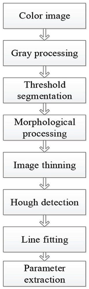
The identification process of the AGV’s visual guide line.
Recognition algorithm and its implementation
Before the process of image thinning, the image preprocessing including gray processing, threshold segmentation, and the operation of mathematical morphology is necessary. The camera acquires the RGB information of the lane line set for AGV, and the visual system converts the RGB color model into the HSV color model to obtain the grayscale image. Subsequently, the clear binary features of the lane line can be obtained by threshold segmentation and morphological processing.
Next, combined with the operation of image thinning, Hough detection, and line fitting, the mathematical equation of the guide line is generated. Finally, the angular deviation, as well as the distance deviation, will be figured out.
Image preprocessing
The image preprocessing should minimize the interference of irrelevant information in the image to the guidance feature and minimize the computation of subsequent image detection and recognition simultaneously. The gray processing can transform the color image of the three channels (RGB) into a single-channel grayscale image, which will greatly simplify the computation and accelerating the speed of the following algorithm.
First, convert the color image (Figure 3(a)) into a grayscale image (Figure 3(b)). The color image is represented by the RGB model, and each pixel is composed of three components of red R, green G, and blue B. The gray processing of RGB image is, in layman’s terms, the re-assignment of three components’ values of RGB image. The most common methods are given as follows:
1. Components method. The value of one component of three RGB components is used as the gray value of the pixel point, which means

2. Maximum value method, which means

3. Mean value method, which means

4. Weighting method. Three components in RGB are given different weights, and the value obtained by summation is taken as the gray value of the pixel point, which means

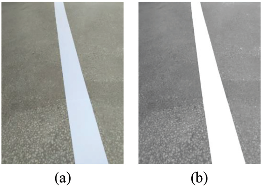
The contrast between the color image and the grayscale image: (a) original image and (b) grayscale image.
The human eye is most sensitive to green and least sensitive to blue. In equation (4), the weight of green is more than 50%, while the weight of blue is less, thus equation (4) is also known as the famous psychological gray formula. In this paper, the fourth method is selected and reassigned the value of Gray to R, G, and B. The gray image can be obtained by equation (5)

In order to obtain a binary image with a black background and white feature area, the lane line needs to be segmented from the background. The threshold segmentation algorithm is able to segment such scenes well with simple calculation and high efficiency. During the actual driving process of AGV, environmental factors such as uneven illumination, may result in changes of the image. Therefore, the threshold segmentation algorithm to be adopted should automatically adjust the segmentation threshold according to the environment. Such algorithms include iterative method and maximum interclass variance method, and the latter is also called Otsu.21,22
In an indoor environment, the floor may be smooth and several lights are on. In this case, the different results processed by iterative method and Otsu method are shown in Figure 4, where the left image shows the above situation. The optimal threshold for the iterative method is 108, and the Otsu method is 128. In the middle image (the result processed by the iterative method), a large block of noise that interferes with the lane line area exists, but a more satisfactory result is shown in the right image (the result processed by the Otsu method).
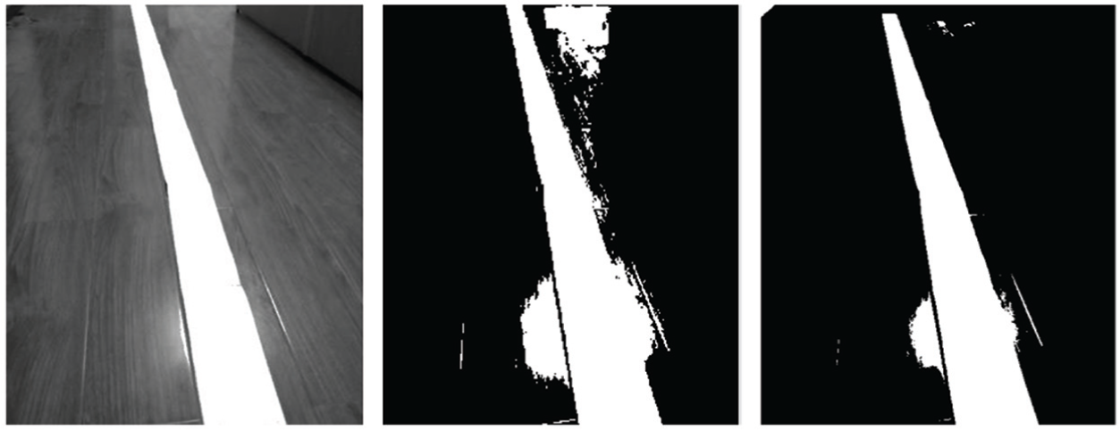
The different results processed by the iterative method and the Otsu method.
In this paper, the Otsu method is applied to binarize the grayscale images. Suppose the gray level of a digital image is
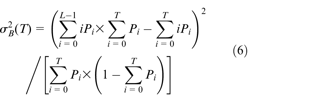
where

Even after image segmentation, the image of lane line may have some abnormal information such as holes, bumps, and cracks due to the defects in the ground environment. Morphological processing can optimize the segmented image. Image expansion can connect the discontinuous boundary and the target areas. Image corrosion can effectively eliminate the connection between the target area’s boundary and the non-target area’s boundary, making the edge positioning more accurate and eliminating subtle noise.
Suppose A is the original image and B are specific morphological structural elements. The expansion of A with B is defined as

where
The corrosion operation of A with B is defined as

Take B to iterate through image A. The “AND” operation is performed on B and its corresponding region in image A. If the result is 1, the value of the pixel in image A corresponding to the origin position of template B is set to 1, otherwise set to 0.
The open operation of A with B is defined as

The closed operation of A with B is defined as

After the threshold segmentation, a circular template is applied to the image’s opening operation (eliminate the bulge) and closing operation (smooth the edges of the outline). The processed image is shown in Figure 5(b), from which we can see that the flaws left by image segmentation are effectively compensated.
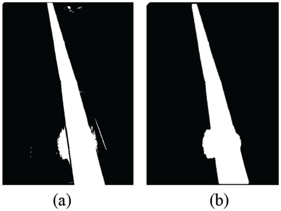
The contrast between before and after the operation of morphology: (a) image obtained by image segmentation and (b) image with the operation of morphology.
Refinement algorithm
In the field of binary image processing, refinement is a very important processing step. Refinement is to represent a certain area with a (or a set of) curve. The thinning algorithm is an algorithm that repeatedly strips the boundary pixels of the binary image, especially the pixels at the change of 0 ∼ 1, but must maintain the connectivity of the target and eventually form a single-pixel-wide image skeleton.
Refinement algorithm includes iterative method and non-iterative method. The iterative method is divided into serial refinement algorithm and parallel refinement algorithm. As to the serial algorithm, whether the pixel is deleted or not depends not only on the result of the previous iteration but also on the distribution of the processed pixels in this iteration. For the parallel algorithm, whether the pixel is deleted or not is independent on the order of the pixel values and depends only on the results of the previous iteration. The existing iterative algorithms have their own advantages and disadvantages. The Zhang-Suen algorithm is a typical parallel refinement algorithm. Its most prominent advantage is that it can be consistent with the original image more accurately after refinement with fewer iterations and faster running speed for straight lines, T-line crossings, and corners.
The Zhang-Suen algorithm carries on an arithmetic logic operation on the eight neighborhoods of the object’s contour pixels (former attractions) and determines whether the pixel will be deleted according to the operation result. For any pixel point
Step 1. If the eight neighborhoods of the pixel point


where
Step 2. If


Above steps are repeated until that no pixels can be deleted in the target image and then the refinement process terminates. The skeleton of the lane line processed by image thinning is shown in Figure 7.
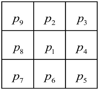
Pixel point
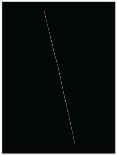
The skeleton of the lane line which was processed by image thinning.
Hough transform and perspective transformation
Most of the lane lines are linear. Since the Hough transform can transform the problem of searching a line in the image plane into the problem of searching the peak point in the parameter space, the Hough transform is selected to realize the connection and identification of the guide line.
The Hough transform converts the curve into point in the parameter space according to the duality of point and line, and detects the characteristics of the given curve by a voting algorithm.23,24 A point on a straight line in the Euclidean space is a sinusoid in the parameter space. A plurality of points on the same straight line in the Euclidean space corresponds to sinusoidal clusters in the parameter space, and those curve clusters intersect at a point which is called the peak point. The peak point in the parameter space represents a straight line in the Euclidean space. Figure 8 shows this transformation relationship where point
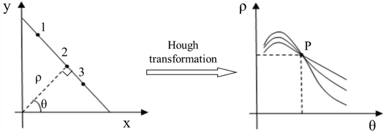
Schematic diagram of the Hough transform, which converts problem of searching a line in the image plane into the problem of searching the peak point in the parameter space.
A line in the Euclidean space can be expressed as

In the process of detecting the parameters of AGV’s guide line,

where
The steps to detect a line using the Hough transform are listed as follows:
1. Discretize the parameters
2. For each of the former attractions

3. Find the point with the largest cumulative number of cumulative matrix in the parameter space and record it, set a threshold for cumulative number, and find the peak point of the parameter space. Substituting the point
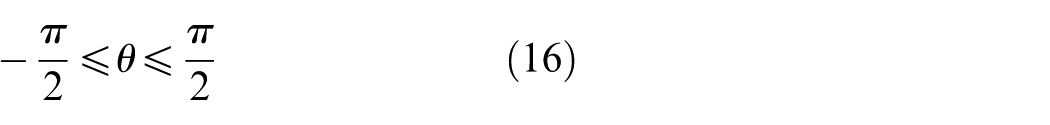
The obtained refinement image is detected by the Hough detection algorithm, and a continuous line is fitted. Figure 9 shows the result of Hough detection and line fitting.
The results of Hough detection and line fitting: (a) result of Hough detection and (b) result of line fitting.
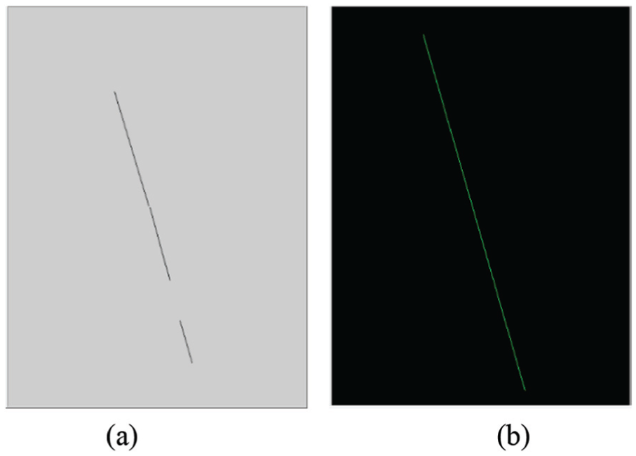
The fitted line requires a perspective transformation to represent the actual parameters. In the previous research,
25
the homography matrix
Parameters and deviation
After the operation of image thinning, Hough detection, and perspective transformation, the mathematical equation can be rewritten as

where parameters
Owing to the camera is installed in the front of the AGV, the mid-line of the obtained image is AGV’s instantaneous forward direction. AGV’s angular deviation can be defined as the angle between the guide line and the mid-line of image, and the distance deviation in image can be defined as the vertical distance between the center of the image and the guide line. Figure 10 is a schematic diagram which shows such definition.
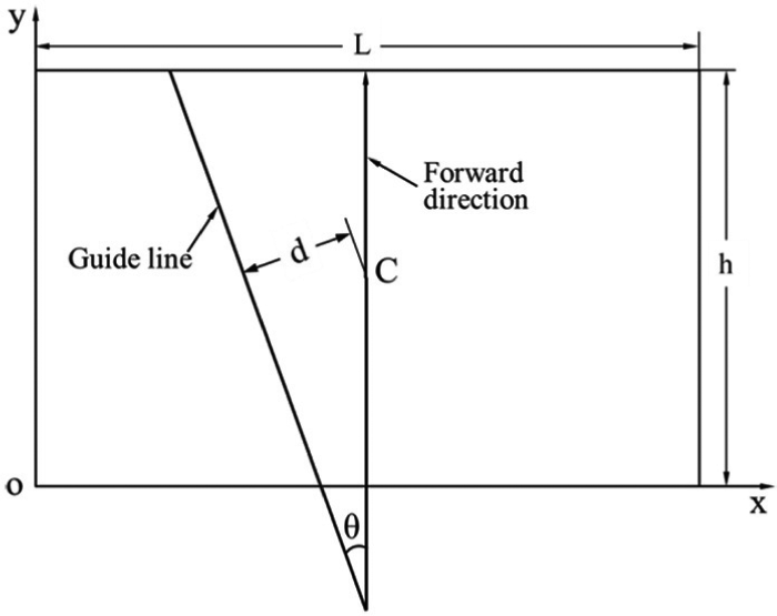
Schematic diagram of AGV’ walking deviation.
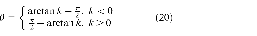
The angular deviation
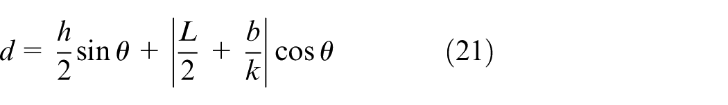
The distance deviation in image
The real distance deviation
Experiments and results
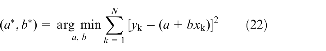
In order to verify the validity of the proposed method in this paper, parameters of guide line in three different cases were extracted. Meanwhile, the traditional edge extraction algorithm in the field of visual navigation for AGV was also used as a contrast to verify the superiority of the method we proposed in this paper. For edge detection algorithm, the centerline is fitted with the least squares method, and its parameters
Considering the concrete noise in AGV’s complex working environment, three case images shown in Figure 11(a) are studied: in the first image, there is an obvious bright area caused by lighting equipment; in the second image, the lane line breaks; in the third image, a certain amount of clutters in the surrounding environment exist. As shown in the preprocessed images (Figure 11(b)), the interference of irrelevant information in the image to the guidance feature was minimized, which would minimize the computation of subsequent image detection and recognition. Next, image thinning combined with Hough detection (T-H) and Canny/Sobel detector combined with the least squares method (C-L/S-L) were performed to obtain the fitted lines, respectively.
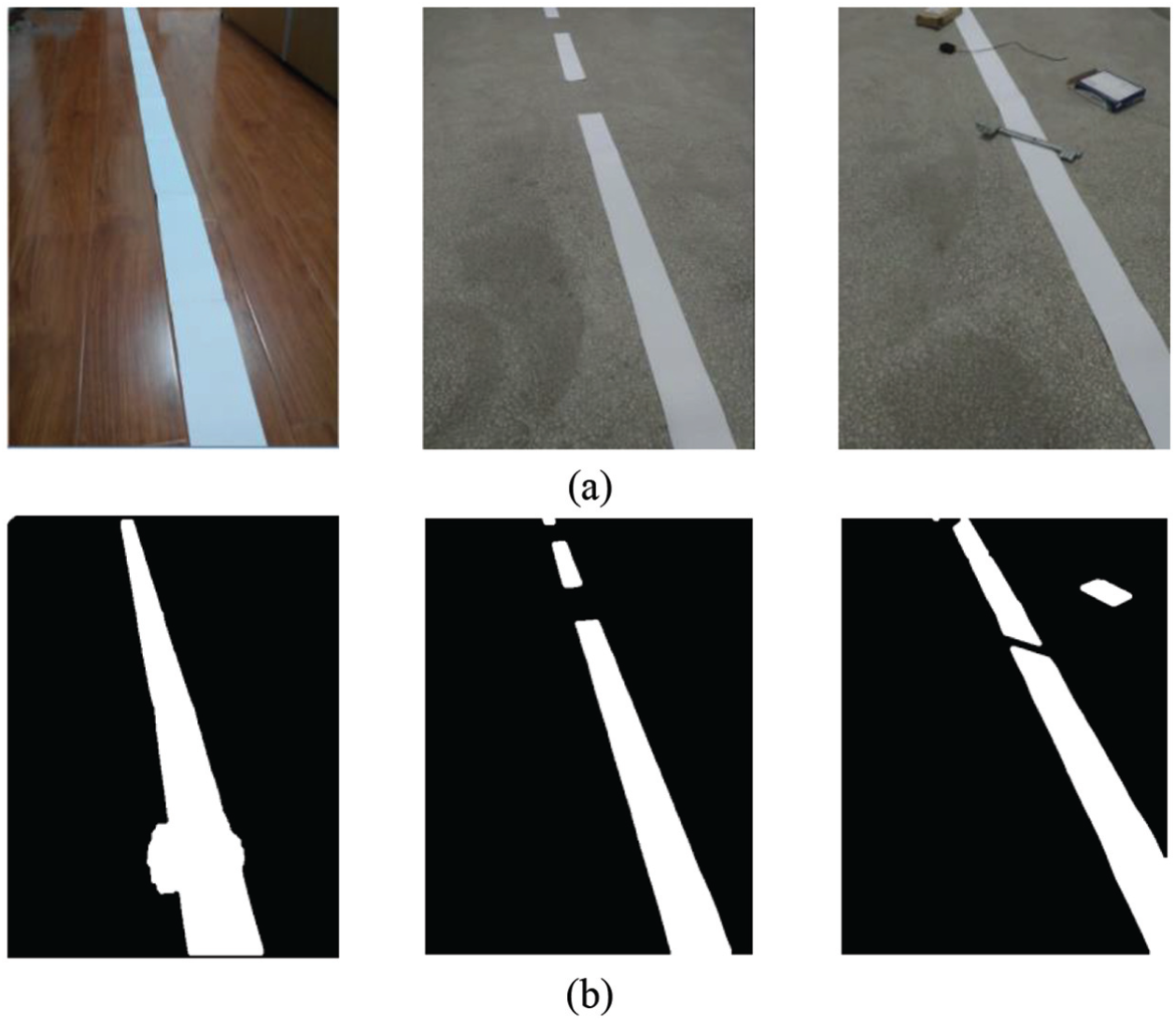
The noise of actual environment and the preprocessed images: (a) bright area, path breaks, and clutters in AGV’s actual working environment and (b) desirable images processed by image preprocessing.
On one hand, as for the preprocessed images, continuous lines were fitted after the refinement and the Hough detection, which were the green lines in Figure 12. During the process of line fitting, a threshold of the length of line segments had been set. All line segments whose length was less than the threshold would be thrown away. The experimental results show that the proposed detection method of guide line can deal with some non-ideal factors of the actual image and extract the parameters of the guide line effectively.
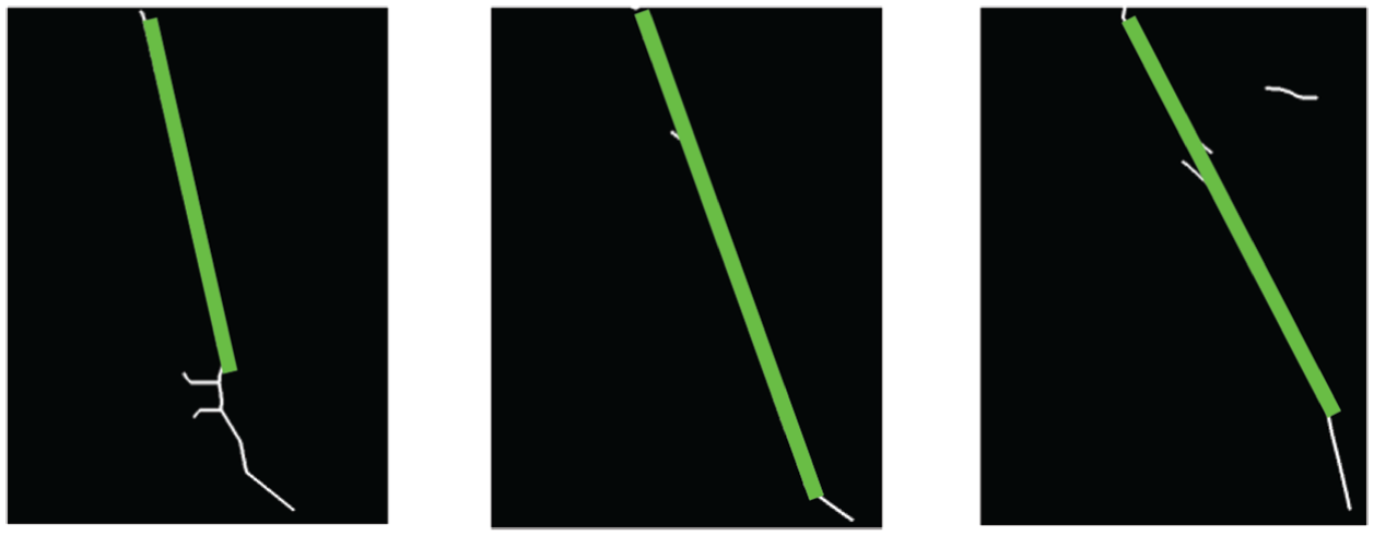
The results of refinement, Hough detection, and line fitting.
On the other hand, for the preprocessed images, the images of edges using canny detector are shown in Figure 13(a), from which we could observe clear edge lines, even the edges of noise. And then, with the least squares method, continuous lines shown in Figure 13(b) (the green straight lines) were fitted. As to path breaks, the fitted line is in line with the actual situation, while as to bright area and clutters, the fitted lines are off normal. And, the more noise such as bright area and clutters, the greater the error.
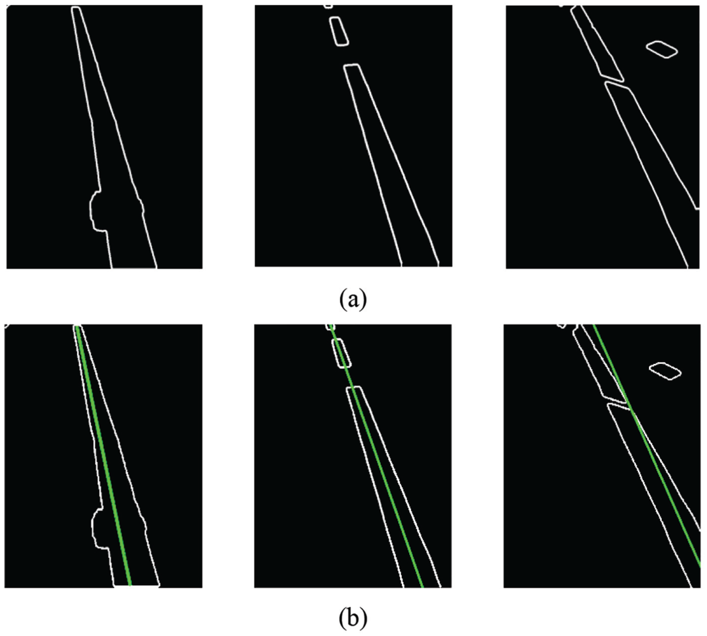
The results of Canny detector combined with the least squares method: (a) edges of the preprocessed images by using canny detector and (b) fitted lines of the edges with the least squares method.
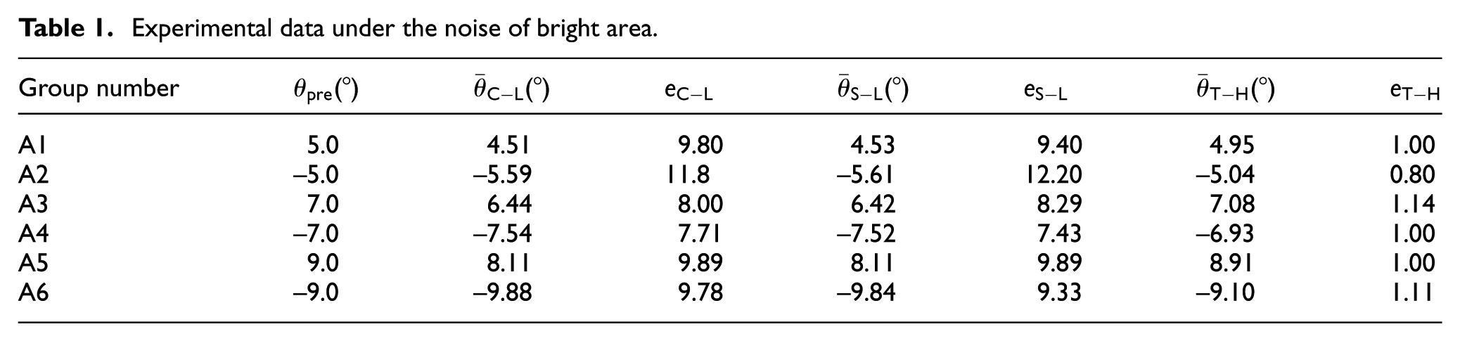
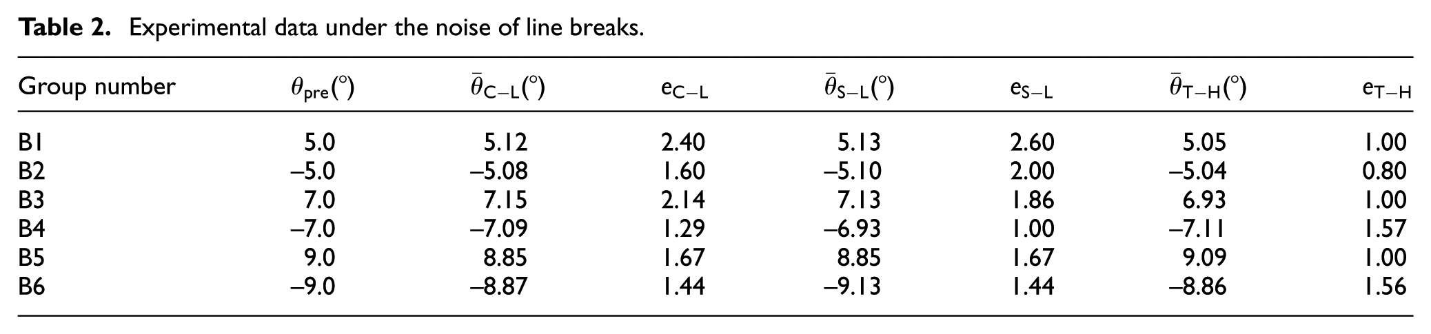
After the operation of perspective transformation, we obtained experimental data about the angular deviation of the guide line. Tables 1–3 show the value of angular deviation calculated according to equation (20). In total, 10 measurements were performed in each group, and

Experimental data under the noise of bright area.
Experimental data under the noise of line breaks.
Experimental data under the noise of clusters.
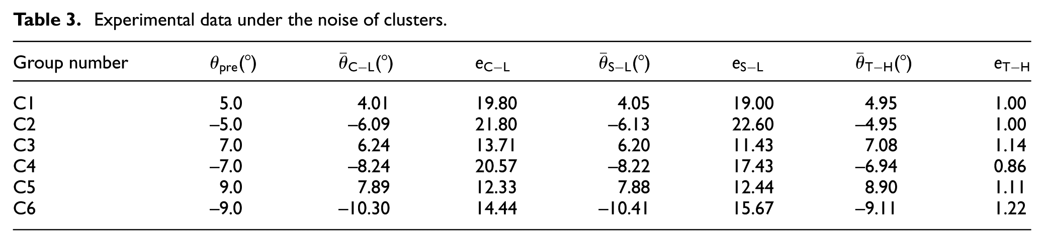
According to the statistical data, the error rate
Compared with the edge detector, we can find that the method we proposed in this paper is easier and more efficient to extract the deviation parameters, meaning that the refinement algorithm combined with Hough transform is able to get the parameters of the guide line and remove the influence on the identification of the guide line effectively, which is affected by factors such as bright area, path breaks, and clutters on road.
Conclusion
This paper presents a recognition method of AGV’s visual guide path and the detection method of AGV’s walking deviation. With the gray processing, threshold segmentation, and morphological processing, as well as the implementation of thinning algorithm and Hough transform, a new method of extracting the parameters of AGV’s guide line is proposed. The proposed method can deal with non-ideal factors of the actual environment such as bright area, path breaks, and clutters on road effectively. Compared with the Canny detector and Sobel detector, the new method performs with higher accuracy and better stability than other comparisons. The experimental results on the actual road show that this method can be used to extract the parameters of the guide line and to get the value of AGV’s walking deviation accurately and effectively. This method is proved to be suitable for visual navigation of AGV under indoor environment.
Footnotes
Declaration of conflicting interests
The author(s) declared no potential conflicts of interest with respect to the research, authorship, and/or publication of this article.
Funding
This work is supported by the National Key R&D Program of China through Grant No. 2018YFC1407405. This work is also supported by Science and Technology Foundation of the State Grid Corporation of China.