
Abstract
Eddy current testing technique is being utilized in engineering, such as in nuclear steam pipe, aircraft and gas/oil pipeline, due to its sensitivity to small cracks and subsurface defects, immediate results, environmental friendliness, and use in examining complex sizes and shapes of substances. However, the lift-off noise due to irregular inspected materials surface, varying coating thicknesses, or movement of transducers extremely limits the implementation of eddy current testing in a non-disastrous testing which impacts the measure of defect depth on the conductive material. In this paper, a study on hybrid giant magneto-resistance/infrared probe is proposed to minimize the influence of lift-off for detecting the depth defect. The giant magneto-resistance reads the magnetic field which reflects any defect inside the pipeline, and infrared sensors read the movement of each giant magneto-resistance inside the pipeline. The error compensation technique depends on Mamdani fuzzy which examines the interaction that exists between the peak value of giant magneto-resistance and the infrared sensor signal. The eddy current testing inspection system includes details of the giant magneto-resistance–eddy current probe design and instrumentation of the error compensation technique. The measurement method is based on alternating current supply with 30 kHz frequency to ensure that the crack signals are clearly displayed. The proposed method is verified experimentally, and the result shows that the impact of lift-off noise is highly reduced in the eddy current testing technique and enhances the sensor accuracy. The depth defect error caused by 1 mm lift-off is reduced to 7.20%.
Introduction
Eddy current testing (ECT) techniques are widely used in many industrial sectors to examine and estimate the integrity of conductive materials due to their high sensitivity and robustness. 1 ECT techniques are utilized in applications such as in detection of defects on a conductive sample, measurement of sample thickness, estimating coating thickness on pipelines, and measuring properties of materials like electrical conductivity and permeability. The most recent research presents the magneto-resistive sensors in ECT techniques due to their linear response which makes them suitable for detecting low-amplitude electromagnetic field when a low frequency is applied.2,3 They have been used successfully for detecting subsurface cracks under riveted structures,4–6 and for concurrent investigation of materials at various depths. This is the enormous feature of utilizing sensors relative to coils. 7
However, ECT with magnetic field measurement method has equally been obstructed by some known issues, and lift-off noise is one of the main factors affecting ECT.8–10 The lift-off can be generated from irregular specimen surface, varying coating thicknesses, or vibration of the ECT probe during the scan of a material.
Fan et al., 11 investigated the influence of a bobbin probe’s radial offset on the ECT. It is found that the radial offset leads to a non-uniform distribution of eddy current density, and the sensor signal changes and the measurement accuracy is degraded. A range of techniques, such as probe structure, 12 detection principle, 6 and signal processing 13 has been investigated by many researchers. Many designs have been established to compensate the effect of variation on ECT signals, such as choosing an appropriate probe design of a particular excitation and receiving coil.14,15 Yin and Xu 16 introduced a new design composed of a triple coil sensor operating in multi-frequency to infer thickness from a novel index, termed as the peak frequency. Mathematically, it was found that the zero-crossing frequency (peak frequency) decreases with increase in the lift-off, while the difference in their peak frequencies is linearly proportional to sample thickness; nevertheless, it is resistant to lift-off differences. The outcome of this study reflected that the employed technique is stronger than lift-off variations. Lu et al. 17 proposed a simple design containing one pair of coil in a less complicated structure. A novel index termed (compensated peak frequency acquired measured multi-frequency) was developed to avoid the effect of lift-off and link the thickness of a metallic plate. The experimental results of thickness measurements showed the accuracy of this method at various lift-offs to be within 2%. The same design was used by Lu et al., 14 but another index termed compensated zero crossing frequency was used to reduce the impact of lift-off in a magnetic plate. The permeability can be predicted from Dodd and Deeds approach based on the relation between zero-crossing frequency and the permeability. The results showed that the permeability error caused by the lift-off was decreased to 7.5%.
Wu et al. 18 proposed an air-core coil for thickness measurement which is immune to the lift-off effect by using the phase signature of inductance change when an air-core coil is next to a plate sample. The results proved the effectiveness of the postulated technique. A model-based inversion technique was examined relative to lift-off reduction; 19 the efficiency was determined and verified using Monte Carlo analysis. The results from the experiments showed the value of thickness and conductivity to be within 2.5%. Dziczkowski developed a new method to measure the reduction in the impact of lift-off from EC measurement of conductivity. The method was based on solving two equations in two unknown conductivity and lift-off by measuring the change in the resistance and inductance of the coil. A dual-stage technique utilizing normalization and two references signal to eliminate the lift-off issue with pulsed eddy current (PEC) technique was proposed by Tian et al. 20 The method can be used for measurement of thickness coating. The reduction in the impact of lift-off can be accomplished at most during subsurface slot inspection. Yu et al. 21 proposed an approach based on the slope obtained from the linearize plot of lift-off and a peak value of the difference signal to determine the defect depth. The experiment results approved that the method reduced the effect of lift-off in eddy current technique when compared to the traditional method. Thus, it can be utilized in the characterization of the defect depth in the conductive material. Cordier et al. 22 proposed magnetic sensors to improve the accurate of tube axis alignment. The theoretically predicted high was around 10–50 µm. Vasic et al. 23 compensated the wobble effect of the coil and applied corrections to the sampled signals, thereby obtaining accurate measurements. Ribertro et al. 24 introduced a mathematical algorithm to compensate the impact of lift-off which depends on the dimensional frequency of output signal, lift-off, and its alternative structure (deconvolution) within the spatial domain. The spatial spectra functional group of the filter was evaluated. The measurement at three various lift-offs for the same defect showed an exponential amplitude decrease with increased lift-off for an inductive probe and for a giant magneto-resistance (GMR) probe. The acquired results illustrated the feasibility of a reverse deconvolution of the filtering influence. The artificial intelligence in ECT was developed to reduce the error due to lift-off in assessing the depth defect from the peak amplitude of the GMR output signal for carbon steel pipe. Previously, the output signal characteristics had been used in the prediction of depth flaw in conductive substances.25–27 Depending on the consideration that the signal amplitude declines with increasing lift-off, this is imperative because the lift-off difference is inevitable in several applications. An error compensation method that uses a fuzzy inference system (FIS; Mamdani type fuzzy) was established; this can be compensated due to its difference in the signal amplitude.
In recent years, many probe designs have been carried out to improve the ECT accuracy when choosing an appropriate probe design of excitation and receiving coils besides using a magnetic sensor as a detector.12,14,22 Yuan et al. 8 designed a bobbin coil (BC) probe with tunnel-magnetoresistance (TMR) sensor array to inspect the longitudinal crack inside the aluminium pipe with the dimension 5 mm, 0.5 mm, and 30 mm for depth, width, and length, respectively. The depth defect was estimated by the characteristic signal. The effect of lift-off on the sensitivity of the bobbin probe was analysed using finite element method (FEM), and the result showed that the sensitivity of the bobbin probe decreased sharply as the lift-off increases. When the lift-off between the probe and the wall pipe is greater than 6 mm, no obvious perturbation was observed in the magnetic field. A probe structure that integrates the eddy current coil and two GMR sensors have been introduced by Sasi et al. 4 to study the detection sensitivity of deep defect >5 mm under different lift-off on 8-mm-thick AISI type 316 stainless steel plate. The results of the measured amplitude of the radial magnetic field for 6 mm depth defect under lift-offs 0.5, 1.0, 3.0, and 6.0 mm illustrated that the detectability of amplitude was limited to 1.0 mm lift-off. The previous studies focused on early detection of a defect; however, depth estimation of the defect through amplitude signal is affected by depth defect and lift-off.
In this study, a GMR-BC probe was proposed which consists of a BC and integrated GMR and infrared (IR) sensors. The enhancement of GMR-BC probe is based on a hybrid system (GMR sensors and IR sensors). The GMR sensors array was employed to estimate the induced fields, and an array of IR sensors were used to measure the changes in the lift-off. The peak amplitude of the GMR measurement was compared to the peak amplitude of IR sensor to compensate the error of lift-off using the error compensation method. This was achieved by using Mamdani type fuzzy to minimize the lift-off influence in the detection of depth flaw and unveil the error generated by the lift-off variation in 55 mm carbon steel pipe.
The proposed error compensation technique
The overall proposed error compensation technique is shown in Figure 1. This technique utilized a single ECT probe managed in two different processes: first, to establish a series of detection channels, and the other is to create a set of lift-off measurement channels. Because of the relationship between the two measurements through Mamdani type fuzzy, the depth defect parameter can be quantitatively evaluated by the degree of the peak amplitude of the GMR signal on the EC detection. By using the Mamdani fuzzy type approach, the effect of the lift-off can be strongly reduced. When the GMR-BC is excited using an alternating current, the reference signal can be achieved under 0 mm lift-off; thereafter, the detection signals under the different lift-off for carbon steel pipe with different depth defect can be obtained using the GMR sensor; the interaction between the peak value of a depth of defect and lift-off can be acquired; then determining a set of fuzzy rules and the inputs can be fuzzified through the transformation of crisp input to a linguistic parameter using the MFs embedded in a fuzzy knowledge database. The fuzzified inputs can be joined based on fuzzy rules to implement a rule strength that comprises the fuzzy IF-THEN rules in converting the fuzzy input into fuzzy output. The result of the rule can be determined through the integration of the rule strength and output membership function (implication), followed by the integration of the results to attain an output distribution (aggregation). Finally, the defuzzification step is applied by utilizing the centroid method to get the new crisp value which presents the compensated signal output; the defect depth can be obtained through the relation between the peak amplitude and the depth of defect.
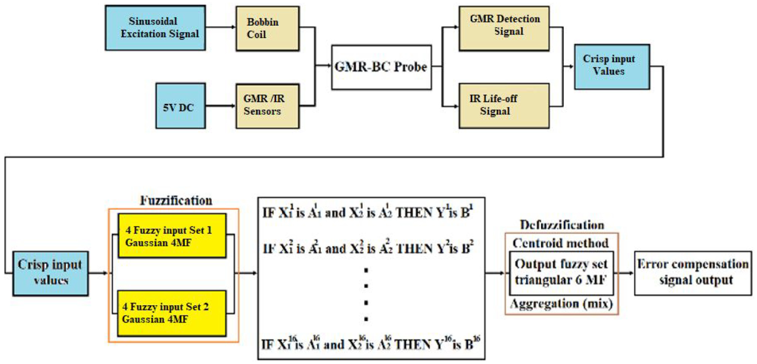
The proposed error compensation technique.
Combination of GMR/IR sensors
The proposed GMR-BC probe is composed of an array of GMR sensors, an array of IR sensors, and the excitation BC as shown in Figure 2. In eddy current, testing is critical to control the lift-off as the signal amplitude is directly influenced by lift-off variations. 28 Probe offset along the radial direction is common during the scanning. In the proposed ECT probe, two possible offsets along x and y-axes may cause different lift-offs between the array of GMR sensors and wall pipe. Consequently, it will affect the measurement of depth. In the case of using the 51 mm diameter probe, when the probe is in the centre (normal condition), the lift-off between the GMR sensors and the wall pipe will be 2 mm as shown in Figure 2(a). However, when the probe offset is along x-axes in the direction of GMR3 and GMR6, the lift-off for GMR1 = 2 mm, GMR2 = 4 mm, GMR3 = 4 mm, GMR4 = 2 mm, GMR5 = 0 mm, and GMR6 = 0 mm, as shown in Figure 2(b). This condition can result in the reduction of detection performance and/or false performance detection. This is true for the automated inspections with eddy current array technology where the lift-off cannot be mechanically compensated for at individual sensor positions.
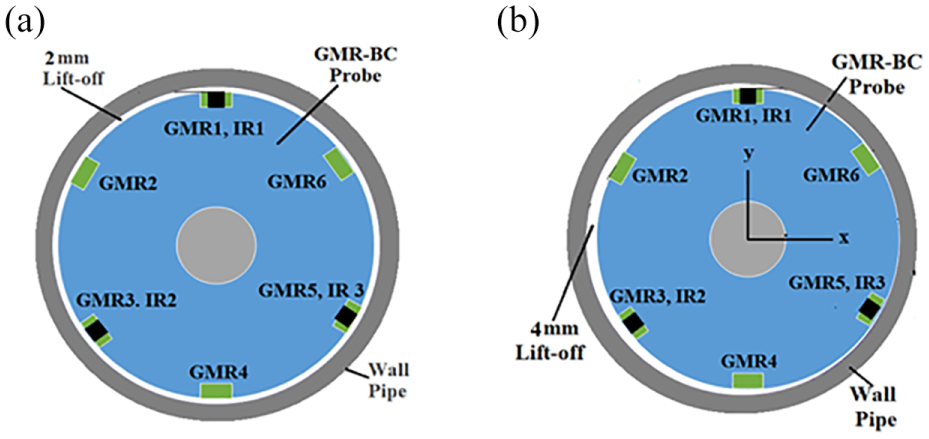
(a) The probe is in the centre (normal condition) and (b) probe eccentricity along x axes (change distance of lift-off).
Fuzzy error compensation
The MATLAB/Simulink Toolbox was utilized to simulate the GMR-BC probe input signals, the FIS, and the resulted output signal. The Simulink fuzzy error compensation technique model was developed as shown in Figure 3. The diagram model consists of three parts which are utilized for the error compensation technique. The first part is the two output of GMR-BC probe (GMR and IR sensors voltage signals) which are set as inputs on the Simulink. The second is the FIS process and feedback; the fuzzy block setting is exported to the file and workspace for simulation in Simulink. The feedback and error compensation will be processed according to the output signal from fuzzy logic. The output signal from fuzzy will be run through the error compensation equation in the signal block, and it will generate feedback to the error block, with output display as the last part.
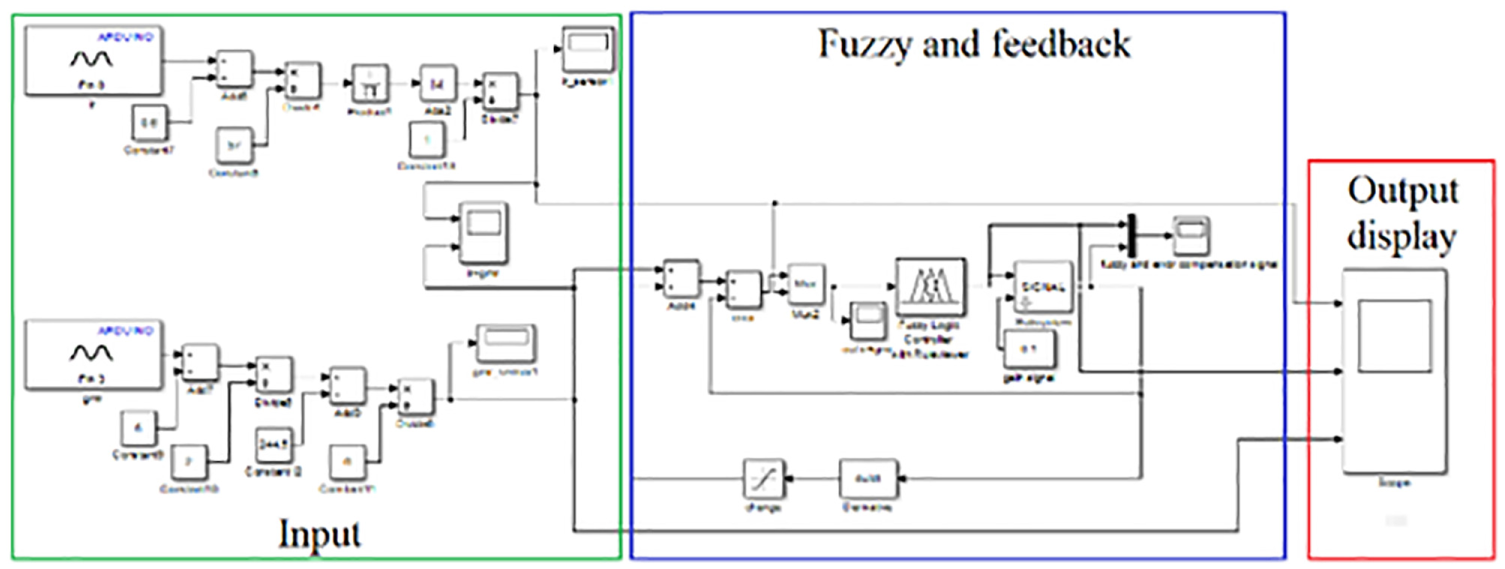
Error compensation technique using MATLAB Simulink.
Therefore, the trained fuzzy logic engines are employed to forecast the crack data; it supports the obtained characteristics or combined characteristics when the membership degree of the input data from input fuzzy data have been defined. The Internal Block Function in FIS is shown in Figure 4.
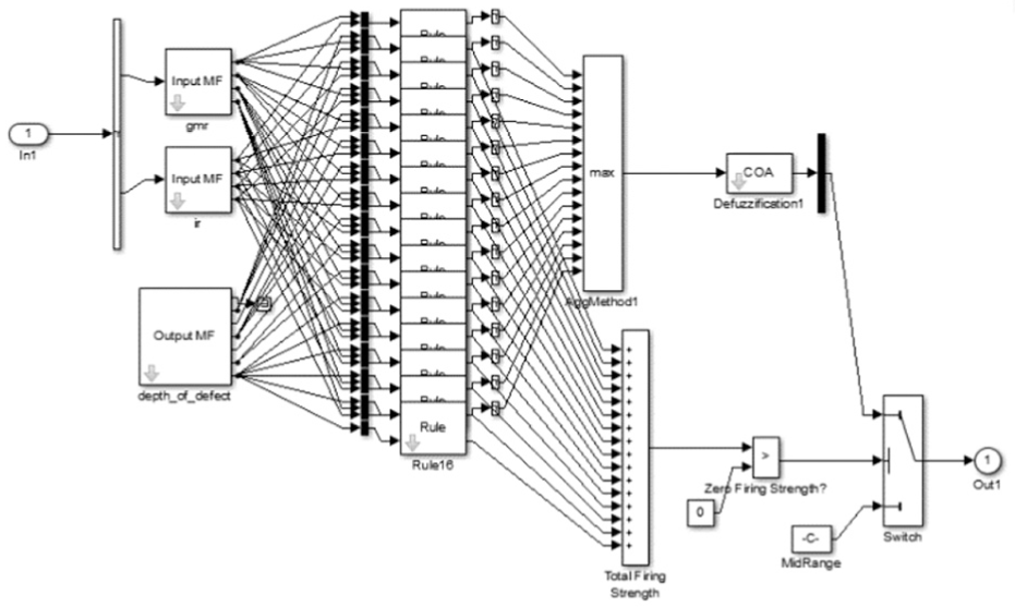
Internal block function of fuzzy inference system (FIS).
In a FIS, the fuzzy inference engine is employed in the building of fuzzy rules. The built rules depend on the system requirements. After its assessment, their membership function is evaluated based on the output data (consequent). Fuzzy rules are enlisted in IF-THEN lingual condemnations, which explain the relationship that exists within the output and input. In all, 16 rules are arranged based on a rule editor for depth measurement and lift-off, as shown in Table 1.
Rule base of Mamdani-type FIS.

GMR: giant magneto-resistance; IR: infrared.
Experimental setup
The effect on sensitivity detection of the GMR-BC probe under varying lift-off conditions has been determined experimentally. Figure 5 shows overall experimental set-up which consists of power system, GMR-BC probe design, electro-pneumatic system, pipeline sample with an artificial defect, data acquisition system and signal processing MATLAB R2015b software.
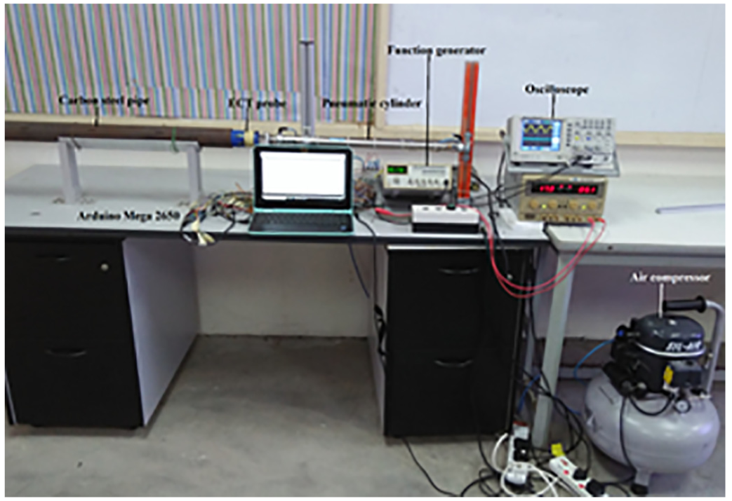
Eddy current testing inspection system.
Figure 6 shows a prototype of the proposed GMR-BC probe. The inducer coil of the probe is constituted of 35 mm height, 31 mm inner diameter, 51 outer diameter single layered BC featuring 10 mm and 500 turns wound with a 1.75 mm diameter copper wire. A commercial IR sensor (TCRT1010) with dimension 7 mm length, 4 mm width, and 2 mm depth was used to measure the change in the distance between the probe and the wall of the pipe. It has a compact construction where the detector and emitting-light source are aligned in the same direction to observe the occurrence of an object by employing reflective IR-beam from the object. The TCRT1010 is the reflective sensor which includes a phototransistor and infrared emitter. A 220 ohms resistor is used in series with the IR LED and 2.2 k ohms resistor is used to ground the signal in the normal condition to solve the problem of bubble high.
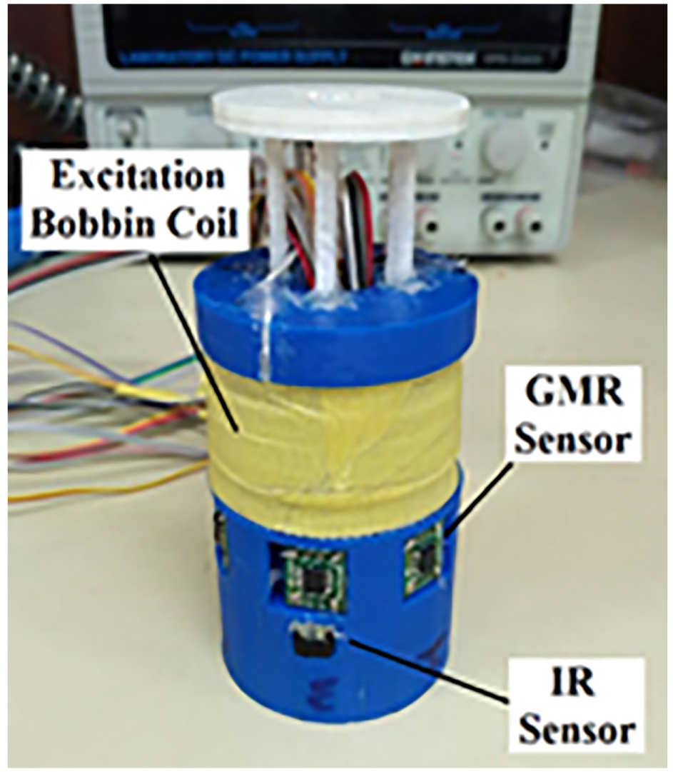
The schematic of GMR-BC probe.
Results and discussion
The experimental trials were performed to evaluate the influence of lift-off on defect measurement in ECT using GMR-BC probe without a compensation technique. In the experiment, the coating thickness shield is utilized to change the distance between a GMR-BC probe and the sample of a pipe. The detected signal was acquired and changed to a voltage signal through the GMR sensor by a data acquisition system. In the experiment, the material of the sample is carbon steel; it is commonly used in oil and gas pipelines. The geometric factors of the sample pipeline are presented in Figure 7. Different artificial crack sizes were processed in the carbon steel pipe through an electrical discharge machining (EDM) technique. There are inner-wall axial and hole cracks with varying depths (1, 2, 3, and 4 mm).
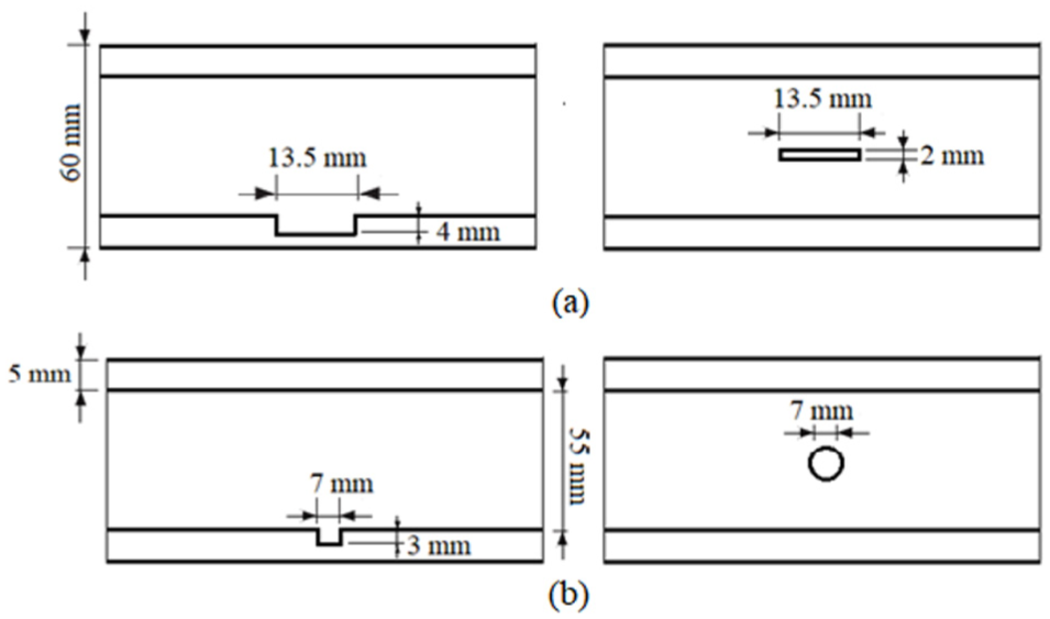
The geometric parameters of the sample with artificial defects: (a) axial defect and (b) hole defect
Calibration of eddy-current sensors
The GMR and IR sensor outputs were calibrated with different depth defects and lift-off respectively and used as linguistic variables for the set of input fuzzy. The experiment was conducted using the current amplitude through the coil. A function generator of 8 VAC was used to achieve the voltage step from the main source to generate the magnetic field and frequency of 30 kHz. For the estimation of subsurface cracks, it is imperative to reduce the excitation frequency to improve field penetration. During the experiments, the lift-off distance remained zero; supplementary experimental runs were done to calibrate the output voltage of the IR sensor with different lift-offs. The input across the two arms of the sensor bridge network was supplied by a direct current (DC) voltage of 5 V. The distance of the lift-off was varied between 1 and 4 mm. An IR sensor was used to measure the lift-off distance between the GMR-BC probe lower face and specimen surface. During measurements, the lift-off was changed to ensure the reading of the lift-off signal. For an accurate verification, the test was done using the coating shield thickness. The measuring tolerance of this system is +/-10% from the actual lift-off. The result of the sensor’s output signal is presented in Table 2.
The result of calibration the GMR/IR sensors.
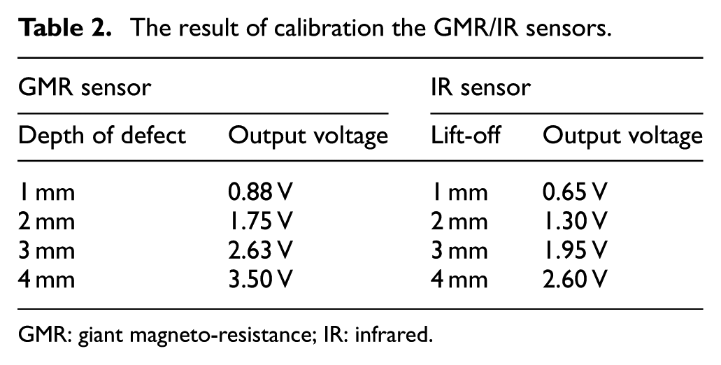
GMR: giant magneto-resistance; IR: infrared.
Analysis of the lift-off effect in the GMR-BC probe
The peak value is mostly utilized for the quantification of the defect geometric characters as previously introduced.4,8,29,30 However, the lift-off resulted in the variation in peak amplitude value of the detection signal, as can be seen in Figures 8 and 9. The same phenomenon has been found when aluminium alloy was used as the material. 21 The lift-off effect directly influences the determination of defect geometric factors based on the experimental comparison.4,8 Therefore, it is very essential to implement a technique to remove the lift-off effect in ECT detection.
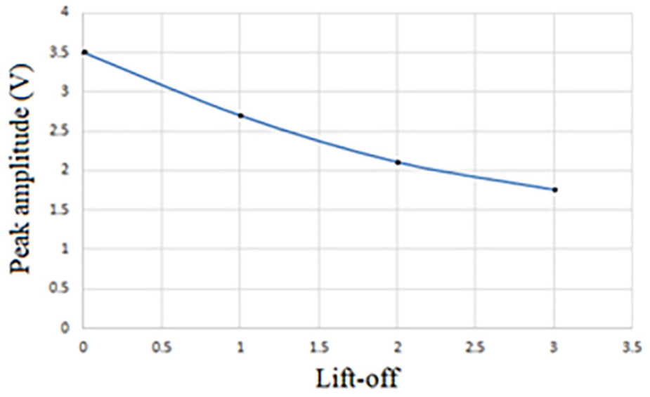
The relationship between the peak amplitude of the GMR signal and lift-off under an axial defect with 4-mm depth.
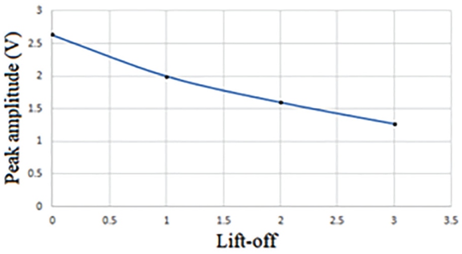
Relationship between the lift-off distance and the peak amplitude of GMR signal for a hole defect with 3-mm depth.
Analysis of the lift-off effect in industrial instrument measurement
The commercial differential probe (EG phase) was used to examine the influence of lift-off in ECT. The calibration block of carbon steel with dimensions of 260 mm (length) × 30 mm (width) × 10 mm (height) was used as shown in Figure 10. Three slots of artificial defects with different depths of 1 mm, 2 mm, and 3 mm were used to get the relationship between the physical dimension of the machined cracks and the response of the ECT. During measurements, the lift-off was changed using the coating shield thickness.
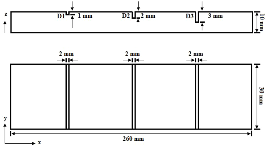
Front and top views of the carbon steel calibration block.
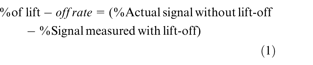
The percentage measurement signal of the differential probe is inversely proportional to the lift-off and is directly proportional to the depth of the defect. Based on this relation, calibrating the measuring plate or pipe without lift-off will show the actual percentage measurement value or reference value. The signal produces a decrease according to the distance between the sample and the probe as can be seen in Table 3. The percentage of lift-off rate can be calculated by using equation (1)8,27
The result by commercial differential probe.
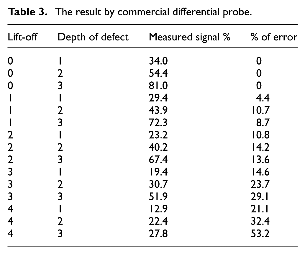
The defect geometric factors can be quantified based on the level of the peak amplitude of the GMR signal on the EC detection. To minimize the effect of lift-off noise, the peak values of the GMR signal with various lift-off have been studied. Moreover, the commercial differential probe was used to evaluate the influence of lift-off in inspecting carbon steel plate under different lift-offs. The output voltage value of ECT was observed to be changing with changes in the depth of a defect and lift-off at the pipe and plate surface. This condition is obvious for the defect and lift-off measuring ≥ 1 mm. This condition also demonstrated that the measurement accuracy of ECT is affected by variation of the lift-off in the range of 1–4 mm and needed to be compensated. For that purpose, the error compensation technique has been postulated using Mamdani fuzzy type to minimize the influence of lift-off by comparing the peak amplitude of a GMR sensor with a peak amplitude of the IR sensor. The relationships between the set of input and output are defined to an accurate depth of defect reading.
Comparison of lift-off signal error using fuzzy logic
The experimental trials were performed to reduce the influence of lift-off on defect measurement in ECT by using a GMR-BC probe with an error compensation technique. The experiment was conducted using a current amplitude supplied by a function generator of 8 VAC. The voltage was acquired through a voltage step down from the main source and used to generate the magnetic field and frequency of 30 kHz. For the estimation of subsurface cracks, it is important to excite the low frequency to improve field penetration. During experiments, the lift-off was varied in the range of 1–3 mm. Lift-off mostly occurs during measurement; lift-off compensation defines the actual value of a crack. Figure 11 illustrates the FIS for error compensation signal output without lift-off for the peak amplitude of the GMR output signal for an axial defect with 4-mm depth. The blue line graph is considered as a reference value of the peak amplitude of the GMR output signal, and the red line graph is a fuzzy output after the consideration of lift-off for error compensation. The value of the peak amplitude of the GMR output signal was 3.45 V while the fuzzy output value was 3.5 V.
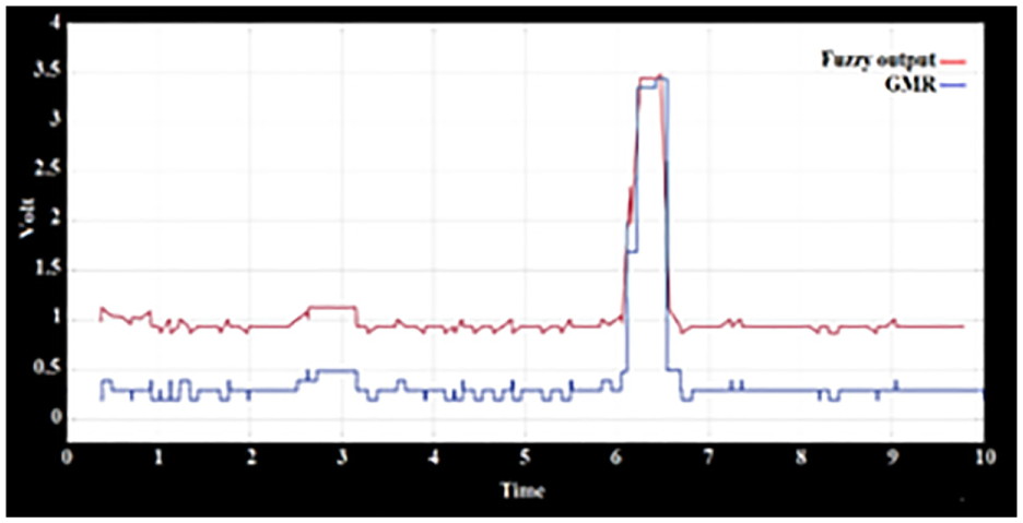
Fuzzy logic for error compensation signal output without lift-off.
The FIS for error compensation signal output under different lift-offs for an axial defect with 4 mm depth is shown in Figure 12. The peak amplitude of the GMR output signal decreased slightly from the actual value of defect with increasing lift-off. Figure 12 illustrates the effect of fuzzy logic on the lift-off error compensation signal output with 1, 2, and 3 mm lift-offs. In Figure 12(b), the peak amplitude of GMR output signal was 2.70 V, corresponding to the maximum measuring depth defect of 3 mm, while the value of fuzzy output was 3.35 V. The value show approximately 4-mm depth defect. Figure 12 (a), (b), and (c) clearly show that the compensated peak amplitude increased slightly with an initial increase in the lift-off. The values of the fuzzy outputs were 3.50, 3.35, and 3 V, showing a depth defect of approximately 4 mm. However, in the case of 3 mm lift-off as seen in Figure 12(d), the value of the fuzzy output improved the measurement of the reference signals from 1 to 3 mm. Figure 13 shows the fuzzy logic for error compensation signal output for the peak amplitude of GMR signal for a hole defect of 3 mm depth and 0, 1, 2, and 3 mm lift-offs.
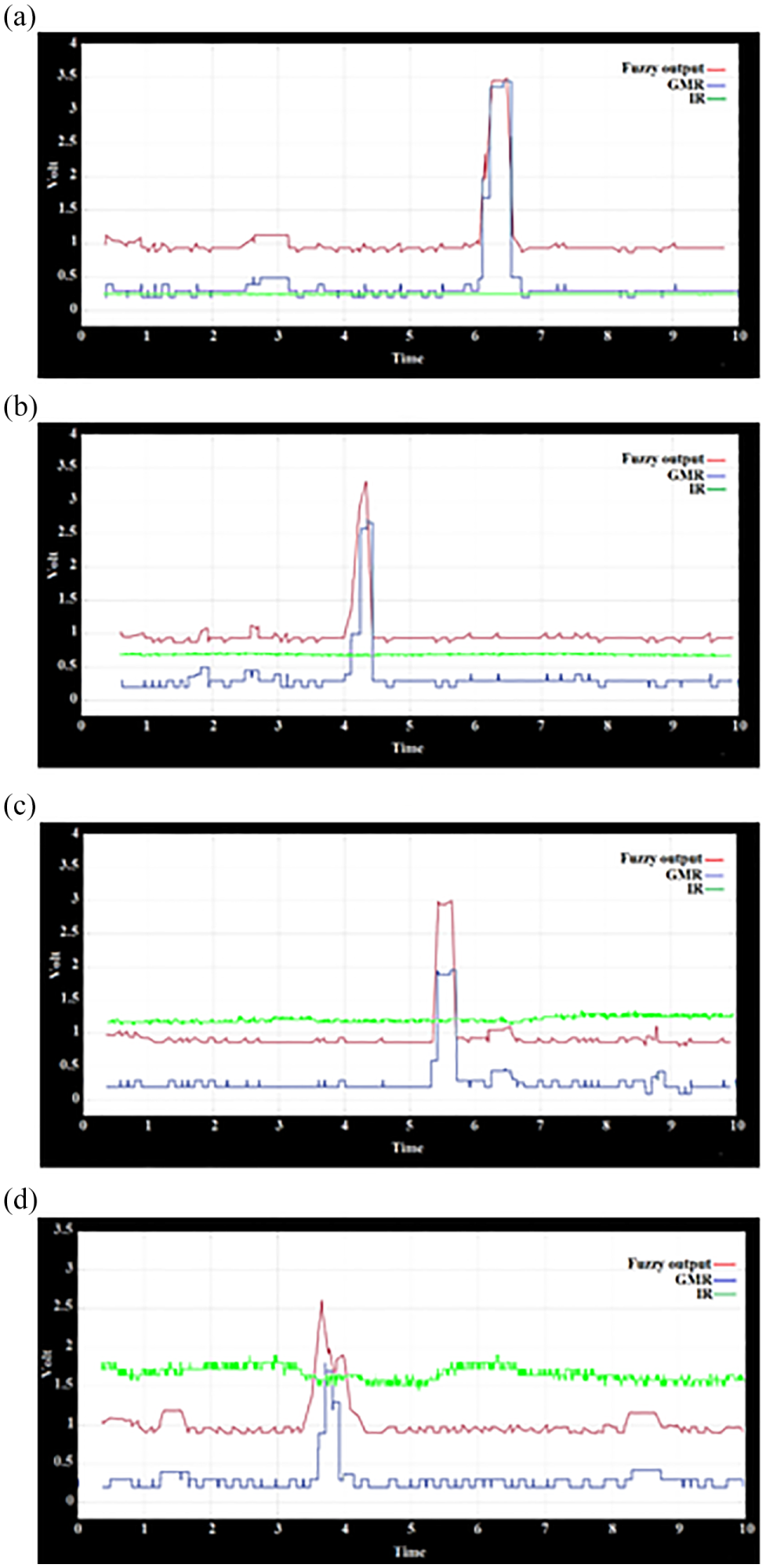
Fuzzy logic for error compensation signal output for axial defect with 4-mm depth and under lift-offs of (a) 0, (b) 1, (c) 2, and (d) 3 mm condition.
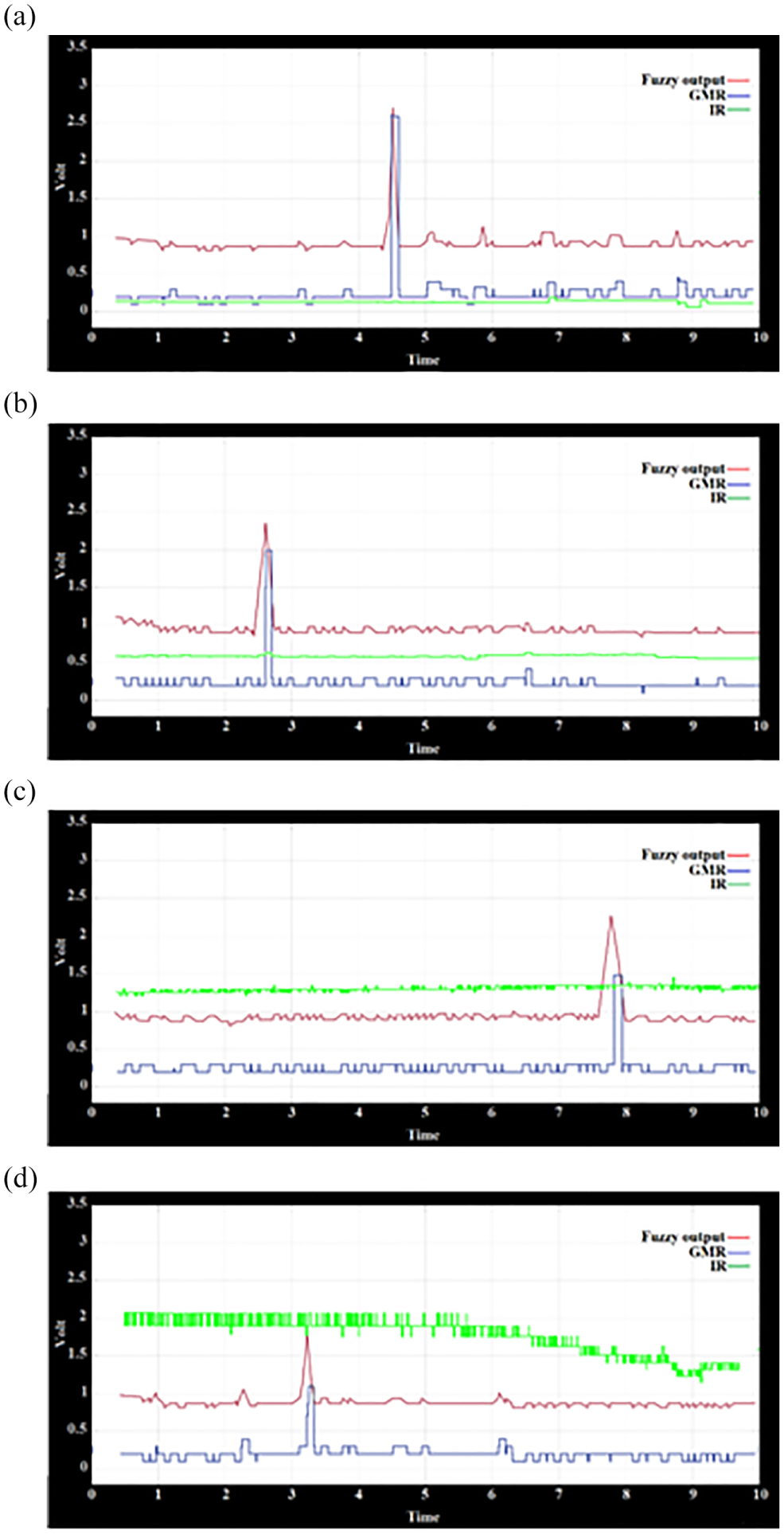
Fuzzy logic for error compensation signal output for hole defect of 3-qmm depth and under lift-offs of (a) 0, (b) 1, (c) 2, and (d) 3 mm condition.
The compensated peak amplitude increases slightly with initial increased of lift-off as can be seen in Figure 13(a)–(c). The value of fuzzy output is equal to 2.63, 2.40, and 2.25 V, which shows approximately 3-mm depth defect. However, in the case of 3 mm lift-off as seen in Figure 13 (d), the value of fuzzy output improves the measuring of the reference signals from 1 to 2 mm. The analysis on the defect signal for an axial defect with 4-mm depth defect and hole defect with 3-mm depth defect shows that the proposed error compensation technique is accurate in the measurement when the lift-off is equal to or less than 3 mm.
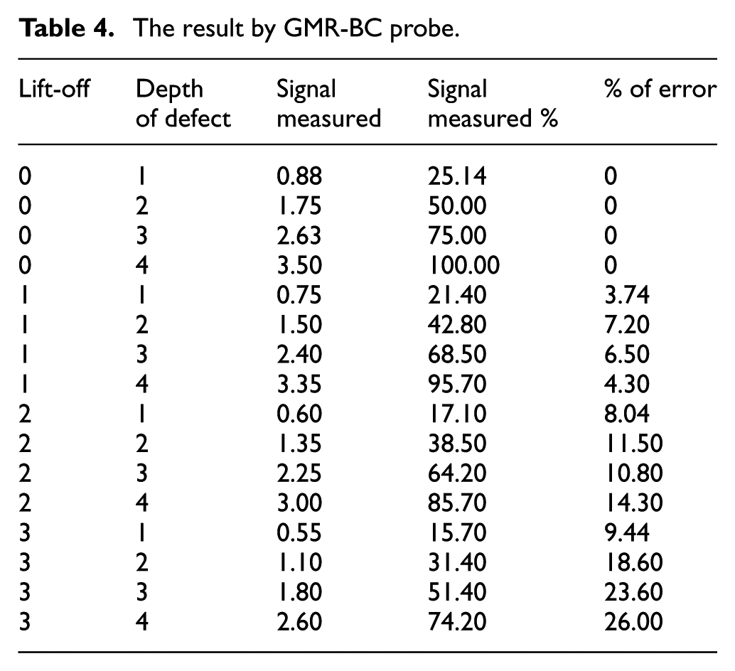
In Figure 14, the fuzzy output decreased slightly with an initial increase in the lift-off, but the fuzzy output signal and the GMR output signal as determined for larger lift-offs were still smaller than that for zero lift-offs as listed in Table 4. The percentage of error of the measured signal using the compensation technique was within 26% when the lift-off was 3 mm.
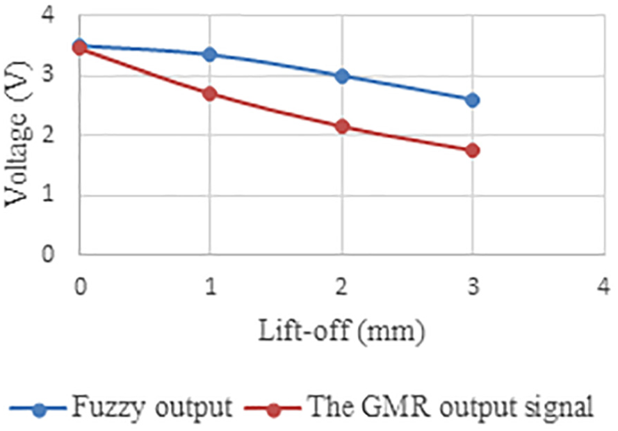
Comparisons of GMR output signal (uncompensated) and fuzzy output compensated for depth defect 4 mm at a range of lift-offs.
The result by GMR-BC probe.
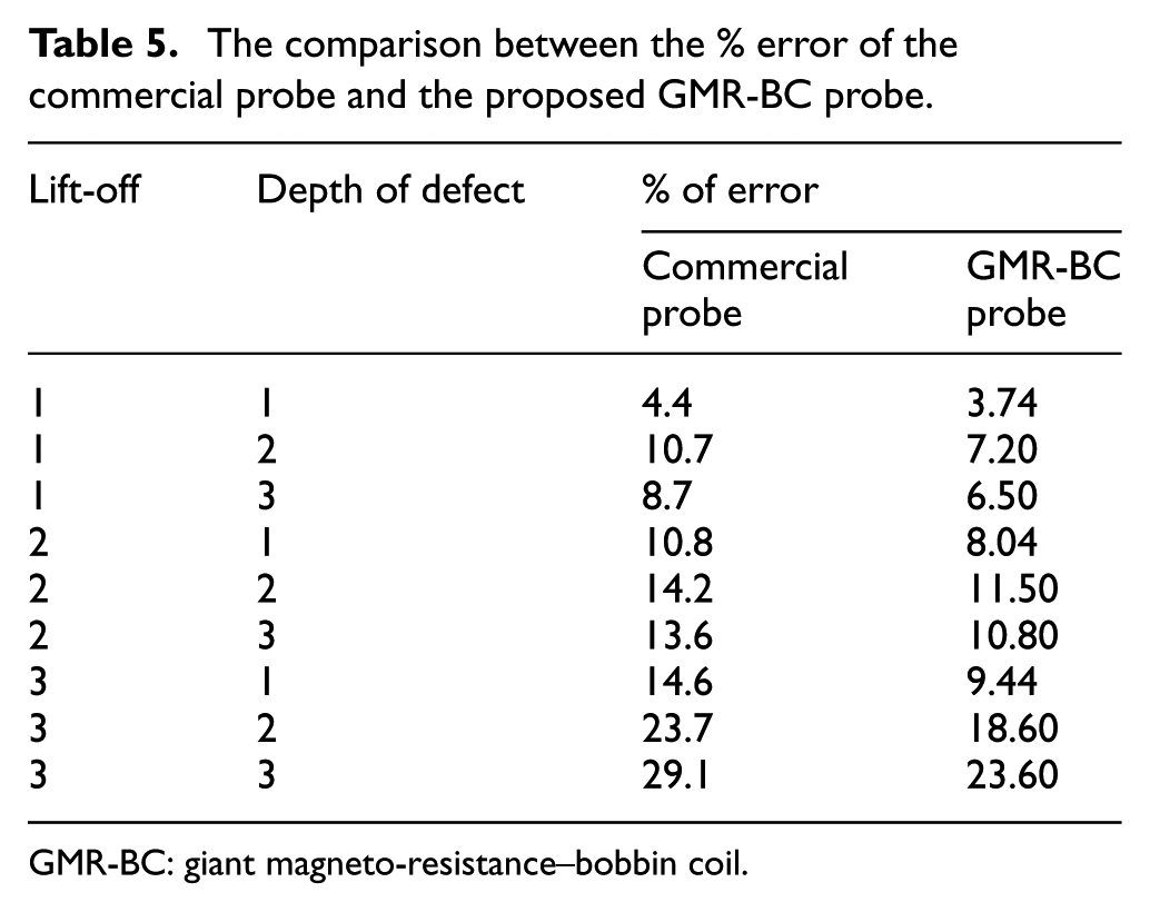
To verify this method, comparison was done between the percentage error of the compensation technique results for GMR-BC probe with the percentage error of the commercial differential probe results as shown in Table 5 for varying depth defect and lift-offs. Table 5 listed the percentage error when the commercial differential probe was utilized to evaluate the depth defect under different lift-off. The depth defect evaluates the relationship between the depth defect and the peak value of the detection signal. As can be seen in Table 5, the percentage of error is less than 11% for 1 mm of lift-off. Moreover, the increase in lift-off beyond 1 mm increased the effect of lift-off which covers the actual signal of depth defect. The maximal relative measurement error was 30%. Thus, the lift-off noise posed a significant effect on the measured results using the conventional method. To relate its effectiveness for the reduction of the effect of lift-off, the error compensation technique using a Mamdani fuzzy method was added to perform the approach proposed to reduce this effect. The results obtained are presented in Table 5.
The comparison between the % error of the commercial probe and the proposed GMR-BC probe.
GMR-BC: giant magneto-resistance–bobbin coil.
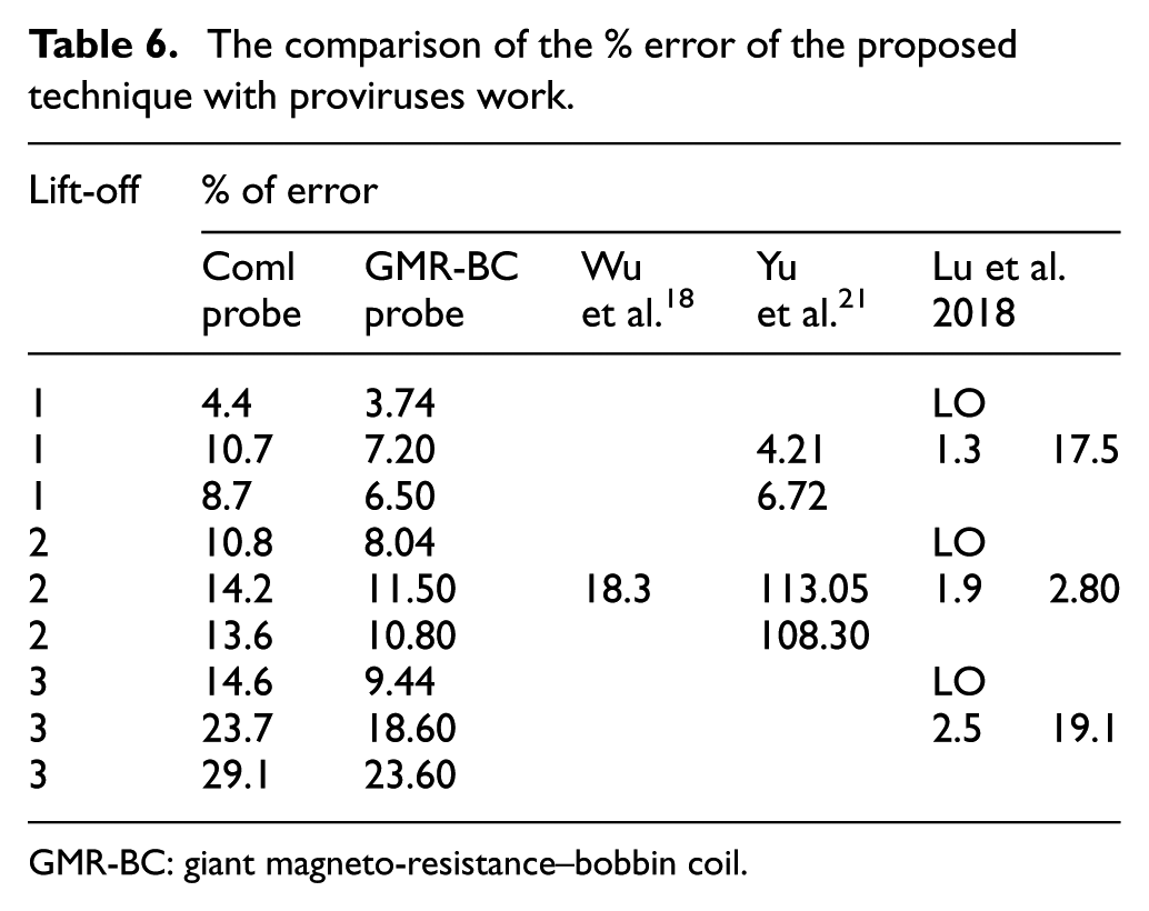
Table 6 shows the results obtained for the lift-off measurements at specific defect depth. In addition, the percentage of error generated from the proposed technique is less than 7.2%, which is significantly lesser than the percentage of error generated through the traditional commercial differential probe. The results reflected that the effect of lift-off on eddy current detection signal has been reduced effectively. Moreover, Yu et al. utilized a Hall sensor to pick up the detection signal for the evaluation of the depth defect under lift-off. When the traditional method was used with a lift-off of 1.0 mm, the relative measurement error was 4.21% and 6.72% for 2 and 3 mm depth defects, respectively. Nevertheless, as the lift-off is beyond 1.0 mm, the maximal relative measurement error was 123.97%. Thus, they developed a new approach to minimize the influence of lift-off by using the slope of the linear curve of the peak value of the difference signal and the lift-off. The percentage of error acquired by this approach is less than 6% under fixed for all lift-offs for specific defect depth. 21 However, it is limited to the lift-off range from 0 to 2 mm and can efficiently minimize the lift-off in non-destructive testing for non-ferrous materials. In another hand, the detection signal variance of the present technique is within a small error of 7.2% which is higher than Yu’s approach, but the range of lift-off is extended from 0 to 4 mm. Mingyang et al. discovered conductivity lift-off invariance phenomenon for permeability measurement immune to lift-off variations. The experimental results showed that the permeability measurement can be evaluated in accuracy with an error of 2.86% without the effect of its conductivity under a lift-off of 1.9 mm. However, the percentage of error increased extremely on the neighbourhood of 1.9 mm where the percentage of error at a lift-off of 1.3 mm reached 17.50%. 31 The error compensation technique using a Mamdani fuzzy method generally improved the accuracy in depth defect measurement and the GMR-BC probe had a simpler structure.
The comparison of the % error of the proposed technique with proviruses work.
GMR-BC: giant magneto-resistance–bobbin coil.
Conclusion
The effect of lift-off can cover useful data in eddy current detection. Moreover, it is hard to circumvent detection. To minimize the influence of lift-off in eddy current detection, this study analysed experimentally the effect of lift-off based on the experimental results which showed the specific exponential relationship as the defect depth remains constant for all lift-offs. The error compensation technique was proposed using a Mamdani-type FIS. In this technique, the defect depth is distinguished through the relationship between the depth defect and lift-off. The input and output MFs were chosen based on the simplicity of the coding algorithm for hardware-based real-time implementation. Rules were generated depending on expert knowledge. A comparison of the proposed technique and the conventional method was done; the comparison illustrated that the postulated technique can significantly minimize the effect of lift-off in ECT within 7.20% of error due to 1 mm lift-off.
Footnotes
Declaration of conflicting interests
The author(s) declared no potential conflicts of interest with respect to the research, authorship, and/or publication of this article.
Funding
The authors are grateful to Universiti Malaysia Pahang and Huaiyin Institute of technology for the financial support through grant No. RDU170379 and JSA2018022.