
Abstract
Eddy current testing plays an important role in numerous industries, particularly in material coating, nuclear and oil and gas. However, the eddy current testing technique still needs to focus on the details of probe structure and its application. This paper presents an overview of eddy current testing technique and the probe structure design factors that affect the accuracy of crack detection. The first part focuses on the development of different types of eddy current testing probes and their advantages and disadvantages. A review of previous studies that examined testing samples, eddy current testing probe structures and a review of factors contributing to eddy current signals is also presented. The second part mainly comprised an in-depth discussion of the lift-off effect with particular consideration of ensuring that defects are correctly measured, and the eddy current testing probes are optimized. Finally, a comprehensive review of previous studies on the application of intelligent eddy current testing crack detection in non destructive eddy current testing is presented.
Introduction
Pipelines are regarded as a preferable way of transporting oil, refined oil products or natural gas in large quantities over land. The network of pipes has advantages over other means of transportation (such as train/truck) because of its high cost.1,2 Thus, it is essential to continuously check the conditions of the pipeline on a regular basis.
The eddy current testing (ECT) method has long been utilized for nondestructive testing (NDT) 3 and widely applied to inspect conductive material structure in order to identify their structural integrity. Betta et al. 4 suggested that coils be used to detect the magnetic field (MF) as the primary indicator of a crack in the pipeline. However, this method is limited due to poor sensitivity at low frequency for the inspection of the subsurface defect, and thickness of materials demands sensitivity at low frequency. To overcome the poor-sensitivity limitation of the traditional eddy current probe, NDT technology has the advantage of employing magnetometer (MR) sensors to obtain maximum information from the component being tested. 5
Many types of research have introduced many structures of ECT for the purpose of material inspection. Lee et al. 6 proposed that the bobbin coil is used to induce the eddy current in small piping, and the MF can be picked up by utilizing a Hall sensor array. This technique allows the distribution of the distorted electromagnetic (EM) field around outside diameter of the stress corrosion cracking so it can be imaged without the need for a rotating apparatus. In another study, Postolache et al. 7 proposed two rectangular planar excitation coils and an array of five AA002 giant magneto resistive (GMR) sensors for defect detection of an aluminum plate. They found that the optimization of the ECT probe had enhanced the ability of inspection with rapid scanning time.
Ye et al. 8 used a pair of orthogonal (axial and circumferential) coils to generate an eddy current in steam generator tube wall and a GMR array to detect the induced MF. The probe showed superior inspection accuracy and sensitivity to defects of the axial and circumferential directions. Zeng et al. 9 suggested a multi-line as an excitation coil, while a GMR sensor could be placed on the line of symmetry to detect any changes in the MF. The simulation result shows improvement in the detection sensitivity for multilayer subsurface flaws.
Rifai et al. 10 also described the application of GMR sensors in ECT. Also discussed in detail were the limitation of utilizing the coil as a sensor and compensation techniques that have been used in the ECT. In another study, Ali et al. 11 discussed in detail the method of the ECT and the parameters that impacted the signal fundamental in relation to the hardware and software. García-Martín et al. 12 delibertated an overview of the primary variables and the principles of ECT sensors.
Therefore, the structure of the ECT probe should be identified to provide and evaluate the tested materials without destroying them. 13 This paper will review the eddy current probe structure and error compensation of the eddy current probes to obtain the ideal measuring depth of defect on carbon steel pipeline. The lift-off effect will be discussed in detail to ensure that the measuring defect is right. This study will also introduce different conventional and intelligently lift-off compensations.
The principle of ECT
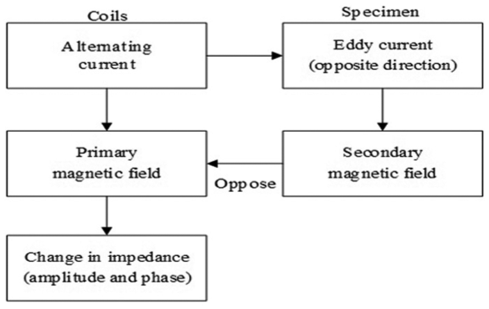
The diagram illustrating the operation principle of the ECT is shown in Figure 1. According to Faraday’s law, the driving coil is excited to produce a MF, known as eddy currents.14–16 The emf induced in the receiving coils are generated by the eddy currents.
Principle for the eddy current testing operation.
Four steps can demonstrate the MF connection between the primary and secondary coils:
Alternating current through the coil produced by the principal MF.
Alternating primary MF produces the EC in the conductive sample.
EC produces a secondary MF in an opposing direction.
Flaws in the sample perturb the EC and decrease the secondary MF, which results in the variation of impedance changes of the coil.
The advantages of ECT include the fact that they are economical and environmentally friendly as a non-contact method with high detectability, inspection speeds and offers good discrimination. On the other hand, the main disadvantages are it is sensitive to defects near the surface and is only applicable to conductive materials.12,17
Eddy current probe
Various configurations are presented for the excitation source and detection sensor. However, in many in-service applications, the inductive coils are utilized both as a field source and field sensors. As a result, the eddy current probes are commonly classified according to their configuration and mode of operation. The probe configuration is closely related to the way the coil or coils’ connection covers the testing area of interest. The probe operation mode is commonly classified into reflection, differential, absolute and hybrid modes, whereas some of the standard configurations include the outside diameter probes, inside diameter (bobbin) probes, bolt hole probes and surface probes. 18
An inductive probe can include one or more coils. In conventional eddy current probes, these coils typically comprise lengths of wire wound in a helical manner like a solenoid. The winding will commonly have more than one layer to increase the value of inductance. As mentioned above, there are many ways in which these coils can be constructed based on the specified application. Conventional ECTs are transmit–receive probes, multi-pancake and/or rotating pancake probes and bobbin probes. Each method has its respective strengths and weaknesses in consideration of their characteristics such as the test speed, flaw detection sensitivity and probe structure complexity. 19
Bobbin probes
Figure 2 shows the two types of the bobbin probes which are called the differential and absolute bobbin probes. Differential bobbin probe has two coils positioned at 180° out of phase. The probe has excellent sensitivity to detect abrupt anomalies and small defects such and relatively unaffected by lift-off, pitting corrosion, fretting wear and probe wobble. However, the probe is not sensitive to metallurgical and gradual changes.20,21
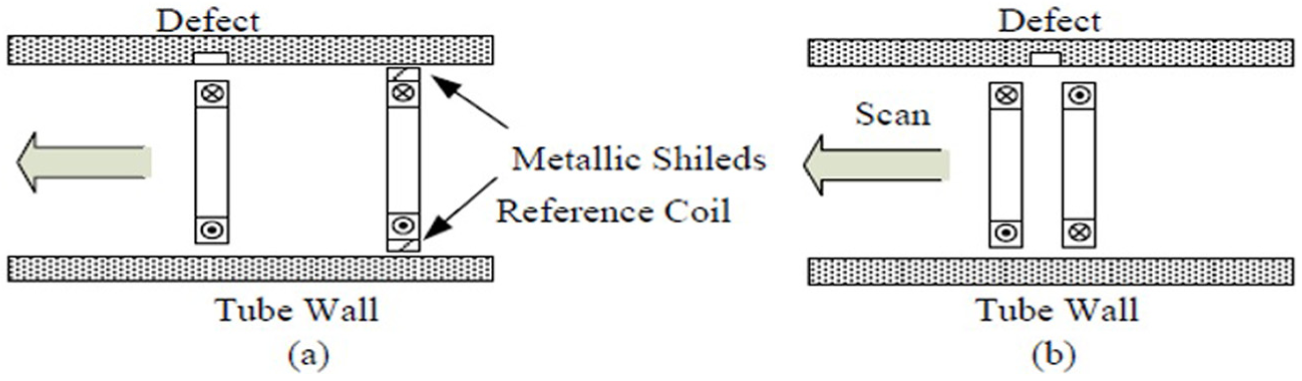
Tube inspection probes: (a) absolute and (b) differential.
Absolute bobbin consists of a single bobbin coil and a second identical reference coil. The second identical reference coil is used for EM shielding of the inspected tubing and electronic balancing. The probe has excellent sensitivity to detect axial cracks and is highly sensitive to material property variations and gradually varying wall thinning. 6 The main disadvantage of the absolute coil is that the defect is typically superimposed over a lift-off as the large signal.
Rotating probes
The rotating eddy current probes are used for high-resolution imaging of the steam generator tubes as shown in Figure 3.8,22 The rotating probe is sensitive to defects of all orientations and has a high resolution and improved sensitivity to characterize and size defects. However, the mechanical rotation of the coils causes serious wear leading to frequent probe failure and affect the inspection time, and subsequently, the cost will increase significantly. 23
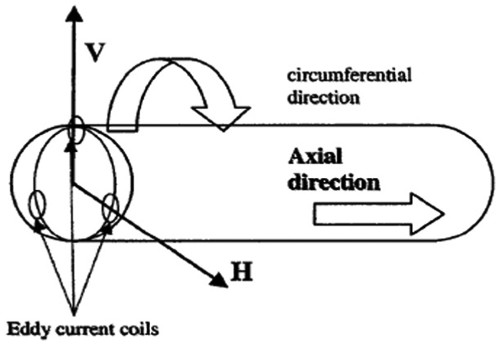
Rotating probe.
Array probe
The array probe types include the smart, probe X-probe, C-probes and intelligent probe. The array probe works as a transceiver probe and can cover the direction of 360°. The transmitting coils are actively driven by the AC source with a different range of frequencies. The receiving coils generate an induced voltage equal to the change of magnetic flux through the coil. The array probe response for different orientation defects has a higher signal-to-noise ratio (SNR) and is 10 times faster than the rotating probe. Another disadvantage is that the hand array probe is very costly because of its complicated excitation and data acquisition parts24,25 as shown in Figure 4.
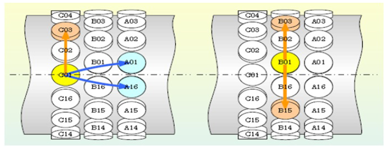
Array probe.
Rotating field probe with bobbin coil
Figure 5 shows the excitation part which consists of three coils with identical 120 axes degrees apart and balanced alternating currents with adjustable frequency, phase and amplitude. The rotating MF is generated without mechanical rotating support.21,26
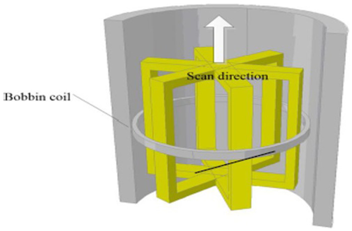
3D model of rotating field probe with bobbin coil.
Comparison of eddy current probes
The advantages and disadvantages of eddy current probes for the NDT as described in Table 1. 30
ECT probes for tube or pipe assessment inspection.
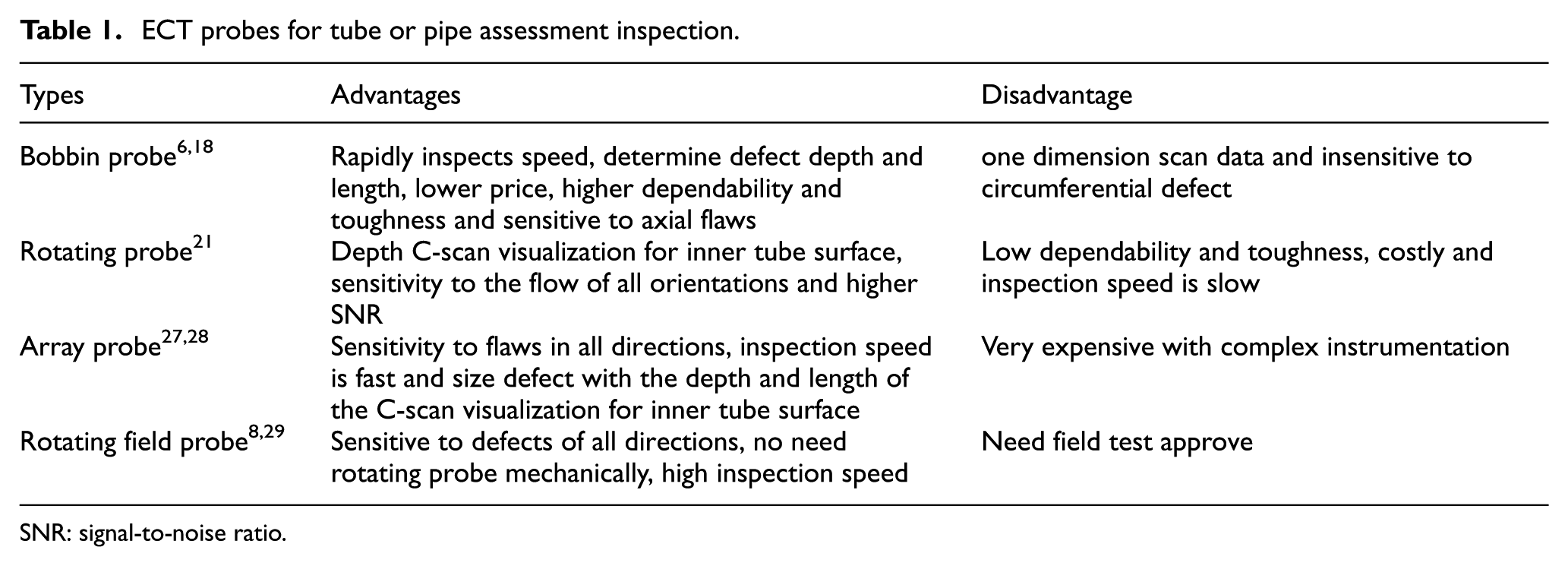
SNR: signal-to-noise ratio.
EM NDT techniques
The EM methods of NDT comprise a full spectrum of techniques ranging from static (DC) methods to high-frequency (10 THz) methods. The next section presents the most comprehensive inspection technique that used in the EM NDT. 31
Pulsed eddy current
Pulsed excitation produces transient signals with a wide range of frequency components. Hence, it contains more information compared to a single-frequency excitation.32,33 The pulsed eddy current (PEC) signals have common features in the transient characteristics such as the peak amplitude, time-to-peak amplitude and time-to-zero crossing. The peak amplitude will determine the defect size. The defect depth or material thickness will be identified by the peak amplitude.34–36 The earliest study of PEC for crack detection in layered structures with installed fasteners was conducted by Harrison.37,38 Giguere et al. 39 also studied the detection of cracks beneath rivet heads using the transient EC techniques. Figure 6 shows some experimental results of PEC to test multilayer sample. 33
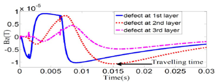
PEC to test multilayer sample. 33
ECT with MF measurement method
The most recent research introduced the GMR sensor. It is widely used in many applications because the sensitivity of these sensors is independent of the MF, it has a high bandwidth, only requires a low power supply, the dimensions of GMR are small and the output signal is high compared to the other MR sensors. Therefore, the GMR-based EC testing exhibits significant advantages in detecting complex geometry such as a layered component inspection. 40 The directional property of the GMR sensor had been used to locate edge cracks in aluminum specimen.40,41 A needle-type GMR imaging technique named the SV-GMR system was designed for the inspection of a bare polychlorinated biphenyl structure to measure the magnetic fluid density in a living body.10,42
High-resolution GMR elements are fabricated in a small package of sensors arrays. An inspiring application of this array probe was found in the evaluation of metal medical implants for invisible cracks. 43 A linear array of 20 GMR elements was packaged to image a hole defect in a steel plate using 1 Hz excitation. Designs of GMR array probes in identical elements had been studied to detect subsurface cracks. 44 High-density GMR arrays were especially promising for rapid scanning of a large area as well as high-resolution imaging.7,45 Another type of GMR array sensors that use two-directional elements was investigated in the EC testing to detect surface cracks of unknown orientation. They measure both X-component and Y-component of the MF at the same point. 5 A fast Fourier transformation to enhance the ECT probe based on the GMR array sensors for pipe inspection was utilized by Du et al. 46
The transient excitation of the coil probes with two MR sensors or two Hall sensors in differential mode have been studied by Lebrun et al.47,48 and used for characterizing crack parameters. Kim et al. 49 introduced a method for the assessment of aircraft structures. The system produced pulse excitation that energized a planar multi-line coil. The GMR field sensor was used to detect the transient field. Tai et al. 50 studied similar transient features for an inversion scheme to qualify the conductivity and thickness of the samples. Table 2 shows the difference between the eddy current methods which rely on the sensor element that utilities alternative current signal in ECT.
Overviews of the utilities AC signal in eddy current testing with different probe designs
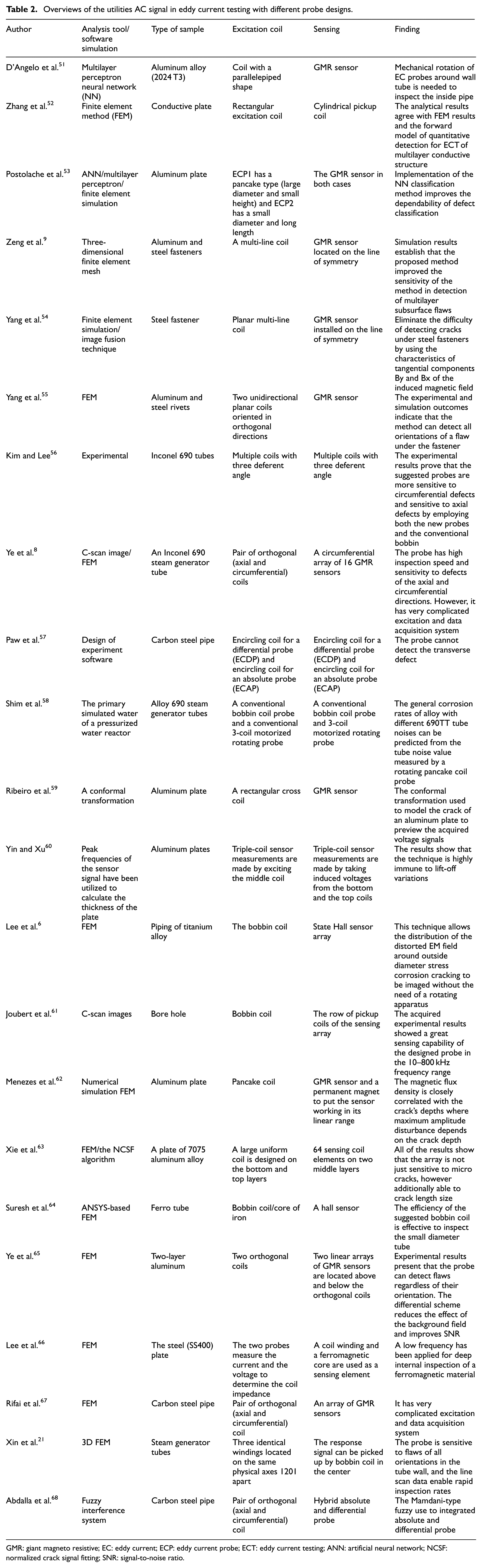
GMR: giant magneto resistive; EC: eddy current; ECP: eddy current probe; ECT: eddy current testing; ANN: artificial neural network; NCSF: normalized crack signal fitting; SNR: signal-to-noise ratio.
Multi-frequency techniques
NDT widely uses multi-frequency techniques (MFTs). The MFT expanded the capabilities of using single-frequency testing which allows simultaneous tests.
The multi-frequency process uses a composite signal and subtracts the undesirable signal. 12 The main undesirable signal caused by changes in the temperature variation, material geometrical and probe lift-off. 69 MFTs are usually accomplished by combining the results obtained at different frequencies in the spatial domain. Liu et al. 69 presented integrate two- (multi) frequency injection with dimensional spatial domain named as a pyramid fusion method. The SNR improved due to reduction in noise sources which demonstrated the potential of signal enhancement via fusion method or raster scanning. 70 A two-dimensional (2D) surface produced changes over of the impedance or impedance by raster scanning images. 12 Image processing techniques can be applied to detect cracks using ECT. Bartels and Fisher 71 proposed a multi-frequency eddy current image processing technique for the non destructive materials evaluation. SNR improvement up to 1100% over traditional two-frequency techniques a sequence of complex valued images generated from 2D ECT to maximize the SNR. The linear combination of the images by Bartels and Fisher 71
where Nf is the number of test frequencies and fi are extracted from the 2D images. Results on experimental data demonstrate.
Factors contributing to eddy current signals
The signal from an eddy current probe includes a collection of responses from defects, sample geometry and probe lift-off.72,73 Therefore, it may be difficult to separate a single influence. Adequate assessment of flaws or any other surface properties is likely when other factors are understood. 7 The primary factors influencing the response of an eddy current probe are explained in this section.
Frequency
Eddy current response is strongly affected by the frequency chosen for the investigation. This factor should be appropriately selected by the operator, based on the crack detection sample such as lower frequencies for bulk characterization and higher frequencies for surface characterization.
Many authors such as Ditchburn et al. 74 and Thollon et al. 75 utilize this range, and they suggested the range of 100 Hz–10 MHz as standard inspection frequencies in ECT. 19 However, a few authors such as Owston 76 characterized high frequency at 25 MHz for thin metallic coatings and detecting surface defects. In the inspection of ferromagnetic materials, low-frequency tests are applied to penetrate into the test specimen and compensate for their high permeability. Ramos et al. 77 have studied the detection of subsurface flaws relating to the characterization of depth profiles of the subsurface defects in aluminum plates. 78 However, the high frequency applied for the inspection of small discontinuities occured in the near-surface.79,80Table 3 summarizes the impact of different frequency values on the depth of penetration of several materials. 81
Typical depths of penetration.
Conductivity of test material
Electrical conductivity and the magnetic permeability of the test objects of the material depend on the microstructure, for example, grain structure, the presence of a second phase, work hardening and heat treatment. Greater conductivity of a material such as copper and aluminum will lead to greater flow of the eddy currents and hence the probe coil resistance.
In great conductive materials, defects or cracks produce a high signal as an impedance plane, as illustrated in Figure 8. Furthermore, the phase lag between the lift-off line and the defect is ϕ1 > ϕ2, 82 which is significant, as indicated in Figure 7.
Lift-off curves and crack displacement at impedance plane. 82
However, the penetration depth of highly conductive materials at a fixed frequency is lower than in lower conductive materials such as stainless steel and steel. The conductivity of the different materials can be measured using the International Annealed Copper Standard (IACS). Table 4 summarizes the conductivity of common elements. 83
Conductivity and resistivity of conductive materials.
Magnetic permeability
ECT signals are significantly affected by ferromagnetic materials due to the increase in flux produced by the significant relative permeability of certain materials such as stainless steel or carbon steel. 84 The permeability of material changes the coupling of the coil with the conductive specimen and subsequently affects the reactance of the coil. Permeability has a significant effect on the ECT compared to conductivity, where the crack detection has no potential when permeability changes randomly.85,86
Lift-off
ECT is strongly affected by the amount of lift-off which can be defined as the separation distance between the excitation coil surface and the conducting material surface. This distance changes the mutual inductance of the circuits as the lift-off increases; the amplitude of the eddy current induces emf as the secondary coil decreases, which can result in the misinterpretation of the signals as flaws. At a significant lift-off, no detectable emf will be induced in the secondary coil due to the sample chosen.81,87,88 This effect is particularly prominent when using sinusoidal excitations, which lose sensitivity beyond 5 mm. 89 Although it is not required to have a zero lift-off, it is imperative to try and maintain a consistent lift-off, since the variation in coupling between probe and test piece will significantly affect the received signal. Table 5 lists previous studies that have considered the lift-off issue.
Review of lift-off compensation techniques
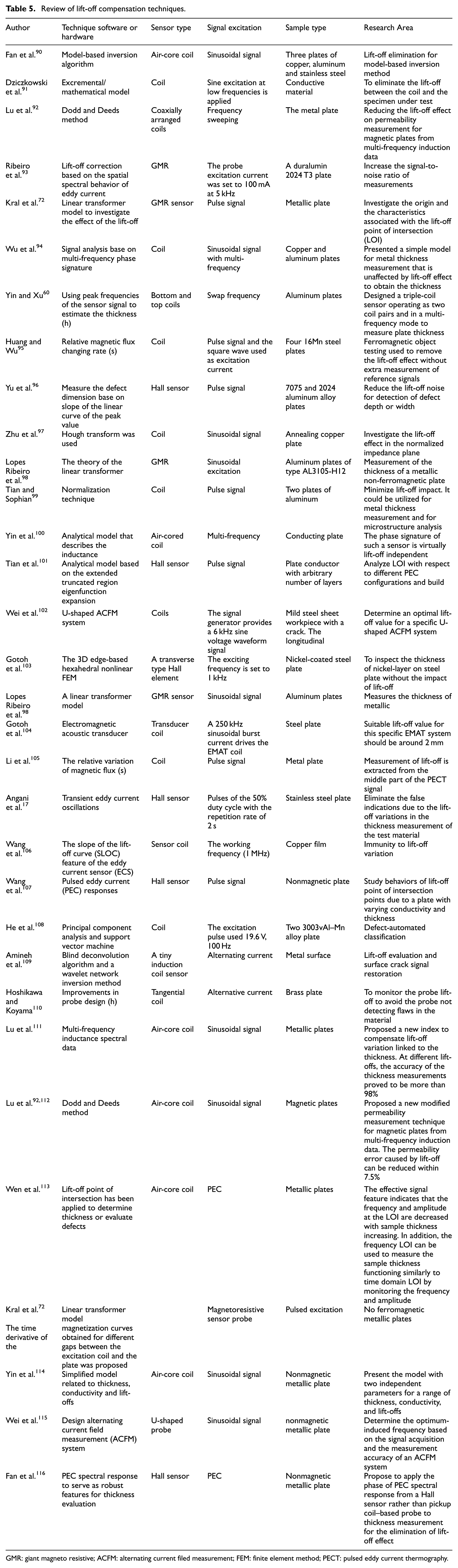
GMR: giant magneto resistive; ACFM: alternating current filed measurement; FEM: finite element method; PECT: pulsed eddy current thermography.
Figure 8 illustrates the offset position of the tube inside the bobbin coils. Lift-off is explained using a coil whose axis is normal to the test piece. However, lift-off also occur when the test is conducted using encircling or bobbin probes. The vibration of the rod or the tube inside the probe generates noise which presents difficulties when inspections are conducted. 117
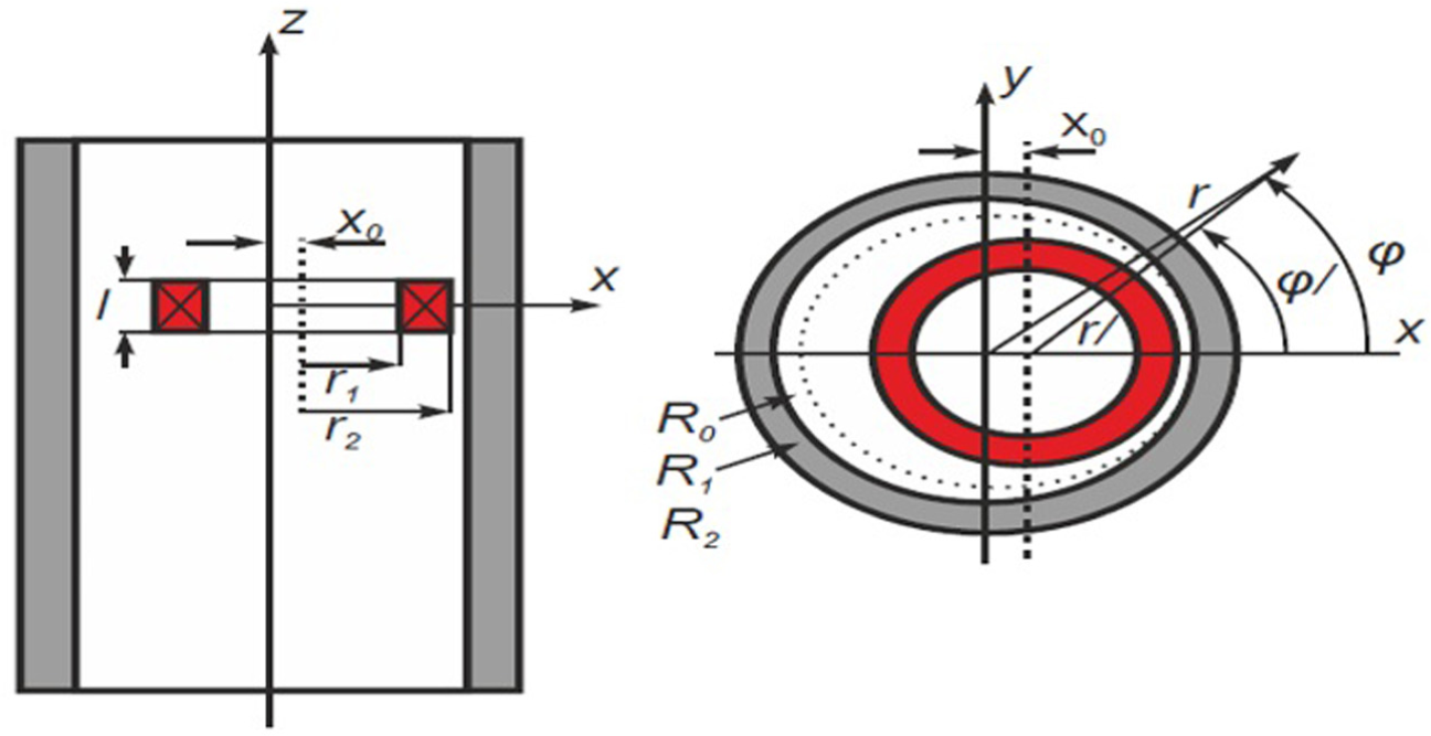
Wobble simulation: a bobbin coil in an offset position to a tube. 87
There are methods for lift-off compensation when the eddy currents are used in order to detect cracks, and lift-off becomes an undesired variable. For instance, Yin et al. 100 researched dual excitation frequencies and coil design to minimize the lift-off effect. Research about processing the data was also conducted to minimize the lift-off effect. Lopez et al. 118 proposed the use of wavelets to remove the eddy current probe wobble noise from the steam generator’s tubes. Reduction in the lift-off effect was also attempted by optimizing the coil design and sensor array. 119
Tian et al. 101 had researched the reduction of lift-off effects via normalization techniques. The technique can be applied to the measurement of metal thickness beneath the non-conductive coatings and to the measurement of microstructure and strain/stress, where the output is highly sensitive to the lift-off effect. Table 5 illustrates previous studies that considered the lift-off issue.
Optimization of ECT probes design
According to the state of the art, the probability of detection techniques of eddy current techniques can be improved by the optimizing the probe design. In recent years, several studies have focused on optimization of the ECT probe design for defect detection. Rocha et al. 120 proposed an ECT probe design based on velocity-induced eddy currents to detect surface defects. Commercial simulation software was used for the optimization and design of the probe. Their experimental results confirmed that the proposed probe design was able to detect defects in the conductive materials where motion is involved. 120 A biorthogonal rectangular probe was developed by Zhang et al. 52 Simulation results showed the new biorthogonal rectangular probe has a lesser effect on the lift-off with higher sensitivity detection. Meanwhile, Cardoso et al. 121 optimized the sensor configuration in the eddy current probe design. A finite element modeling simulation was used to measure the accuracy detection of the probe design. Comparison of experimental and simulation date proved the accuracy of the proposed probe. Research by Rosado et al. 122 reported the influence of the geometrical parameters of an eddy currents planar probe in ECT. The findings showed that modifications of the studied parameters could substantially improve the probe performance. In a different study, Ghafari et al. 123 proposed a methodology for determining the optimal sensor parameters for ECT probe design. Simulation results showed the proposed sensor geometry improved the probe sensitivity to depth changes in a crack.
Chen and Miya 124 proposed ECT probes based on simplified detectability analysis method and a ring current model. The optimal probe designs are developed in view of the combinations of these excitation and pickup coils by comparing their detectabilities evaluated with the simplified analysis method. Aldrin et al. 125 presented a comprehensive approach to perform model-based inversion of crack characteristics using bolt hole eddy current techniques. Signal processing algorithms were developed for wide range of crack sizes and shapes, including mid-bore, corner and through thickness crack types. Inversion results for select mid-bore, through and corner crack specimens are presented, where sizing performance was found to be satisfactory in general but also depend on the size and location of the flaw. Table 6 summarizes previous studies on the optimization of the ECT probe design.
Summary previous studies on optimization of ECT probe design.
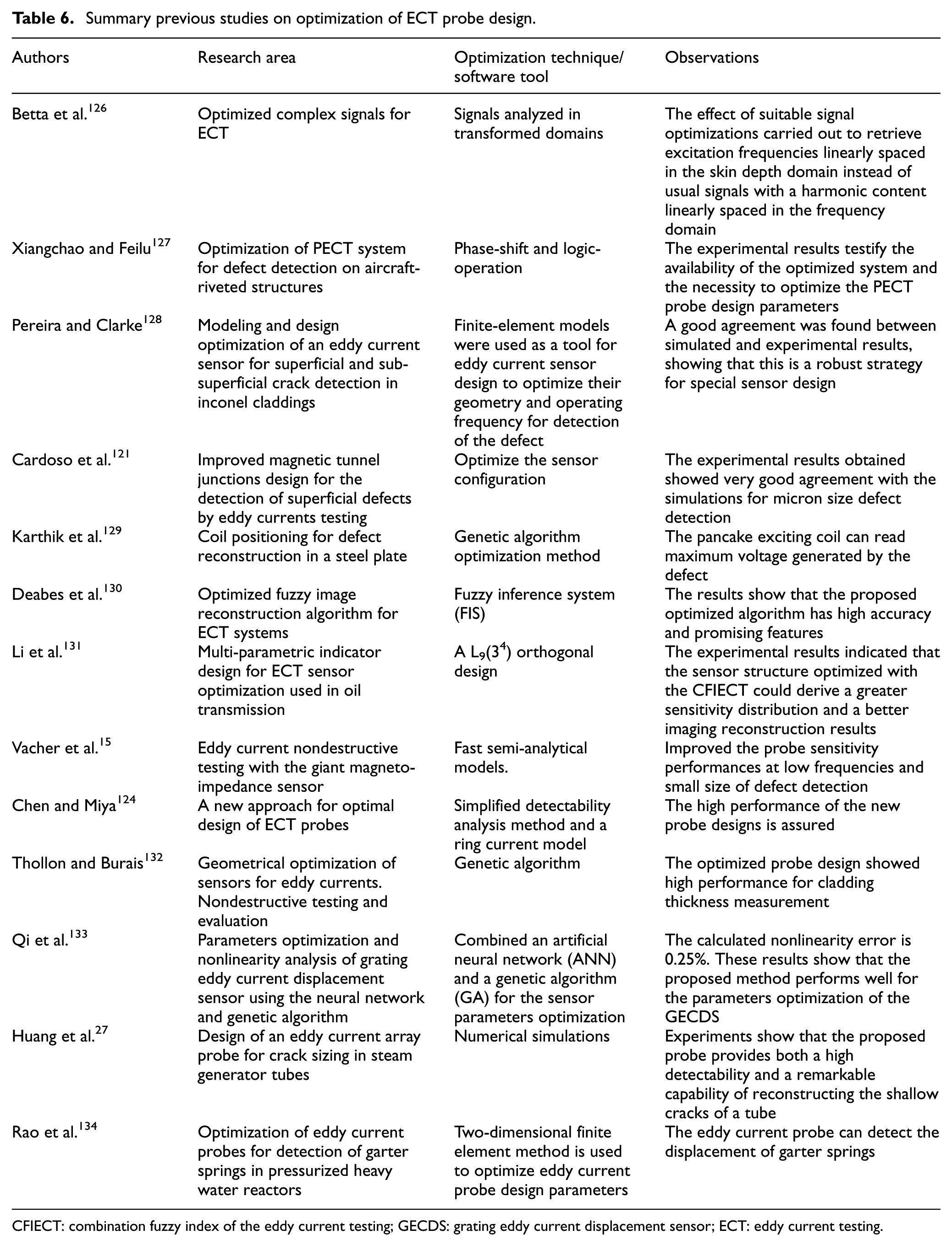
CFIECT: combination fuzzy index of the eddy current testing; GECDS: grating eddy current displacement sensor; ECT: eddy current testing.
Application of artificial intelligent in eddy current
GMR sensor is used in ECT to pick up the MF in the presence of the defect. As the mutual inductance between the coil and the specimen is sensitive to the lift-off, any changes in lift-off must be compensated for in order to achieve the accurate depth of defect measurements.
The fuzzy logic is instrumental for enhancing lift-off compensation. Artificial intelligent used is in many types of research in ECT. There are two common fuzzy inference methods: Mamdani’s fuzzy inference method and Takagi–Sugeno–Kang, a method of fuzzy inference. The output from Mamdani fuzzy inference system (FIS) can be easily transformed into a linguistic form as the inference result before defuzzification. 135 The main difference between Mamdani-type FIS and Sugeno-type FIS resides in the way the crisp output is generated from the fuzzy inputs. 136 While Mamdani-type FIS uses the technique of defuzzification of a fuzzy output, Sugeno-type FIS uses weighted average to compute the crisp output, 137 so the Sugeno’s output membership functions are either linear or constant, but Mamdani’s inference expects the output membership functions to be fuzzy sets which are appropriate for comparing the peak of sensors. Based on artificial intelligent technology, a lot of research has been done by many researchers about ECT, as shown in Table 7.
Intelligent technique in defect measuring.
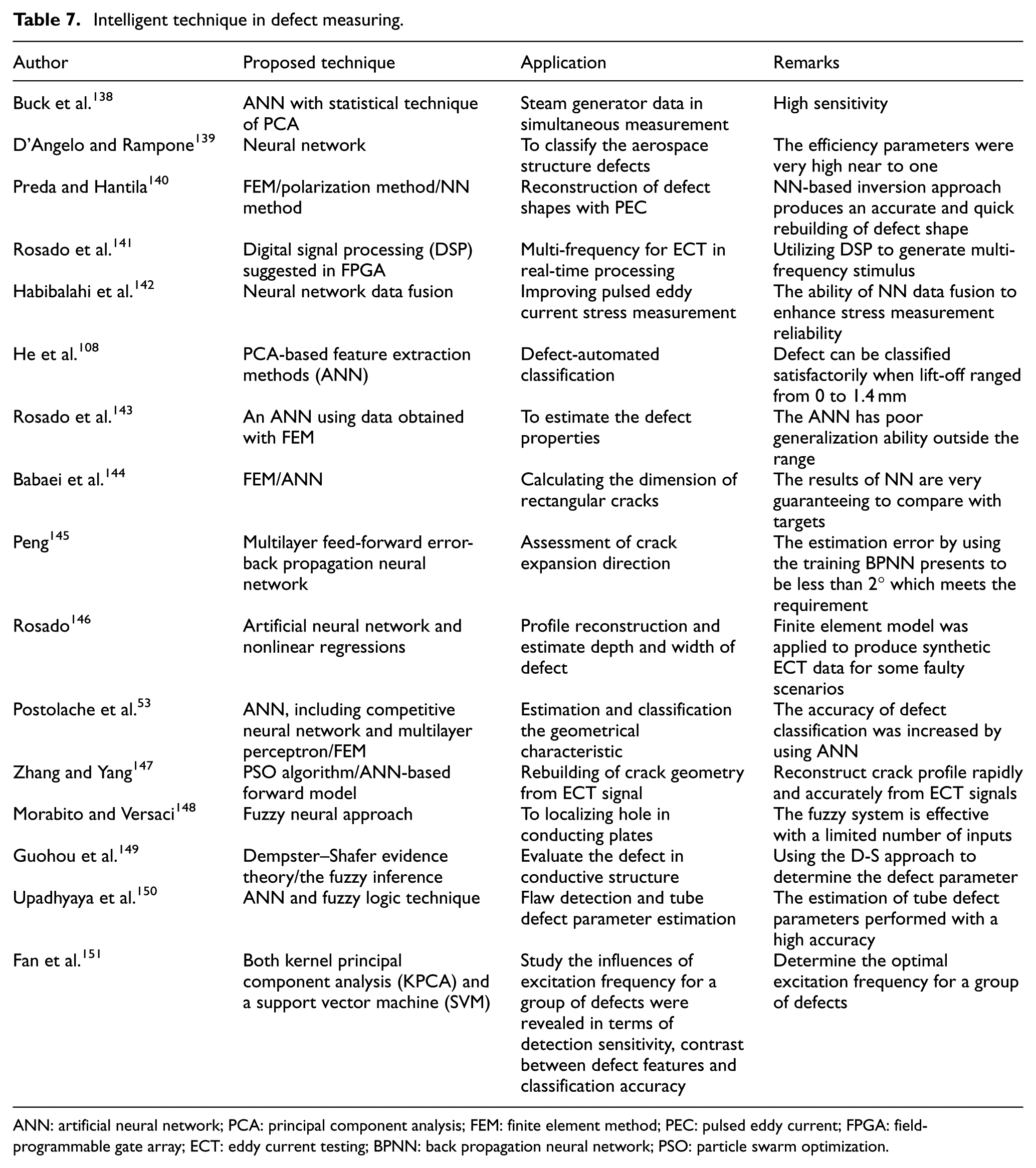
ANN: artificial neural network; PCA: principal component analysis; FEM: finite element method; PEC: pulsed eddy current; FPGA: field-programmable gate array; ECT: eddy current testing; BPNN: back propagation neural network; PSO: particle swarm optimization.
Conclusion
This paper introduces an overview of the eddy current probes structure and error compensation techniques to obtain an ideal measuring depth of defect for the material under test. There are two techniques to sense the change in MF air coil and magnetoresistance sensor. Air coil is less sensitive at low frequency which required to inspect the surface of pipe and plate. This particular paper also reviews the manufacturer in the industry to produce the commercial probes for practical tube inspection. In addition, compare the performance, detectability and the working principle of the bobbin probe, rotating probe and array probe for the pipe inspection was presented. The lift-off effects are the main factors affecting the ECT signal causing erroneous data interpretation. The lift-off effect is discussed in detail, ensuring that the measuring defect is right. Finally, briefly review different conventional and intelligent lift-off compensation.
Footnotes
Declaration of conflicting interests
The author(s) declared no potential conflicts of interest with respect to the research, authorship and/or publication of this article.
Funding
This work was supported by Huaiyin institute of Technology and University Malaysia Pahang under grant number RDU170379.