
Abstract
This paper formulates a coupling dynamic model for a flexible manipulator system with harmonic drive using experimental identification method. Parameters of the driven model of the harmonic joint and parameters of coupling vibration model of the flexible manipulator are identified. Accordingly, coupling dynamic models of the proposed system are obtained. Coulomb friction of the joint is identified by step current excitation and uniform rotation experiments at a low speed. Then, the transfer function model of the harmonic joint is established and identified by a pseudorandom binary sequence excitation. And predicted outputs of the obtained model are in good agreement with the experimental setup. Relationships between strain of the flexible manipulator and coupling torque are presented by theoretical derivation. Based on the theoretical model, transfer function from the angular displacement of the servo motor to the coupling torque is identified. Experimental results show this identified model match well with the proposed structure, both in the time and frequency domain. As a result, coupling dynamic modelling of the flexible manipulator system with harmonic drive is accomplished.
Introduction
The control of flexible manipulator system with harmonic drive is a key technology of flexible manipulator, which requires lots of study. The flexible manipulators have been widely applied in high-precision industrial equipment, spacecraft and medical instrument.1,2 To complete the tasks with high-precision and high-stability requirements, the harmonic drive is applied to drive the flexible manipulator. 3 The joints with servo motor and harmonic reducer of a flexible manipulator have many advantages such as low weight, good dynamic character, large transmission ratio and stable transmission. 4
The rigid-flexible coupling character of flexible manipulator system leads to elastic vibration in a movement. The movement of an object in the end of flexible manipulator is an inertia coupling which is constructed by a large displacement of system rigid body and a small elastic deformation. 5 As the harmonic factor introduced, the dynamic character of the system becomes more complicated.6,7 To enhance the operating precision and pointing accuracy, the vibration problem of the end of flexible manipulator should be reduced. 8 Both coupling and harmonic characters must be modelled to solve the vibration problem of manipulator.
A rational and precise dynamic model for system is necessary to high-precision drive control of a flexible manipulator. In current stage, many dynamic study of flexible manipulator only considered the mechanical character of system and aims at the vibration model of flexible manipulator.8,9 Feliu-Talegon and Feliu-Batlle 10 established a mass-concentrated model for manipulator and applied it to analyse the relationship between vibration character and motor torque. Sharma et al. 11 modelled a transfer function with a drive-joint torque input and a manipulator vibration acceleration output based on auto-regressive moving average exogenous (ARMAX) model. To figure out the friction of harmonic transmission constructed by harmonic reducer and servo motor, Liao et al. 12 studied the friction character of direct current (DC) servo motor based on LuGre friction model. Ahmad et al. 13 proposed a composite fuzzy logic control method for flexible manipulator. Cai et al. 14 proposed a nonlinear model which can be applied for flexible manipulator. Xu and Liang 15 proposed an electromagnetic harmonic movable tooth-drive system, which includes a comprehensive study about harmonic character. Shi et al. 16 modelled the harmonic-drive torque of robot joint with both theoretical and experimental study. Zhou et al. 17 studied the force decentralized robust control problem for constrained reconfigurable manipulator system, which the harmonic component is considered as a factor. Pacana et al. 18 studied the dynamic character of harmonic drive by finite element method. The works presented above have studied the harmonic character comprehensively, but the study in the coupling relation with system is still not enough.
There are some excellent works about coupling model and control of manipulator. Liang et al.19–21 and Sun et al. 22 studied the model of redundant parallel manipulator or robot in depth and proposed a series of control methods for parallel manipulator. The rigid model, flexible model, rigid-flexible model and electromechanically coupled dynamic model of parallel manipulator are all formulated and figured out by Liang and Sun. Ju et al. 23 formulated an electromechanical coupling dynamic model for servomotor-driven flexible manipulator with a simulation verification. However, these works considered the harmonic component little.
Some works in both coupling model and harmonic character have been presented. Kumar and Pratiher 24 studied the nonlinear model and vibration of a two-link manipulator, but their excellent work lacks experimental proof. Compared to previous works, this paper focuses on the coupling model of a harmonic-drive manipulator, which the harmonic character of driver and vibratory character of manipulator are studied in depth.
In this paper, the movement and vibration of flexible manipulator are studied based on the harmonic and coupling characters. A coupling dynamic model of harmonic drive is established, and the transmission gap of harmonic reducer, coupling character of motor and friction are all considered. The key parameters of the model are identified by an experimental method. The verification of models in this paper is verified through experimental method.
System description
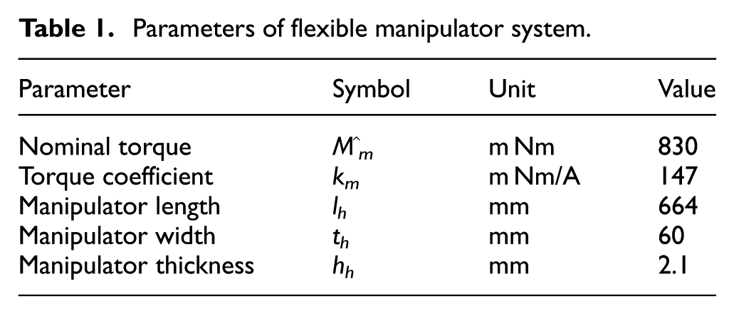
The schematic of the experimental system is shown in Figure 1 and the experimental equipment is illustrated in Figure 2. One end of the flexible manipulator is clamped above the harmonic-drive joints and the other end is hanged without external force or clamp. The drive part of the system consists of a DC servo motor and a harmonic reducer. The model number of the motor is ‘Maxon-EC-60’, the power of motor is 400 W, and the nominal rotate speed of motor is 2680 r/min. The performance parameters of flexible manipulator system are listed in Table 1. The model number of harmonic reducer is ‘CSF-20-50-2UH-LW-SP’ and the reduction ratio is 1:50.
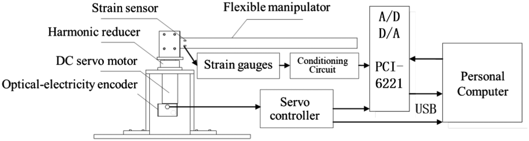
Schematic of the flexible manipulator system.
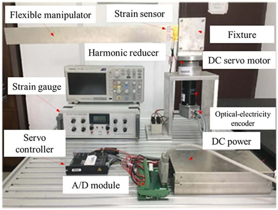
Experimental setup of the flexible manipulator system.
Parameters of flexible manipulator system.
In experiments, the LABVIEW control platform in personal computer generates drive-control sign and sends it to servo motor by A/D module, so that the servo motor can be controlled. The speed, position and electric current of the motor can be measured by an optical-electricity encoder and a Hall sensor in real time. The flexible manipulator will vibrate because of the effect of rigid-flexible coupling of system, while the strain sensor attached at manipulator sends the vibration information to the LABVIEW platform by D/A module.
The whole system in this paper includes one input and two outputs, which corresponds to the rigid rotation of system (includes harmonic character) and flexible vibration (includes coupling character). Two models will be formulated in this paper separately to reflect the relation of input of outputs of system.
System dynamic modelling and identification
Modelling and identification of system-drive model
According to the Newton dynamical equation, the torque equilibrium equation of harmonic-drive flexible manipulator system can be written as

where Г
motor
is the output torque of motor, V(t) is the input voltage of motor, of which the unit is V and controlled by servo controller, kt is the coefficient of conversion from volt to ampere, km is the coefficient of motor torque, θ is the angular displacement of motor which the unit is rad,
Friction torque is a key factor that affects the drive precision of servo motor, so it should be modelled and figured out. The viscous friction and coulomb friction are introduced, and the friction torque is modelled as follow

where B is the coefficient of viscous friction,

where Г c is an unknown constant torque coefficient, when the motor rotates uniformly in the same direction, the Гk is a constant term.
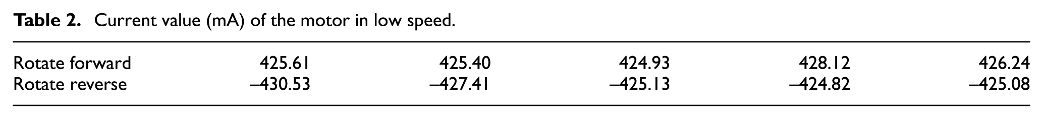
According to the Equation (2), Г f depends on the angular velocity of the servo motor and coulomb friction. When the motor rotates uniformly in a low velocity, output torque of motor is mainly used for overcoming the coulomb friction. To identify the Г c in experiment, motor rotates forward and reverse in 10 s respectively, which the velocity is set as 1 rad/s. The current value is recorded during the rotation and the average of multiple experiments results are applied to figure out coulomb friction torque. The Table 2 is the current values when motor rotates in 1 rad/s, to which the DC servo motor requires 425mA current to overcome the coulomb friction.
Current value (mA) of the motor in low speed.
To verify the effectiveness of the coulomb friction torque, a step current is applied to drive the motor, as illustrated in Figures 3 and 4: when the step current is not larger than 420 mA (forward step or reverse step current), the motor outputs little angular displacement and the motor can be regarded as static; when the step current reaches 430 mA (forward step or reverse step current), the motor outputs an apparent angular displacement. According to the torque coefficient km listed in Table 1, the coulomb friction torque can be figured out, and it is: Г k = 0.06248 N m.
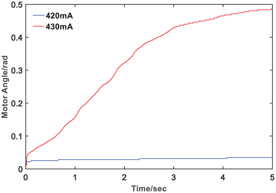
Motor angular with a forward step current.
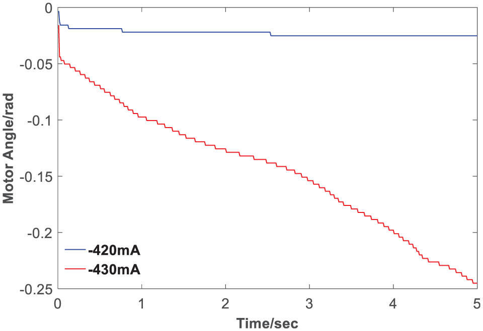
Motor angular with a reverse step current.
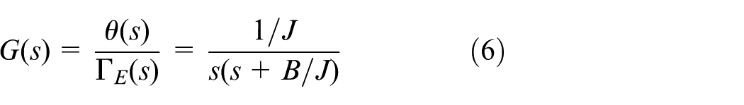
To identify the motor’s rotational inertia J and viscous friction coefficient B, the flexible manipulator is removed from the experiment equipment. The coupling of the flexible component and harmonic-drive joint (Г coup = 0), Laplace transformation is applied to equation (1) and the frequency-domain model can be written as

The transmission function diagram of harmonic-drive joint is illustrated in Figure 5. The coulomb friction is a nonlinear term and is always reverse to the rotation direction of motor, when the motor rotates. The model should be simplified so that the drive model of joint is easier to be identified. So a virtual torque Г E is introduced and defined as

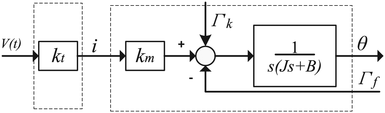
Schematic of the harmonic joint.
The second-order transfer function which is from Г E to θ is modelled as follow
The identifying precision of system parameters seriously depend on the correct selection of the input signal. The pseudorandom M-sequence signal is applied as the input signal V(t) for identification, the reasons are as follows: (1) the character of pseudorandom M-sequence signal is similar to the white noise, to which the signal has a uniform power spectrum 25 and (2) the signal is easy to implement, and the identifying precision can be guaranteed.
The servo controller works in current (torque) mode during experiment. A pseudorandom M-sequence with amplitude 1 V is applied as control signal for harmonic-drive joint, which is illustrated in Figure 6.
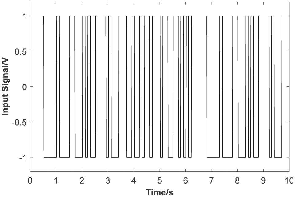
Binary pseudorandom M-sequence signal.
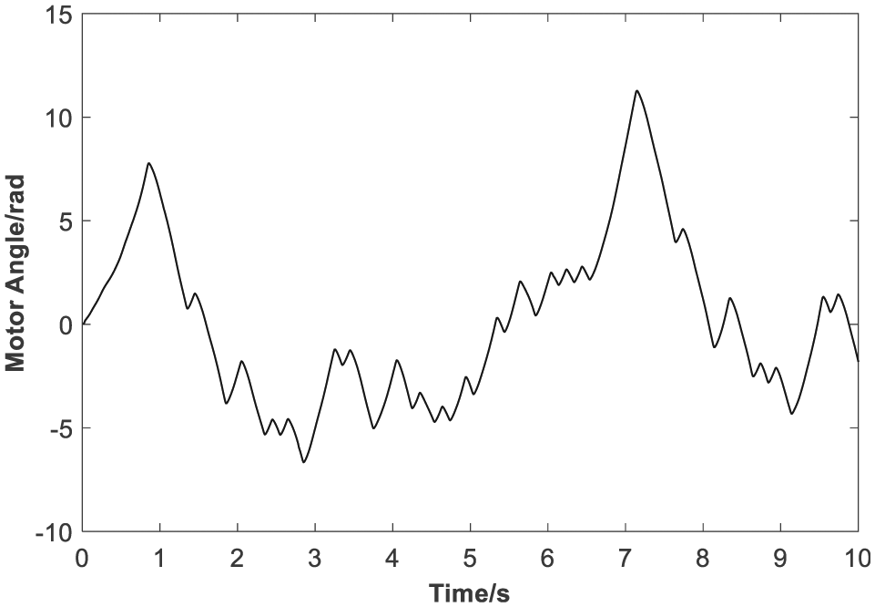
The coefficient of the voltage–ampere conversion is set as 500 mA/V, the output time of the voltage is set as 10 s, and the sampling frequency is set as 200 Hz. The angular displacement of motor is measured by optical-electricity encoder and the experiment result is illustrated in Figure 7.
Angular displacement of the servo motor.
The coulomb friction torque Г k is nonlinear according to equation (3), and the direction of Г k is changed when the θ changes. To identify the transfer function of system, the system model should be linearized. The coulomb friction torques are subtracted from Г E in equation (5) when the motor rotates forward or reverse, then Г E can be figured out and illustrated in Figure 8.
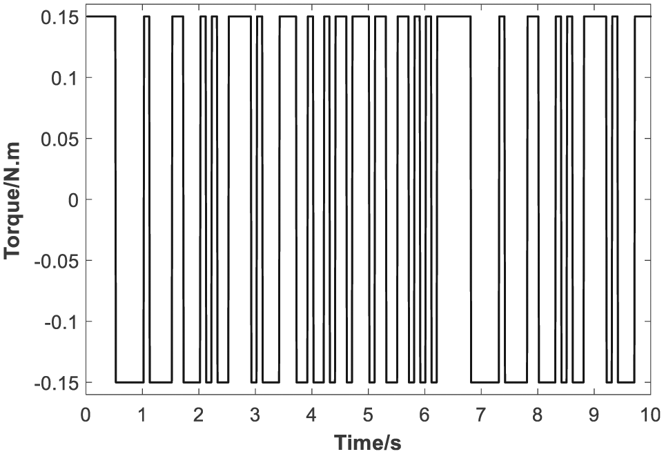
Values of virtual torque Г E .
Because the value of Г E (input) and the value of θ (output) are known, then the transfer function can be identified and the Identification Toolbox of MATLAB 26 is used. A nonlinear AutoRegressive eXogenous (ARX) model 26 is employed, and it identifies nonlinearities in system using dynamic nonlinearity estimators such as wavelet networks, tree-partitioning, and sigmoid networks.
The transfer function of drive component of system G(s) is calculated
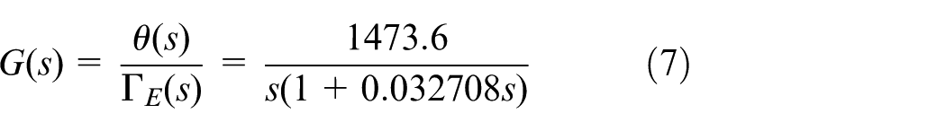
The output of G(s) is compared with the output of the real system, and the result is illustrated in Figure 9. The result shows that the output of G(s) fits the output of the real system well, so the model seems available for real system.
Comparison between experiment result and identified model.
Verification of system-drive model
To figure out how well the G(s) fits the real system, a verification test should be done. The output of G(s) and the real system is compared when the input is set as cubic polynomial signal in test, where the input signal (control voltage) is shown in Figure 10, and the comparison result is shown in Figure 11. Since the input is in cubic form, the output angular displacement of G(s) is in quintic polynomial form.
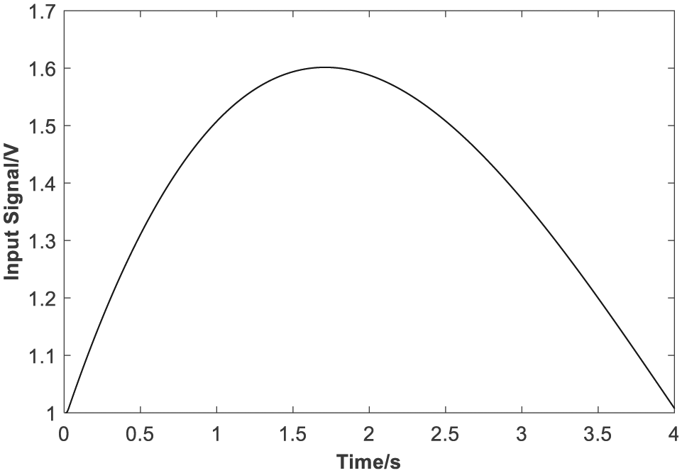
Input signal (control voltage) for verification.
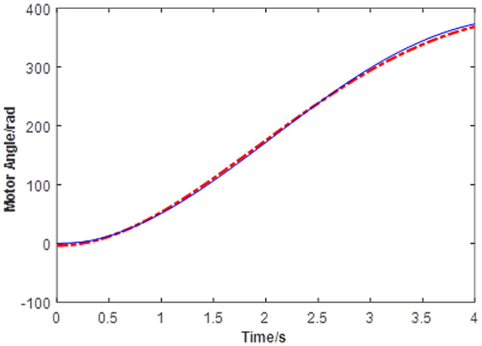
Comparison of angular displacement between G(s) and real system.
The result shows that (1) the output of G(s) also fits the output of real system well; (2) the identified model can be used for describing the relation between control voltage and angular displacement of motor and (3) the transfer function is available.
Identification of the flexible manipulator model
The modelling and identification of coupling vibration model of flexible manipulator
Since a precision-drive model G(s) has been obtained, the rigid-flexible coupling character of the system can be analysed. A model for the flexible vibration will be established. The servo motor is worked with a binary pseudorandom M-sequence input, and then the flexible manipulator will vibrate because of the rigid-flexible character of system. To describe the rigid-flexible character well, a transfer function model will be identified by experiment way. The input and output of the model are the angular displacement of motor θ(t) and vibration coupling torque of the manipulator Г coup , respectively.
Only the vibration in lateral direction is considered, since the vibration in axis direction of the manipulator affects little. The system coordinate is defined and illustrated in Figure 12.

Diagram of coordinate definition of the proposed system.
The x1o1y1 is a fixed inertial coordinate system, the xoy is a float coordinate system which fixes to the root of manipulator,
The coupling vibration torque of the manipulator Г coup is
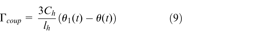
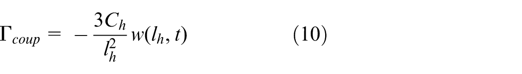
where Ch is the bending stiffness. Based on equations (8) and (9), the Г coup can be modelled as
The strain signal of the manipulator ϵa is transferred to a voltage factor by sensor and conditioning circuit, which the output voltage Vt is
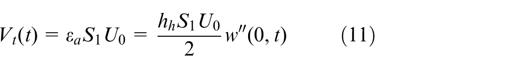
where S1 is the sensitivity coefficient of the sensor, U0 is the supply voltage of the circuit, and w″(0)) is the second derivative of the vibration displacement of the manipulator root to coefficient x.
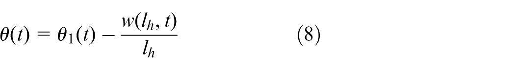
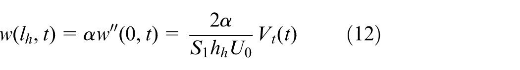
Based on the assumption of the small elastic deformation, the strain of the manipulator root and strain of the end of the manipulator has a linear relation. According to equation (11), w(lh, t) is modelled as
where
The transfer function H(s) is modelled as equation (14), to which the input and output are Г coup and θ, respectively
where ξi is the damping of the ith-order vibration modal and ωi is the angular frequency of the ith-order vibration modal.
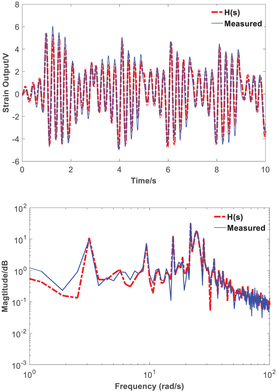
When the excitation voltage is set as binary pseudorandom M-sequence signal shown in Figure 6, the strain voltage Vt(t) is measured, and the result is illustrated in Figure 13.
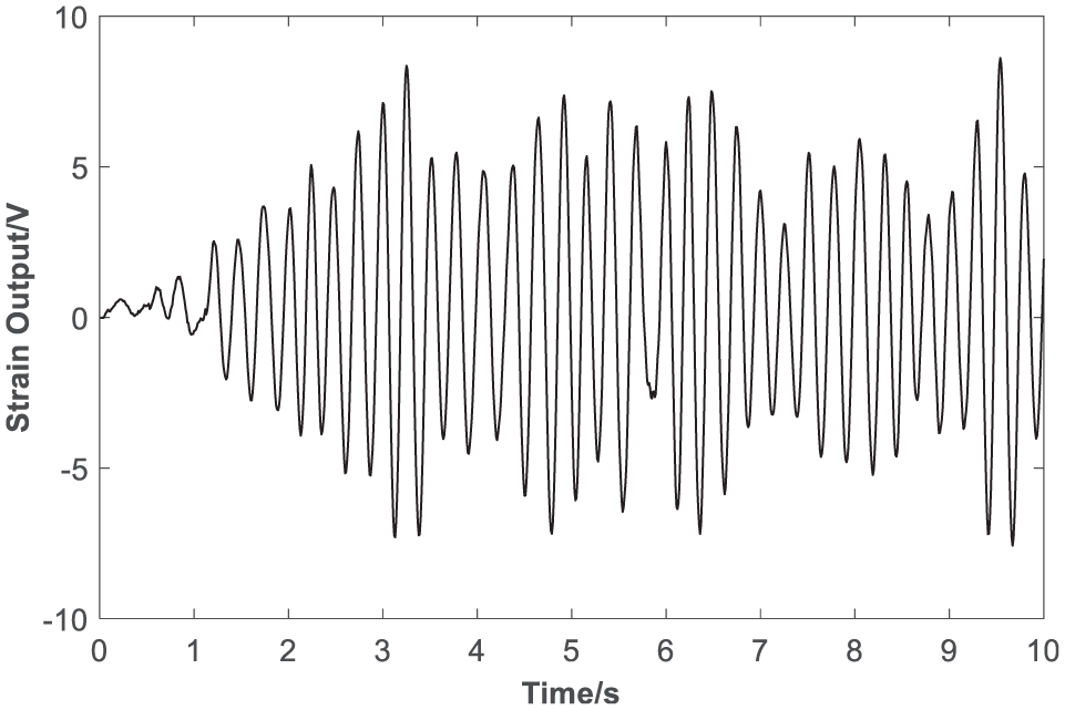
Strain output voltage.
Since the relationship between coupling vibration torque Г coup (t) and Vt(t) is linear, the relationship between Vt(t) and θ(t) can be also described by equation (14). The θ(t) illustrated in Figure 7 is set as input, the Vt(t) illustrated in Figure 13, and then the Identification Toolbox of MATLAB 26 is applied to identify the model of transfer function from θ(t) to Vt(t). The identification result is illustrated in Figure 14 with a comparison with the measure result.
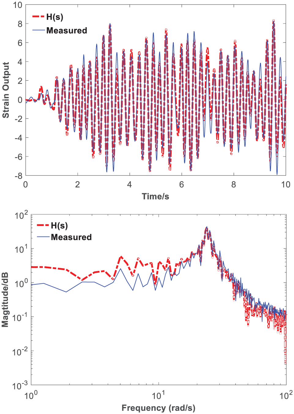
Comparison between identified model H(s) and experimental results in the time and frequency domain.
As illustrated in Figure 14, the output of the model fits the output of the real system well in time domain. The output of the model fits not well at 1–10 rad/s in frequency domain. However, it fits well at first-order frequency. Overall, the model seems precise and available at first-order frequency. Because the first-order vibration modal of manipulator is dominant, only first-order vibration model is identified. The first-order natural frequency is 3.8 Hz (23.85 rad/s), and the transfer function H(s) is
Verification of coupling vibration model of flexible manipulator
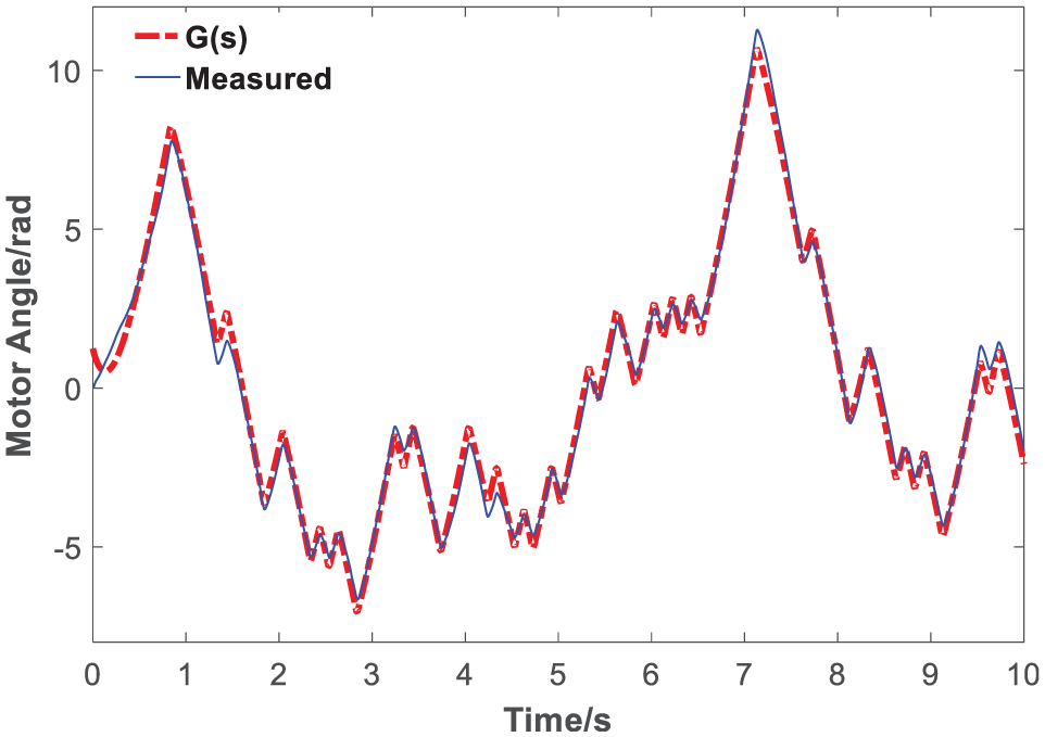
In order to verify how well the model fits the real system, the input θ(t) is controlled by a ladder voltage signal, and then the output is illustrated in Figure 15 with a comparison between the predicted and measured results.
Comparison of the output between identified model H(s) and experimental results.
Figure 15 shows that there is some deviation because of measure and noise error; however, the output of identified model H(s) can predict the trend of real system in time domain. The model fits the real system badly at 0–1 rad/s in domain, which shows that the precision of the model is low when the frequency is low. When the frequency is around the first-order natural frequency, the model fits the real system very well. Overall, we conclude that the identified model H(s) is available, and it can describe the vibration character of the system.
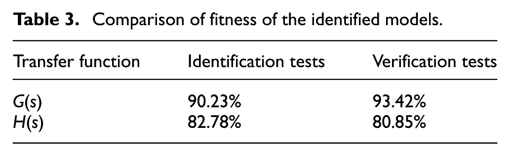
The quantitative evaluation of fitness of identification model is shown in Table 3, in which the results show that G(s) and H(s) fit the real system well, and the identification result is correct. The work of this paper can be the foundation to the implementation of precise location at the end of flexible manipulator.
Comparison of fitness of the identified models.
Based on the definition of G(s) and H(s), the transfer function of the system could be obtained by a cascade of these two models (see in Figure 16). It describes the transmission from the control voltage of motor to the vibration of manipulator.
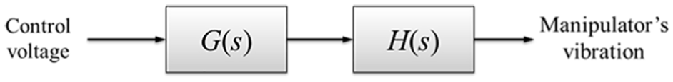
Diagram of the system.
Conclusion
This paper studies the problem of coupling dynamic modelling and parameter identification of harmonic-drive flexible manipulator. The harmonic and coupling characters of system are described through two transfer function models: G(s) and H(s). The G(s) is modelled by excitation of binary pseudorandom M-sequence signal, and the correction of the G(s) is also verified. The H(s) is modelled by experiment identification. The H(s) predicts the real system well in time and frequency domain, and its correction is verified. So the transfer function modelled in this paper is available for further study about system modelling and vibration reduction.
In future, more theoretical and experimental works on identification method will be done. The coupling model with harmonic drive will be studied further with more proof, simulations and experiments.