
Abstract
Modeling of aeroelastic system of wind turbine blade section based on chordwise rigid trailing-edge flap has been investigated. The flutter suppression of blade section exhibiting flap-wise bending and twist deformation is performed by equivalent sliding mode control. Aerodynamic expressions are based on the modified quasi-steady model which is attached to the influences of trailing-edge flap. The continuous equivalent sliding mode control algorithm based on quadratic feedback parameter is applied to realize flutter suppression, with displacements and velocities, control input of angle of trailing-edge flap and sliding mode function demonstrated. To facilitate the process of computer implementation, the discrete equivalent sliding mode control algorithm is discussed in detail, with better control effects and angle control of trailing-edge flap demonstrated. The quadratic feedback–based equivalent sliding mode control algorithm, including continuous equivalent sliding mode control and discrete equivalent sliding mode control, realizes the analysis of control effects based on feedback parameter with empirical adjustment coefficient. This provides schemes of not only theoretical simulation but also real-time implementation for the application of equivalent sliding mode control in different engineering projects.
Keywords
Introduction
Flutter suppression has been an important topic in the field of divergent instability of wind turbine blade for a long time. The two-dimensional (2D) blade section analysis has been widely used in quick study of flap-wise bending and twist deformation of wind turbine blade due to its simplicity and convenience.1–3 Aeroelastic instability analysis of individual turbine blade section subjected to flap-wise/twist motions was investigated in a earlier study, 1 with ONERA and Navier–Stokes aerodynamic model applied to analyze aeroelastic instability. Some structural control methods, based on trailing-edge flaps or microtabs, were used for aeroelastic control of blade section.2,3 Numerical study on closed-loop control of transonic buffet suppression by trailing-edge flap was analyzed. 2 Numerical investigation of flap-wise/twist vibration model of smart turbine blade section with microtab was investigated in professional literature, 3 with flutter control of blade section undergoing asymmetric limit oscillations investigated via microtab control scheme. Active intelligent load control equipped with microtabs was implemented by performance investigation based on linear quadratic regulator (LQR) and different conventional controllers. 4 Based on the approximate bending–torsion model of variable pitch excitation, the aerodynamic problem of a 2D airfoil with chordwise flexible flap under low Reynolds number aerodynamic conditions was studied in the work by Mathieu and Guy. 5 The aerodynamic performance of the flapping direction was analyzed based on the vertical Gurney flap in the work by Xie et al. 6 Based on the rigid trailing-edge flap of 2D airfoil, the effect of grooves on aerodynamic lift of trailing-edge flap structure was analyzed by Fluent software in the work by Li et al. 7 Lee and Su 8 adopted an experimental method to detect the aerodynamic coefficients of the bending–torsional motions of 2D airfoil based on the rigid trailing flaps (i.e. the segmented pendulum structure), but no theoretical study was made.
In addition, intelligent algorithms have recently been investigated in stability control of wind turbine blade section.9–12 Two types of model prediction control (MPC) algorithms9–11 were used to realize flutter suppression for unstable vibation of blade section. The pretwisted blade sectional structure incorporated with the structural damping under different pretwisted angles was controlled by MPC 9 to realize flutter suppression. The stability of integral sliding mode control (SMC) was investigated with Lyapunov stability criterion to make reduction in cost of wind energy for wind turbine. 13 The members of our research group have also carried out the limit cycle vibration analysis and the intelligent proportional–integral–derivative (PID) control strategy to analyze bending–torsional aeroelastic instability of the 2D blade in the previous work. 14
In this study, based on the segmented pendulum structure with revolute pair connection, a simpler chordwise rigid trailing-edge flap, the effect of theoretical aerodynamic model on the aeroelastic stability of blade section is studied. The aerodynamic model is derived and modified from the helicopter blade with chordwise trailing-edge structure in the work by Sahjendra and Woosoon. 15 Also, the control method of divergence instability under modified quasi-steady aerodynamic action is studied. Since SMC is often used to control the divergent instability of rotating body, 16 and the SMC itself is more suitable for tracking problems and solving the problem of uncertainty disturbance,17–19 this study first uses continuous equivalent sliding mode control (CESMC) to drive the angle of trailing-edge flap to track the aeroelastic instability motion. In the work by Liu, 17 the control of second-order underactuated systems was studied based on auxiliary feedback equivalent sliding mode control (ESMC). On this basis, considering the convergence performance of LQR, a new ESMC algorithm based on quadratic feedback parameter is proposed. Moreover, the chattering of the ESMC is restrained, and the better control effect is achieved.
Since the wind turbine system is mostly controlled by programmable logic controller (PLC), some intelligent control algorithms should be discretized to be implemented in PLC hardware. Hence, the discrete algorithm of SMC, including discrete equivalent sliding mode control (DESMC), has practical significance in engineering. To avoid the chattering problem in the reaching law–based discrete SMC and the generation of over-large control action in the DESMC, a new discrete SMC method based on non-smooth control was proposed. 20 Also, a robust output feedback controller was proposed for a class of uncertain discrete multiple-input multiple-output (MIMO) linear systems, and based on the combination of discrete SMC and Kalman estimator, ensuring the stability and an output tracking against the modeling uncertainties at large sampling periods. 21
In this study, a more refined DESMC algorithm, originally derived by Eun et al. 22 and suitable for chattering control, 23 and also based on quadratic feedback parameter proposed above, is investigated to realize flutter suppression of flap-wise/twist vibrations by adjusting the angle of trailing-edge flap. The numerical simulation results based on analysis of displacements and velocities and analysis of control input and sliding mode function fully demonstrate the robustness and superiority of the DESMC algorithm in flutter suppression, chattering suppression and instability control. Hence, several important characteristics of the control algorithms in this study can be summarized as follows: (1) the flutter suppression is focused on blade section with rigid trailing-edge flap driven by modified quasi-steady aerodynamic model; (2) both CESMC and DESMC are discussed in detail based on a new method with quadratic feedback parameter, with the control input being exactly the angle of trailing-edge flap; (3) owing to the large wind power system is mostly controlled by PLC, the refined DESMC algorithm is adopted, with better control effects demonstrated. Also, feasibility experiment of hardware implementation of DESMC algorithm is implemented by PLC hardware and PC via OPC Server in OPC technology.
Modeling of aeroelastic system
Consider the blade section exhibiting flap-wise bending and twist deformation. Figure 1 shows the blade section at a distance r = L/4 from the hub, with the length of the blade being L = 8 m. The flap-wise direction is denoted by z, and lead-lag direction is denoted by y. θ is the twist displacement and α is the angle of attack. The angle of trailing-edge flap is illustrated as β, wind speed is U = 10 m s−1, the chord length is c = 0.67 m and the length of rigid flap is lr = b − bc, with b being half chord length. V0 is incoming wind speed; λ = 1.2 is the speed ratio coefficient. The constant rotating speed is Ω = λU/L.
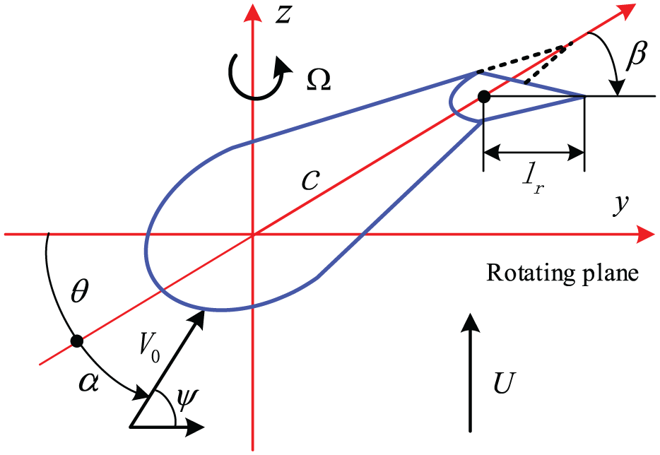
The 2D airfoil section and rigid trailing-edge flap.
Considering the cross-sectional model without trailing-edge flap in the work by Liu, 14 and ignoring the nonlinear and lead-lag vibration of the structure, the equations of flap-wise bending (z) and twist (θ) motions are obtained

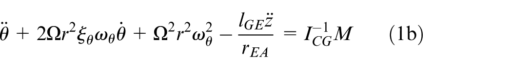
where the mass element of blade section is described by ρb = 50 kg m−1, the natural angular frequencies of motions in z and θ directions are described by ωz and ωθ, respectively; the corresponding damping ratios in z and θ directions are denoted by ξz and ξθ, respectively; the distance from the center of gravity to the center of the aerodynamics is lGE = c/6, the moment of inertia is ICG = 10 m kg; the parameter rEA can be described as:
A quasi-steady aerodynamic model suitable for aeroelastic wing with trailing-edge flap was shown in the work by Sahjendra and Woosoon. 15 The structural model therein was actually a simplified 2-degree-of-freedom (DOF) system. However, the change of the angle of trailing-edge flap can actually affect the aeroelastic system model itself. Therefore, the system analysis should focus on the system modeling with 3-DOF structure. Zhang and Behal 25 discussed in detail the modeling and analysis of the 3-DOF system. It is actually a nonlinear and non-rotating airfoil system, the solution of which requires complex technical operation.
In order to be suitable for the simplified analysis of 2-DOF system, the length of trailing-edge flap is limited in this study. When the length of the pendulum lr (the distance between the hinge point and the trailing edge of section in Figure 1) is less than or equal to c/6, and when the chord length is c and c − lr, respectively, the calculated flap-wise displacement z and twist displacement θ using Equation (1) under the condition of no pendulum have little difference; therefore, the length of the trailing-edge flap lr = c/6 is taken in this study. Note that the structural equation on the left side of Equation (1) is actually derived from the structure without trailing-edge flap in the work by Liu. 14 Therefore, after the length lr is limited, it can be directly used in the analysis of this study, so that the influence of trailing-edge flap on the structural model of blade section can be ignored. Hence, a 2-DOF aeroelastic system can be obtained, which greatly simplifies the analysis—from a nonlinear aeroelastic system to a linear aeroelastic system—so that subsequent ESMC analysis can be carried out.
In the work by Sahjendra and Woosoon, 15 the bending/twist coupling motions of 2D elastic wing were analyzed, and active flutter control based on rigid trailing-edge flap was realized. Based on the principle in the work by Sahjendra and Woosoon, 15 the following steps are performed in this study: the wind speed in the original pendulum-excitation aerodynamic equation is changed to incoming wind speed V0 of wind turbine, the variable pitch angle therein is replaced by attack angle α of wind turbine here and the modified aerodynamic term of the pendulum excitation is added via the relative rotation. When all these items are integrated into the aerodynamic force (moment) of Liu and Chang, 24 the new aerodynamic forces suitable for the design of rigid trailing-edge flap structure of rotating wind turbine are obtained as follows
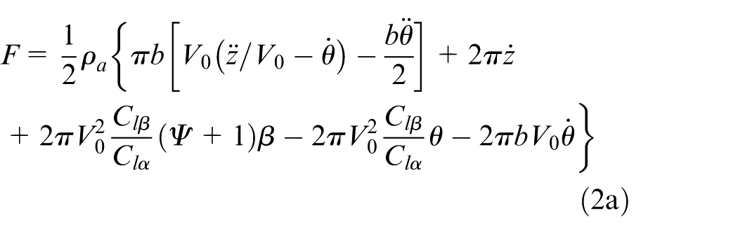
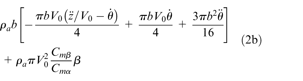
where ρa is the air density; the lift and moment coefficients per angle of attack are denoted by
In particular, for lr = c/6, it is exactly the value of lr = b − bc, as implied by Sahjendra and Woosoon
15
and Zhang and Behal.
25
Therefore, the coefficients per angle of trailing-edge flap,
To implement subsequent control processes, insert Equation (2) into Equation (1) and convert it into a first-order system 24 to obtain the following

where
ESMC
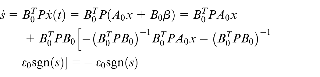
The sliding variable is selected as follows

where P is a 4 × 4 positive-definite matrix, with the design of which s can be zero.
The equivalent controller, that is, the control angle of trailing-edge flap β, with a small positive-limiting coefficient ε0 (in practical engineering problems, one might as well let ε0 = 0.15), can be designated as follows
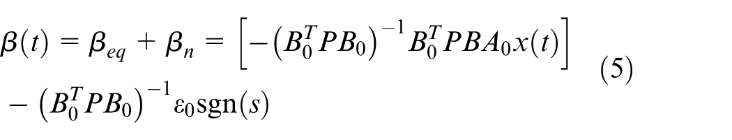
Select the Lyapunov function V = s2/2; then
and there exists

It should be noted that in this ESMC control, quasi-SMC 17 is used; saturation function is used instead of symbol function in ideal sliding mode; and switching control is adopted outside boundary layer Δ. Feedback control in the boundary layer can attenuate the chattering phenomenon in a certain sense. In this design, Δ = 0.05.
Analysis of CESMC
To solve for symmetric positive-definite matrix P, the controller β is rewritten as follows

where v(t) = Kx + βeq + βn. Especially in this study, to make full use of the convergence advantage of the LQR controller, the feedback value of the LQR controller
There exists such a K that

Select the Lyapunov function V = xTPx; then
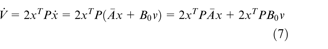
When t > t0, there exists

Then, the stability of the closed-loop system can be guaranteed by only proving that

In Linear Matrix Inequality (LMI) design, 17 a symmetrical matrix P can be obtained and easily guaranteed.
Analysis of DESMC
In order to facilitate the realization of computer control in practical industrial applications, the discrete algorithm of ESMC needs to be further developed. Consider the continuous system of Equation (3) and convert it into a discrete system, to obtain

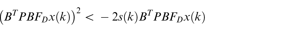
Let switching function s satisfy s(k) = BTPx(k), herein, P is the specific symmetric positive-definite matrix designed before. When the discrete system enters an ideal sliding mode, s(k) satisfies s(k + 1) = s(k); then
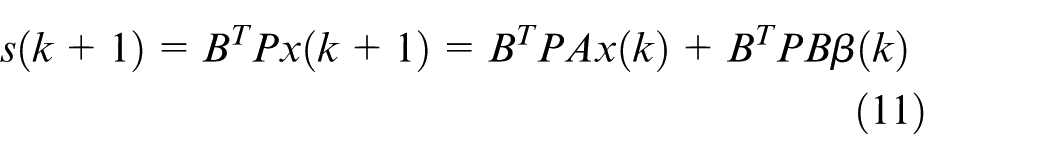
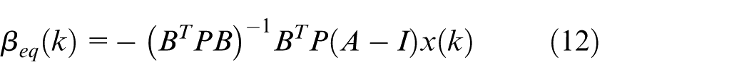
At this point, β(k) is βeq(k); thus, the equivalent control can be obtained as follows
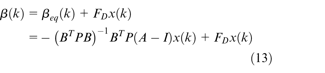
In order to improve the accuracy of the discrete algorithm and reduce the chattering phenomenon caused by the discretization process, a discrete–sliding mode variable structure control law23,26 based on equivalent SMC can be expressed as follows
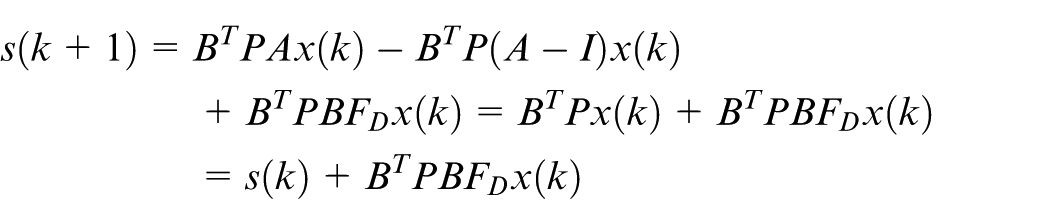
Select the Lyapunov function V(k) = s(k)2/2, and the stability analysis is given as follows. By inserting Equation (13) into Equation (11), the following can be obtained
then
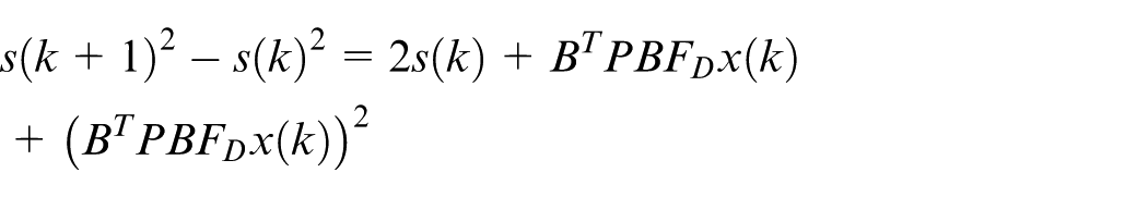
To make s(k + 1)2 − s(k)2 < 0, one only needs to satisfy
that is
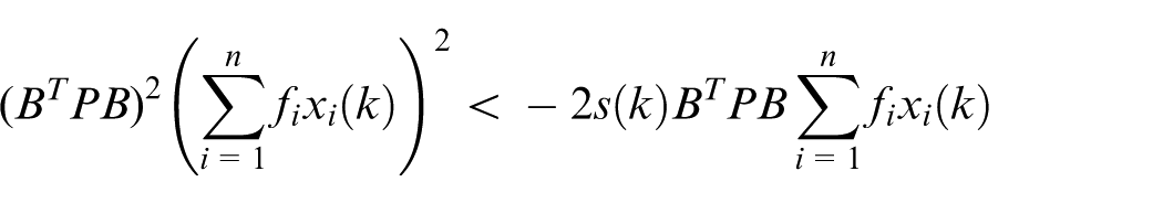
Let |fi| = f0, f0 > 0; then, for every i, there exists 23
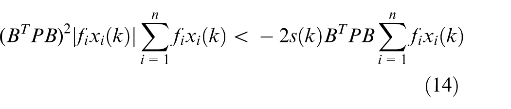
Let define
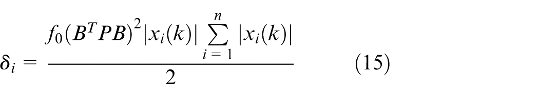
By inserting Equation (15) into Equation (14), one can obtain the following

By considering Equation (16), the value of fi can be determined by comparing s(k)BTPxi(k) and δ. Hence, the following inequality holds
In conjunction with Equations (15) and (17), to make s(k + 1)2 − s(k)2 < 0, one only needs to satisfy
To sum up, the control process of DESMC is realized by three formulas of Equations (12), (13) and (18). In practical engineering problems, one might as well let f0 satisfy
Numerical simulation and discussion
The related simulation parameters are defined as follows: initial condition is x(0)[0.1 0.1 0.1 0.1]T, sampling time is ts = 0.01 s and simulation solver is ode45. In this study, based on the structural and aerodynamic parameters given in section “Modeling of aeroelastic system,” a case of divergent instability of the aeroelastic system is presented and demonstrated. The two types of ESMC algorithms based on different performance parameters of the empirical adjustment coefficients, q, are also discussed in detail to realize flutter suppression in this section.
Divergent case and LQR control
The LQR is often used to analyze vibration control of rotating structure. Figure 2 shows the uncontrolled displacements of both flap-wise displacement (z) and twist deformation (θ), and those controlled by LQR controller under the condition of the structural and aerodynamic parameters mentioned above. Herein, the weighting factors Q and R in LQR controller can be defined as follows: Q = [100 0 0 0, 0 99 0 0, 0 0 98 0, 0 0 0 10], R = 0.01.
The uncontrolled displacements of both flap-wise displacement (z) and twist deformation (θ) and those controlled by LQR controller.
The uncontrolled displacements exhibit unstable states, especially for displacement (z) with vibration amplitudes more than the blade section radius r = L/4 = 2 m within time of 1 s, which is a state of extremely divergent instability from the point of view of numerical simulation. The controlled cases with LQR in Figure 2 present the states of convergent stability on the trend of the whole time domain fluctuation. However, from the point of view of steady-state value of displacement (z), the amplitude is still too large and exceeds the radius r = 2 m, which in fact belongs to a kind of divergent unstable state. As can be seen, the LQR control results have relatively large offsets, which is actually not conducive to practical engineering applications.
Flutter suppression based on ESMC
Based on the empirical adjustment coefficient q, which is embedded in the quadratic feedback parameter K in Equation (6), Figure 3 illustrates the comparisons of CESMC control effects including displacements, velocities and control signals, under different coefficients of q = 1, q = 10 and q = 100, respectively. Compared with the uncontrolled displacements of both flap-wise displacement (z) and twist deformation (θ), and those controlled by LQR controller in Figure 2, the displacements controlled by CESMC show excellent convergence state and stability with smaller amplitudes of vibration. Especially for the case of q = 100, the flap-wise displacement (Flap z) shows a smoother vibration performance. As for the fluctuations of velocities, the control results under the three coefficients are basically in the same state, accompanied by moderate amplitudes of vibration.
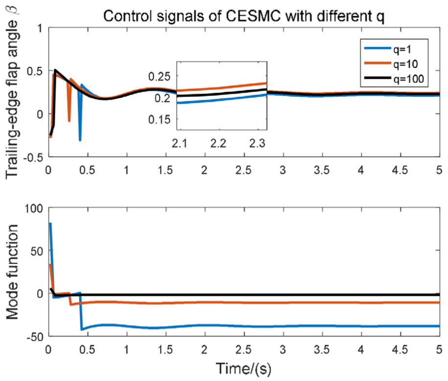
The comparisons of CESMC control effects including displacements, velocities and control signals, under different coefficients of q = 1, q = 10 and q = 100, respectively.
From the control signals, the control input of trailing-edge flap angle β under q = 100 shows the superiority of excellence, while the input signals under the other two coefficients (q = 1 and q = 10) show the peak beat of angle β within 0.5 s. This also reflects the inherent chattering defect of SMC algorithm (indicating that the buffeting frequency will be larger if the boundary layer Δ control is not used). This angle β is usually driven by actual mechanical structures, such as pneumatic transmission systems, so its smoothness is essential.
In addition, the superiority under q = 100 is also reflected in the fluctuation of sliding mode function with a smaller initial vibration amplitude and a smaller steady-state value close to zero, which are in complete agreement with the design requirements of Equation (4).
It should be stated that the simulation results show that when q is greater than 100, the control effect will gradually become worse; especially when q = 1000, the control input signal itself is in a completely divergent state. This may be due to the fact that the value of q is too large, which may make it difficult to match a symmetric positive-definite matrix P. So, q needs to be valued and defined within a certain range. The empirical property of q also makes the rationality of the CESMC algorithm greatly reduced, which is also the purpose of succedent study for DESMC algorithm. The empirical property of q also makes the rationality of the CESMC algorithm greatly reduced, which is also the purpose of study of DESMC algorithm.
Based on the different empirical adjustment coefficient q mentioned above, Figure 4 illustrates the comparisons of DESMC control effects including displacements, velocities and control signals, under different coefficients of q = 1, q = 10 and q = 100, respectively. Compared with the controlled displacements of both flap-wise displacement (z) and twist deformation (θ) in Figure 3, the displacements controlled by DESMC demonstrate better control effects, especially with a smoother vibration associated with the flap-wise displacement (Flap z). The advantage of smoothness is also reflected in velocity fluctuation in flap-wise direction and control signal fluctuation of angle β. As for the sliding mode function, the fluctuation of the latter is more stable and the amplitude is smaller (only 1/1000 of the former). It is further shown that the control of DESMC is superior to the control of CESMC in chattering suppression.
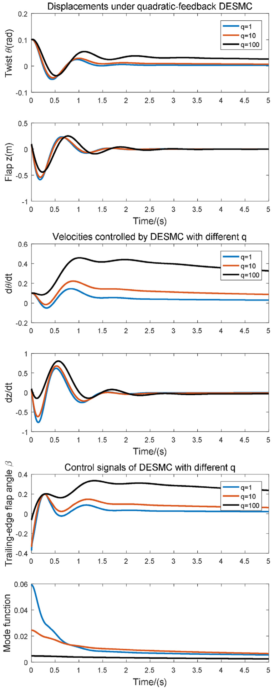
The comparisons of DESMC control effects including displacements, velocities and control signals, under different coefficients of q = 1, q = 10 and q = 100, respectively.
Especially, when the control signal β is smooth and has no sudden impulse (as depicted in Figure 3), it means not only the smoothness of the control process but also the protection of the controller hardware and control system equipment from the overload shock.
As for the comparisons of control effects under different q values, it can be seen that except for sliding mode function curve, almost all other project curves (for not only displacements and velocities but also control input of angle β) show positive performances under condition of q = 1, compared with the conditions of the other two coefficients (q = 10 and q = 100). This also means that there is no need to design the empirical coefficient q separately for the DESMC algorithm implemented by the computer; that is, the quadratic feedback parameter K is directly equal to K0 of the LQR controller, which is the second advantage of the discrete algorithm.
It should be noted that the definition of K is for the purpose of determining the final symmetric positive-definite matrix P, so that the controlled β in Equations (12) and (13) can be computed in both CESMC and DESMC algorithms.
In addition, the fluctuation frequency of the control input signal β and the energy and power it consumes are also the indexes to measure the control performance. For the optimal case under q = 100 of CESMC algorithm and the optimal case under q = 1 of DESMC algorithm, Figure 5 illustrates the amplitudes of frequency spectrum (ASF) of the control input β and the amplitudes of power spectrum (APS) of the control input β for the two algorithms, respectively. N data points are contained in the time domain 0–5 s. It picks up Fs = 128 sampling points at equal spacing within 0–5 s with sampling frequency interval f0 = Fs/N. Periodic graph method is used for APS analysis.
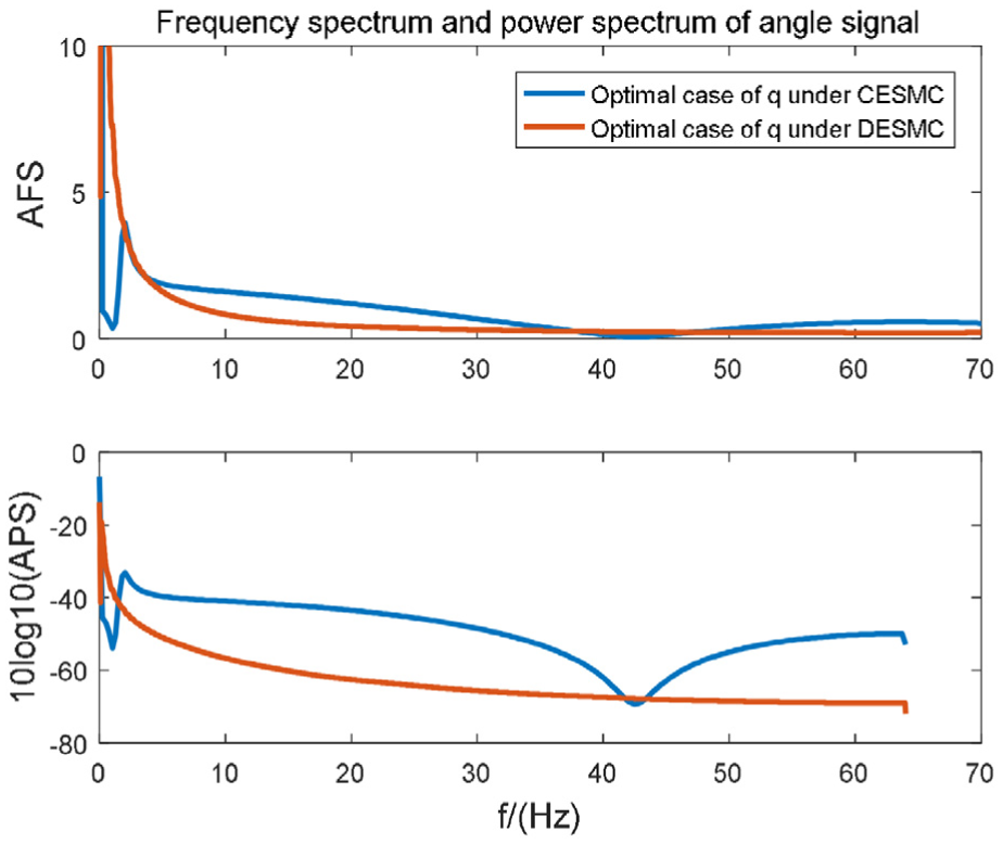
The amplitudes of both ASF and APS of the control input β for the optimal case of q under both CESMC and DESMC algorithms.
In the frequency range 0–70 Hz, the maximum amplitudes of both ASF and APS for the two algorithms are basically equivalent. However, in the frequency range 5–70 Hz, whether for ASF or APS, the amplitudes of DESMC algorithm are smaller than those of CESMC algorithm, and the fluctuations are more stable. In particular, at f = 2 Hz and f = 42 Hz, the CESMC algorithm has sudden fluctuations, which in the actual project will bring about the shock and vibration of the mechanical hardware or the sudden change in the power of the circuit element, which should be avoided.
In addition, in view of the theoretical analysis of 2D airfoil discussed in this paper, it is impossible to build the experimental platform because it is impossible to realize the independent 2D airfoil structure in the experiment, but the hardware implementation of 3D pendulum structure is completely feasible.
Assuming that the longitudinal length of the pendulum structure occupies only a part of the blade span, for example, the pendulum structure is located in the middle part of the span, the 2D wing pendulum structure can be designed with reference to Figure 6. The point D on the pendulum structure can be hinged with the 3D blade body structure on both sides. In order to realize the forward positive deflection, the point D can be located on the upper side of the horizontal chord. A and B are two retractable piston-rod cylinders, respectively. The right ends of the two piston rods are hinged and linked with the point C by two equal length connecting rods, respectively, and the C point is the fixed point on the pendulum structure. When the system is working, the two cylinders are driven by the pneumatic proportional valve (electric proportional valve), respectively, which realizes the reverse synchronous action of the two piston bars; that is, the B bar retracts when the A rod is out, which pushes the C point to rotate at a finite angle around D point to achieve the change of the trailing-edge flap angle.
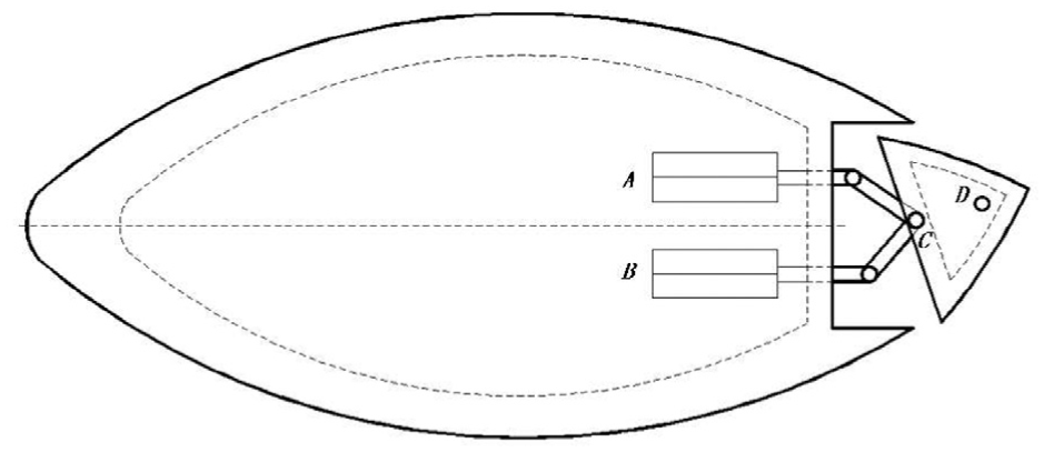
Schematic diagram of trailing-edge flap of 2D airfoil structure.
It should be noted that pneumatic transmission rather than hydraulic transmission is used here because the pneumatic pipe is flexible and can be distributed along the length of the hollow blade. At the same time, the pressure proportional valve can also realize the continuous proportional control. According to the magnitude of the angle signal, the equivalent displacements of the piston rods can be converted and output in the contrary directions. In addition, when the positions of the fixed hinge points D and C are changed, different adjustments of the maximum allowable value of the trailing-edge flap angle can be realized. In general, this angle, the control input β, does not exceed 30°, which coincides with the results shown in Figure 4.
There is another point that needs to be clarified. In this design, when the turbulence intensity is constant and the surface roughness is specific, the wind speed is not more than 10 m s−1 in the case of turbulence fractal characteristics within 80 m height. 27 The simulation results show that the proposed control algorithm can meet all the conditions when the wind speed is below 20 m s−1.
Feasibility experiment of hardware implementation of DESMC algorithm
The basic advantage of DESMC algorithm lies in the computer execution of discrete algorithm. The wind turbine blade system is mostly controlled by PLC hardware. Feasibility of controller hardware implementation of control algorithm should be verified. An experimental platform in Figure 7, based on OPC technology, 28 can meet this requirement. The hardware-in-the-loop simulation technology is used by OPC Server that connects PLC and MATLAB simulation environment. Figure 7(a) demonstrates the feasibility experiment scheme of hardware implementation of DESMC algorithm. The aeroelastic system model is run in MATLAB simulation environment in PC. The PLC hardware to which HMI hardware is connected to display the signal outputs runs the entire DESMC algorithm. The signal transmission between PLC and PC (connected by PC-PPI cable) includes two parts: initial value transfer (①) and process value transfer (②). The OPC Server is built between MATLAB and PC Access software. 28 It can communicate with any standard OPC client and provide data information. The OPC Server uses OPC Read operation and OPC Write operation to transfer data, respectively. Under MATLAB environment, there are OPC Read and OPC Write modules in SIMULINK toolbox, which can be called directly.
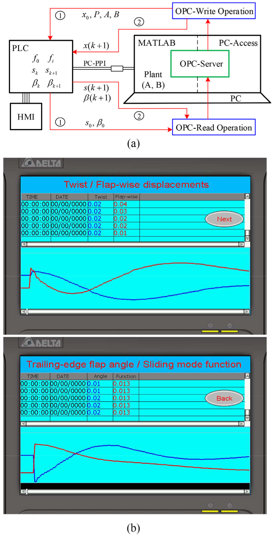
The feasibility experiment of hardware implementation of DESMC algorithm under the optimal case of q = 1: (a) the feasibility experiment scheme and (b) the experimental results (displayed in HMI) of twist/flap-wise displacements and the control signals within time 1.3 s.
The process of establishing OPC Server is summarized as follows. First, connect the PLC in PC Access to set the PLC name such as NewPLC. Then, create the item project (as a member function of NewPLC), in which the data addresses defined is the type of double word, with data type being real type. Second, a type of registration (using command “opcregister”) and configuration (using command “opctool”) mechanism needs to be run in MATLAB. During configuration, one only needs to connect to the corresponding address defined in the PC Access and then OPC Server can be built.
Figure 7(b) shows the experimental results (displayed in HMI) of twist/flap-wise displacements and the control signals including the trailing-edge flap angle and the sliding mode function under the optimal case of q = 1 of DESMC algorithm. For comparison purpose, Figure 7(b) shows only the time domain responses within 1.3 s.
Compared with the results within time 1.3 s of q = 1 of DESMC algorithm in Figure 4, the responses displayed in Figure 7(b) reveal an excellent agreement. A slight difference in curve fluctuation is due to the limited sampling time of the PLC (including HMI) hardware, with a minimum sampling interval of 0.1 s.
In Figure 7(b), note that the horizontal axis is a time axis and the timing of the scale is recorded when the PLC is powered on. The HMI used in this design is, in fact, a touchscreen hardware called DELTA-DOP. HMI can not only display the fluctuation of real-time curve but also display the instantaneous value of real-time data. The PLC hardware used here is Siemens S7-200 CPU.
Conclusion
Aeroelastic modeling of 2D wind turbine blade section based on chordwise trailing-edge flap has been investigated. The flutter suppression of blade section exhibiting flap-wise bending and twist deformation is realized by ESMC algorithms. Some results can be outlined as follows:
The equations of bending/twist coupling motions are made by referring to and extracting from an elastic wing in the work by Sahjendra and Woosoon. 15 Some parameters have been modified and rebuilt and are integrated into the aerodynamic force (moment) of Liu and Chang 24 to realize modeling of aeroelastic system.
Two types of ESMC algorithms are investigated, including CESMC and DESMC, which are both based on a kind of quadratic feedback parameter K. In view of the different structural coefficients, q, in K, the responses of displacements, velocities, the control inputs and mode function signals are discussed in detail, and the flutter suppression is realized. At the same time, the advantages and disadvantages of the two ESMC algorithms are demonstrated in different conditions.
The advantage of DESMC algorithm over CESMC lies in that, first, it is easy to be realized by computer; second, it has higher precision and can suppress chattering phenomenon; in addition, there is no need to choose different values of q because when the value of K is directly equal to the feedback controller value of LQR, the control effect is optimal.
Feasibility experiment of hardware implementation of DESMC algorithm is implemented by PLC hardware and PC via OPC Server in OPC technology. Hence, the DESMC algorithm has certain practical significance.