
Abstract
Background:
Active lateral suspension (ALS) technologies have been well developed for several decades, but they have not been widely used in service operation due to relatively high costs for implementation and maintenance and concerns about fail-safe. Therefore, this paper suggests a more practical approach for the active suspension system, designed to achieve target performance with easy implementation and maintenance and high fail-safe.
Methods:
The control performance target and actuator type are determined from the vibration energy that the ALS has to absorb along the weight function for ride quality evaluation. The installation position of actuator and sensor is decided to decrease the time that it takes for field engineers to check the actuator for maintenance. In addition to fail-safe function of ALS system, conventional hydraulic lateral damper is installed in parallel with ALS to reduce the concern about fail-safe of the ALS.
Results:
Through the roller rig and filed tests, the performance of the proposed ALS was validated. Lateral ride quality was improved 7.1dB and 6.7dB in the roller rig test and field test, respectively. The fail-safe strategy was also verified during the filed test.
Conclusion:
Test results show that the suggested ALS is designed appropriately and can be used in practical implementation.
Introduction
As railway demands have increased and rail networks have expanded, railway operators face the difficulty of high maintenance costs. Requirements placed on railway vehicle manufacturers for riding comfort, running safety, and operating speed are continuously increasing, even though track conditions are getting worse. In the case of riding comfort, the requirement can be classified in two ways: improving passenger comfort at the same vehicle speed and track conditions or maintaining passenger comfort despite increased vehicle speed or worse track conditions. Conventional railway vehicle design has reached the limits of its ability to meet these requirements. Active suspension systems have been developed as an alternative measure, and some semi-active and full-active secondary suspension systems have been implemented in Europe1,2 and Japan.3,4 Of the active suspension technologies used by railway vehicles, tilting is the most famous. Tilting technology can reduce the centrifugal force that causes passengers to feel outside acceleration in curves. The hold-off device (HOD) was developed to reduce the quasi-static displacement between carbody and bogie in curves. The concept was already introduced in the 1990s; 5 however, it was only recently commercialized for use in tilting systems. 2 Active lateral and vertical suspensions have been developed to reduce the acceleration transferred from track irregularities up to the carbody. Generally, an active vertical suspension (AVS) is relatively more difficult to develop than an active lateral suspension (ALS) in railway vehicles, since the vertical control frequency range is higher, and the control force might excite the carbody flexible mode, such as bending mode. Hence, although ALS has been adopted in a few high speed trains and in certain countries,3,4,6 AVS has yet to be introduced.
As mentioned earlier, even though ALS technologies have been well studied for several decades and commercialized in certain countries, they have not been widely used in service operation due to relatively high costs for implementation and maintenance and concerns about fail-safe. Thus, a more practical approach for ALS system design is required in order to attract railway operators.
This paper suggests a practical approach for ALS systems for easy implementation and maintenance with high fail-safe. The design process of actuator type and specifications is introduced. Control and fail-safe strategies are also described. Test results in the laboratory and on tracks show the suggested ALS system can be applied to conventional bogies with minor changes in their original design.
Design of the ALS system
Determination of ALS control bandwidth
The decision of control bandwidth is one of the fundamental processes in active control design. ALS control bandwidth can be specified by investigating the evaluation guidelines of ride quality and dynamic characteristics of railway vehicles. In general, guidelines according to UIC 513 or ISO 2631 are used. Korea also has its own evaluation guideline, KS R 9216. However, weight functions for evaluating lateral ride comfort are very similar among these guidelines.7–9 In KS R 9216, lateral acceleration signal filtered from the weight function is calculated as root-mean-square (RMS) value and converted to decibels (dB). In this paper, KS R 9216 is used to evaluate the lateral ride quality since the expression of dB is more intuitive.
As shown in Figure 1, the weight function has a maximum at 1 Hz. Assuming that the lateral acceleration of the carbody has a uniform amplitude, A, independent of its frequency, it can be expressed as Equation (1) at a certain frequency f, and the energy dissipated by ALS in a cycle of Equation (1) can be expressed as Equation (2) when the ALS plays a role of viscous damper to absorb the vibration energy


Here, ceq is the equivalent damping coefficient of ALS. Total dissipated energy can be calculated by integrating Equation (2) along the frequency. For an ideal ALS, the vibration energy’s effect on ride quality can be reduced by 99% when the control bandwidth is 3 Hz. In contrast, the energy dissipated by ALS can be expressed as the required control power or energy consumption of ALS. Particularly, quasi-static acceleration, such as centrifugal acceleration in a curve, causes very large control loads despite its very small effect on the ride quality due to the weight function shown in Figure 1. Thus, control action in the low-frequency range should be restricted. In this study, 0.2 Hz is selected for low cutoff frequency. Instead, high cutoff frequency is extended from 3 to 10 Hz. In this case, the vibration energy’s effect on ride quality can be reduced by 85% in ideal conditions. It is impossible to achieve 85% reduction in real systems due to the dynamic characteristics of the actuator, energy loss, and so on. Thus, target performance of ALS is decided to be more than 40% reduction in lateral vibration on average, which indicates −4.4 dB, according to KS R 9216.
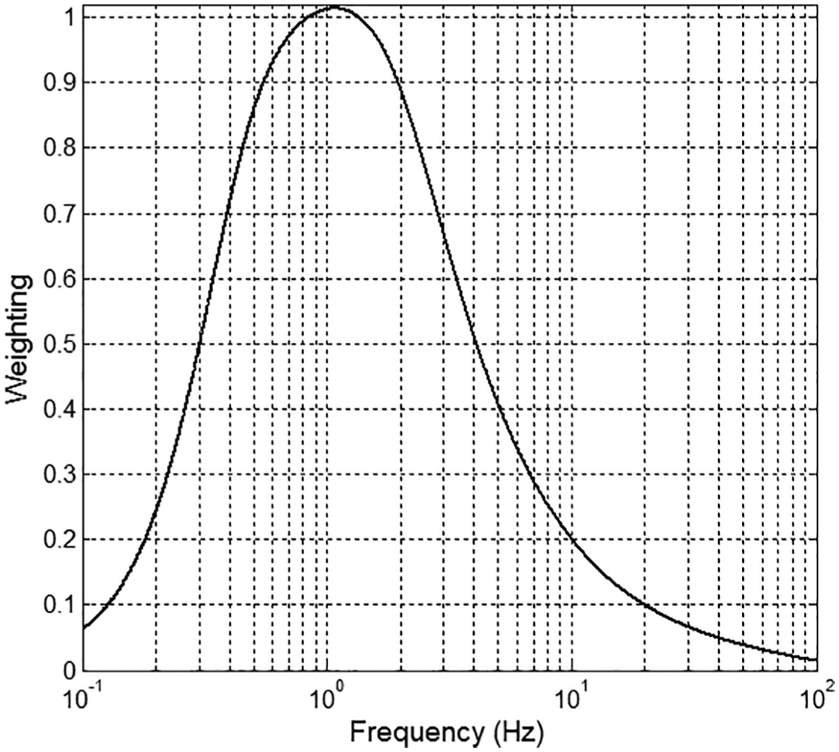
Lateral ride comfort weight function according to ISO 2631 and KS R 9216.
Figure 2 shows that measured acceleration data have a maximum at around 1 Hz in Korean commercial railway vehicles. It also implies that the dominant frequency range is 0.4–6 Hz, and the control bandwidth, 0.2–10 Hz, is enough to achieve desired ALS performance.
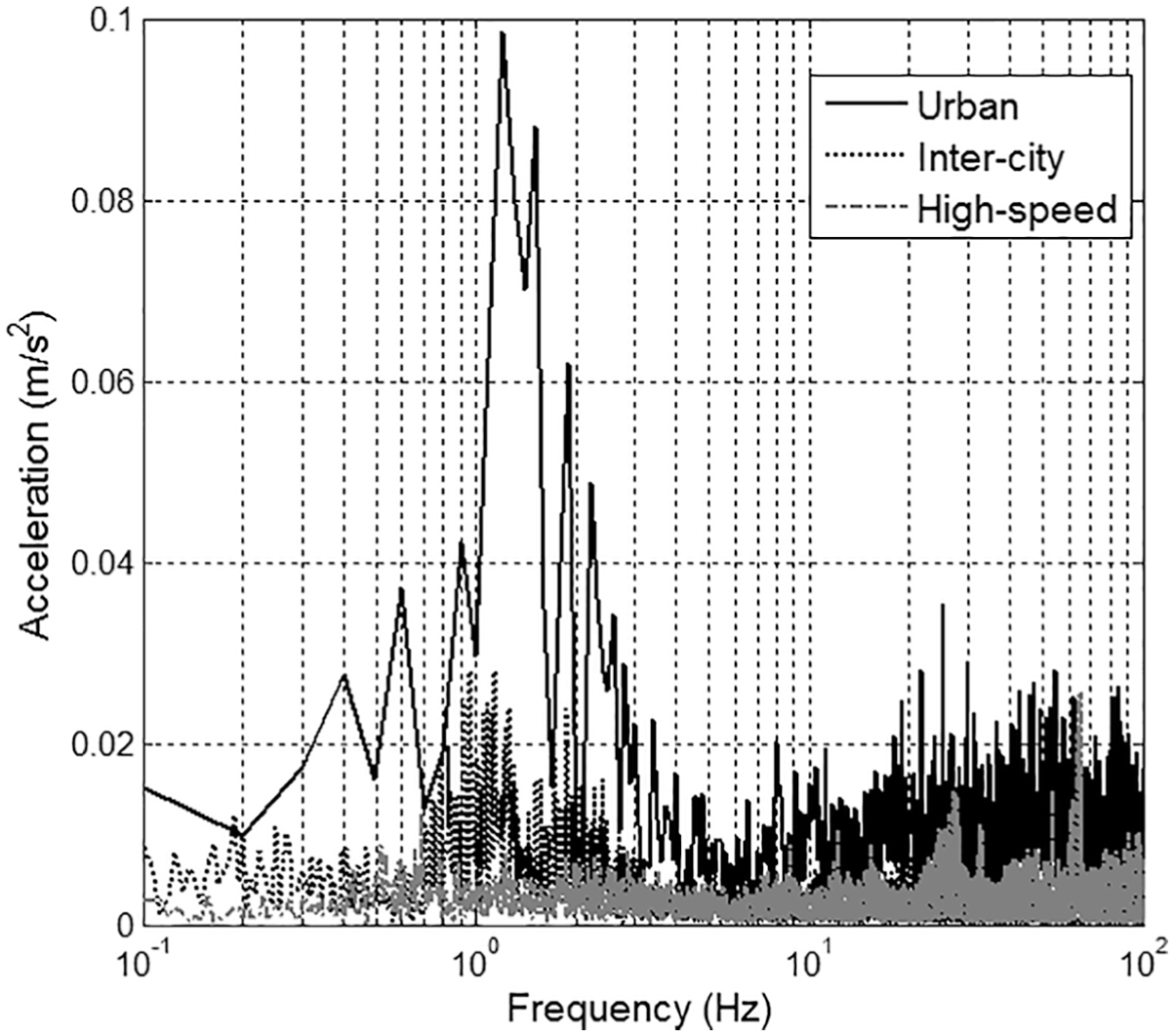
Carbody lateral accelerations in Korea of commercial railway vehicles measured on the floor above each front bogie.
Selection of actuator type
Application of several actuator types has been attempted for the active mechanisms of railway vehicles. Among them, electromechanical, electromagnetic, hydraulic, and pneumatic actuators are considered most practical. Each type has its own advantages and disadvantages. Therefore, the choice of actuator is dependent on the desired performance and application range of ALS.
Most electromechanical actuators in railway vehicles are composed of an electrical motor and a screw mechanism converting rotation to translation. An ALS using an electromechanical actuator was developed by Alstom for high-speed railway vehicles. 10 Braghin et al. 11 developed an active yaw damper using an electromechanical actuator to improve running stability and curving performance. The performance of both actuators was investigated during on-track tests but they have not yet been commercialized.
The force per volume of electromechanical actuators can be designed to be higher than that of electromagnetic actuators at the same power density, by adjusting the transfer ratio between rotation and translation of the screw mechanism. This can be the main advantage of electromechanical actuators, although frequency response is slower as force density increases. The drawback of electromechanical actuators is their increased need for maintenance due to the additional mechanical components.
Electromagnetic actuators are often preferred since they are able to have large frequency bandwidth and to minimize the number of other components. A permanent-magnet-type linear synchronous motor was developed to replace a pneumatic actuator for controlling lateral vibration of railway vehicles in Japan.12,13 It was reported that the ride quality was improved more than 10 dB at the 10-Hz frequency bandwidth under roller rig testing, and the ALS was installed to Fastech 360 for on-track testing. However, on-track test results have not yet been made available.
The general limitation of electromagnetic actuators concerns the difficulty in reducing their size and weight while maintaining their original performance due to the electromagnetic force generating principle. It is known that the electromagnetic force is proportional to the volume of the electromagnetic system. Hence, required performance specifications should be carefully calculated when considering the location to install the ALS.
Hydraulic actuators have faster response time compared to electromechanical actuators and have larger force capacity than electromagnetic actuators. Therefore, they were often chosen for railway applications with pneumatic actuators in the early phase of ALS. Shimamune and Tanifuji 14 carried out an experimental analysis of hydraulic actuators for active suspension of railway vehicles. They reported that hydraulic actuators could control up to 10-Hz frequency range. The major disadvantage is the risk of oil leakage and the use of another power source instead of the existing power sources of conventional railway vehicles, such as electricity or air.
The advantage of pneumatic actuators is that they can use the already existing pneumatic components of railway vehicles, and their cost is relatively cheap. In contrast, due to the large air compressibility, they have high nonlinearity and their controllable bandwidth is lower than other actuators. Still, their advantages were attractive to railway vehicle engineers and the world’s first operational full ALS, developed by Japan, uses pneumatic actuators. 12
In recent practical approaches to railway vehicle engineering, effectiveness and reliability have been recognized as more important than the nominal price because they can reduce maintenance costs and consequently prove more affordable during the life cycle. From this perspective, electromechanical and electromagnetic actuators are better than hydraulic and pneumatic actuators. Also, considering the target control bandwidth of section “Determination of ALS Control Bandwidth,” electromagnetic actuators are better than electromechanical actuators. However, as mentioned above, due to the limitations of size and weight, target performance and installation place should be carefully investigated. This process will be introduced in the following section.
Control algorithm
Control algorithms for ALS have been extensively studied for several decades. Among them, the most implemented algorithm is skyhook damping. 12 The passive damper in the conventional railway vehicle reduces the vibration energy proportionally to the relative velocity between the carbody and bogie. With skyhook damping, the relative velocity between the carbody and the sky, namely, the absolute velocity of the carbody, is damped. Therefore, it is very effective in isolating the carbody vibration caused by track irregularities transmitted through the bogie. 15 However, it can create large deflection of the secondary suspension or require large control power that exceeds the actuator’s capacity in curves.16–18
H∞ control is known as the advanced control methodology to acquire good performance, stability, and robustness. It was applied to control the world’s first operational full ALS in Japan. 12 But the controller design of H∞ is a high-order number model compared to skyhook control since the order number of the weight function is included. Thus, model reduction and weight function tuning are important, but rather sophisticated for industrial implementation. Moreover, Orvnäs et al. 19 reported that there is no large difference between skyhook damping and H∞ control on straight track and in the circular curve section. Their results show that the advantage of H∞ control is the ability to reduce the relative displacement between the carbody and bogie with HOD in transition curves. Therefore, skyhook damping with proper high-pass filter can be better applied to ALS of railway vehicles in the practical approach because its principle is simple and easy for field engineers to understand.
The most general control law for active suspension systems is the so-called skyhook control law. 20 Many studies have been undertaken in connection with the skyhook control of (semi)active suspensions for railroad and road vehicles.21,22 Li and Goodall 23 reported that it has been examined theoretically a number of linear approaches for applying absolute velocity or skyhook damping and compares different control strategies for applying skyhook damping control laws in active suspension systems for railway vehicles. Also, the skyhook control was addressed at the previous research. In the previous study, the skyhook control with magnetorheological (MR) damper on the secondary suspension in railway vehicle was conducted using 1/5-scaled railway vehicle and roller rig.16,17
Installation place of actuator and sensor
In the previous section, regarding control bandwidth and reliability, an electromagnetic actuator is suggested to be a better choice for ALS; however, its size is generally a bit large to be installed in the narrow space between a conventional carbody and bogie. As for other places, the actuator can be mounted under the bogie frame and connected to the carbody through the center pivot. Figure 3 shows the simplified model of a railway vehicle to investigate the influence of the vertical position of ALS actuator and sensor. The real vehicle model includes frequencies and modes which are not taken into account in the design of ALS. Therefore, the simplified model is more appropriate insofar as it can express the control target modes well. In the simplified model, the non-linear effects (friction, non-linear spring stiffness, and non-linear damping coefficient of the damper) are neglected. Wheel-axle-set mass and creep forces between wheel and rail are also neglected. Finally, the simplified model includes one rigid bogie and a half carbody but not the actuator dynamic model. From Figure 3, the state space equation can be expressed as Equations (3)–(5)

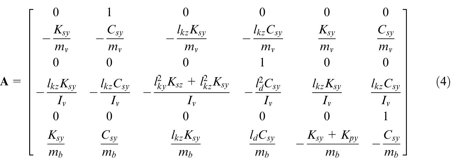
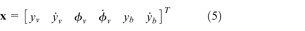
where
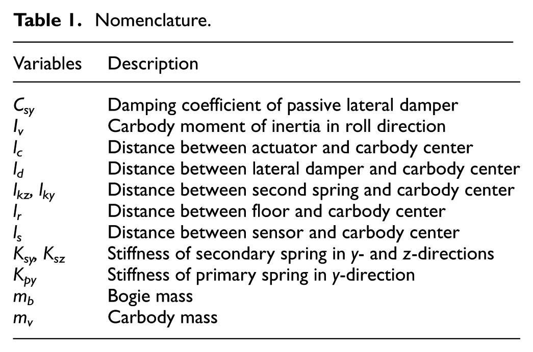
Nomenclature.
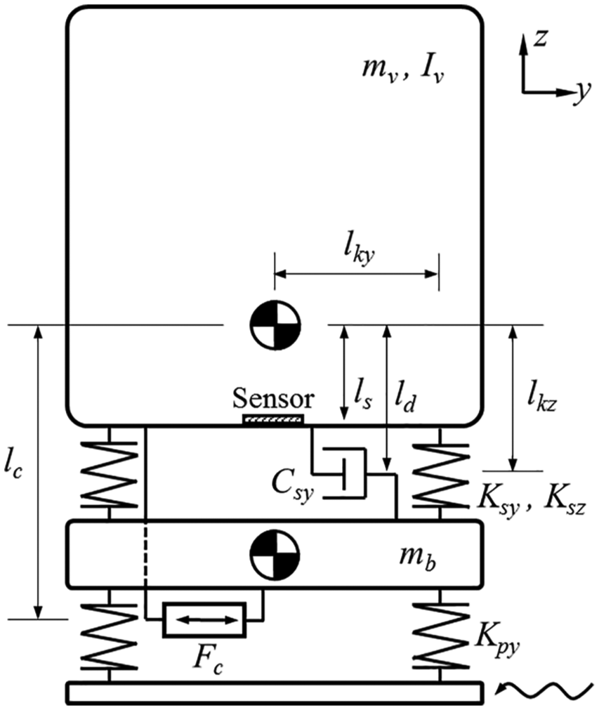
Simplified model of a railway vehicle to determine the vertical position of the actuator.
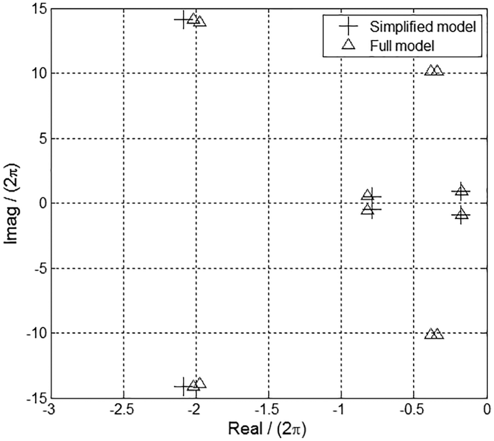
Comparison of eigenvalues between the simplified model and full model.
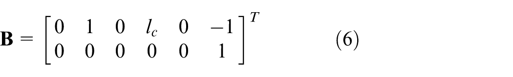
In the closed-loop system with skyhook control, input and control gain vectors can be expressed as Equations (6) and (7)
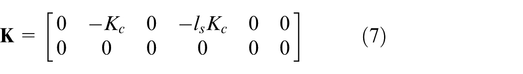

where
According to the evaluation guidelines of ride quality, the lateral acceleration should be measured on the floor of the cabin to use the weight function of Figure 1. In this case, the measured acceleration includes the roll component as well as the pure lateral acceleration. Therefore, output vector,

where lr is the relative distance between the carbody roll center and floor. From Equations (3)–(9), the closed-loop system with skyhook controller can be expressed as Equations (10) and (11)


Figure 5 shows the lateral frequency response of the closed-loop system model. Here, passive lateral damping coefficient, Csy, is assumed to be zero, Kc is 4 × 10⁴; ls has the same value as lc; and the amplitude of disturbance, ν, is 5 × 10⁻³. Reduction performance of the ALS under the bogie is slightly lower than the ALS between the carbody and bogie in the 0.6–1 Hz range. However, reduction performances of the two models at peak frequency are very similar, about 10 dB.
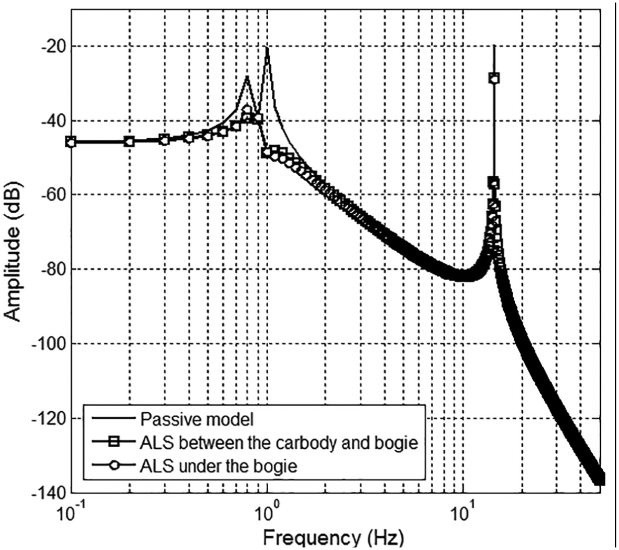
Frequency response of the ALS carbody on the floor in lateral direction.
The influence of the ALS on the roll movement of the carbody is displayed in Figure 6. The roll movement is increased at frequencies below 0.7 Hz, but resonance peak around 1 Hz is reduced. Therefore, gain tuning should be performed carefully in order not to excessively excite the roll movement at low frequency. Despite the increased roll amplitudes at the low-frequency range, those results are acceptable because roll vibration can also be significantly reduced at the dominant frequency. The response of the ALS under the bogie is a bit larger compared to the response of the ALS between the two bodies, but the difference is small.
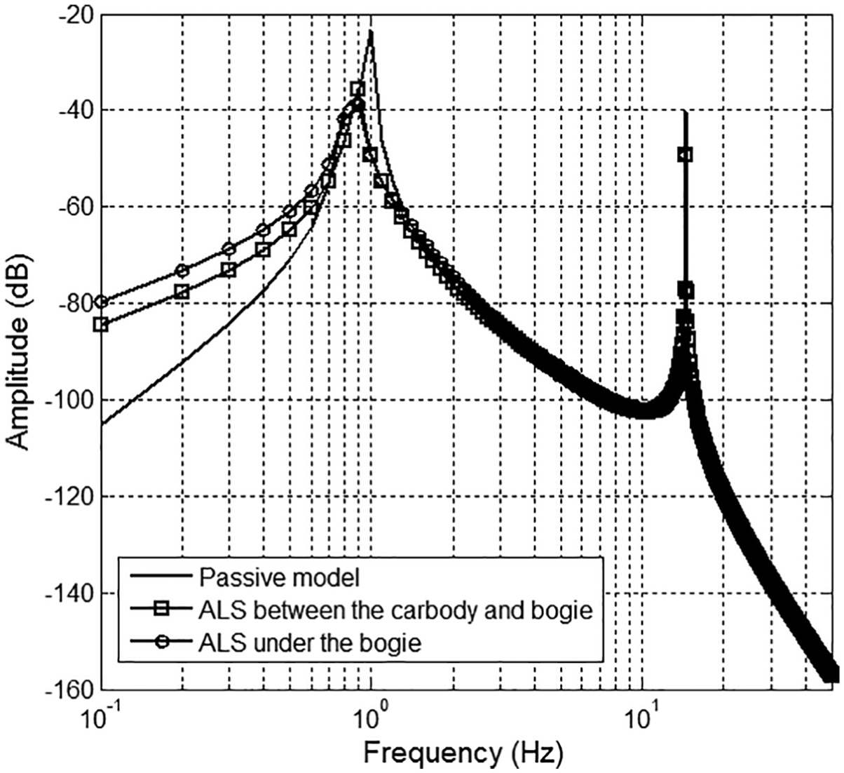
Frequency response of the ALS carbody at the roll center in roll direction.
Figure 7 shows the frequency response of the ALS carbody according to the position of the sensor for skyhook control when the actuator is installed under the bogie. The effect of the sensor position changes around 1 Hz. At the peak frequency, better performance can be acquired when the control sensor is positioned on the floor. It appears explicitly in high control gain. This result can be explained from the co-location problem between the two positions of the control sensor and measuring point for ride quality evaluation as shown in Figure 8. When the control sensor is located on the actuator, the performance of the ALS might be underestimated in the process of ride quality evaluation, since the skyhook controller exerts its force to reduce vibration measured on the actuator, not on the floor. However, it can improve maintenance efficiency to install the control sensor and actuator in the same position. Therefore, the position of the control sensor is a trade-off of the ALS design.
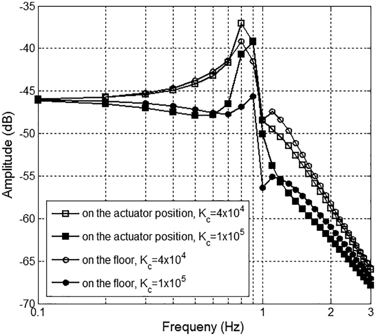
Frequency response of the ALS carbody on the floor in lateral direction according to the position of control sensor.
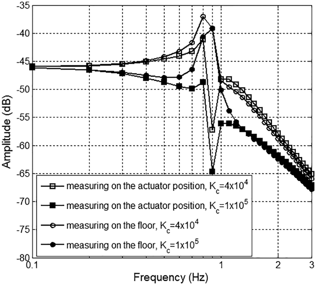
Frequency response of the ALS carbody in lateral direction according to measuring position when the control sensor is positioned on the actuator.
Fail-safe strategy
The concern about fail-safe is one of the significant reasons that implementation of active systems in railway vehicles is difficult. Particularly, railway vehicles should be able to travel while maintaining their minimal stability and safety even if the ALS reaches a fault condition. Therefore, in this study, the fail-safe strategy focused on how to sustain the performance of the conventional railway vehicle when the ALS is logically turned off by diagnostic algorithm or physically turned off.
In the first step of the fail-safe strategy, the control mode is activated by comparing two signals, such as vehicle speed and temperature inside the actuator, with each limit value. When the vehicle speed is lower than the limit value, the control mode is deactivated to reduce energy consumption and to prevent the malfunction of an actuator overturning the vehicle in a high cant curve. The actuator temperature has two limit values: yellow and red. The control mode is activated when the temperature is lower than the red limit, but control effort is partially restricted between the two limit temperatures.
In the next step, to avoid the excessive motion of the actuator caused by sensor fault, an additional sensor is attached and the output signals of the two sensors are compared to check the sensor fault as shown in Figure 9. If one of the two sensors has trouble, the RMS value of the difference between the two signals for N samples becomes larger than the limit reference, Sd. Then, the sensor fault signal, Sf, is converted into true and control mode is deactivated. The signal which has the minimum absolute value between the two sensors is selected for control loop. This procedure can help reduce the risk of excessive motion created by the sensor fault, during the calculation process of N-sampled RMS, before the sensor fault signal turns true. Figure 10 shows the overall control and fail-safe scheme of the ALS system.
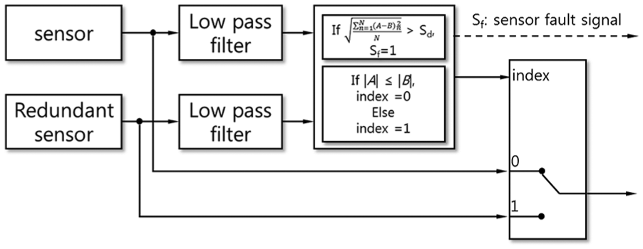
Fail-safe diagram of control sensor.
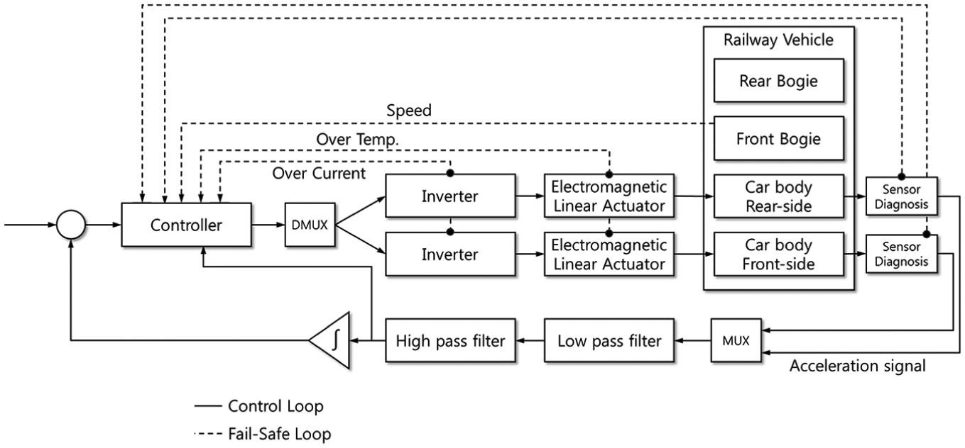
Control and fail-safe scheme of the active lateral suspension system.
For the final fail-safe strategy, conventional hydraulic lateral dampers can be considered for installation in parallel with the ALS system because the lateral damper has some effects on the running stability of the railway vehicle. 24 Figure 11 shows the distribution of the measured velocity of lateral damper stroke when Korean railway vehicles travel their commercial lines. The most frequent velocity is about 0.01 m/s and most of the velocity is distributed in the range of 0.05 m/s. The damping forces at 0.05 m/s are about 1.5 kN for inter-city trains and about 2 kN for high-speed trains. Hence, the ALS can overcome the interference of the passive damper in most sections except sharp curves.
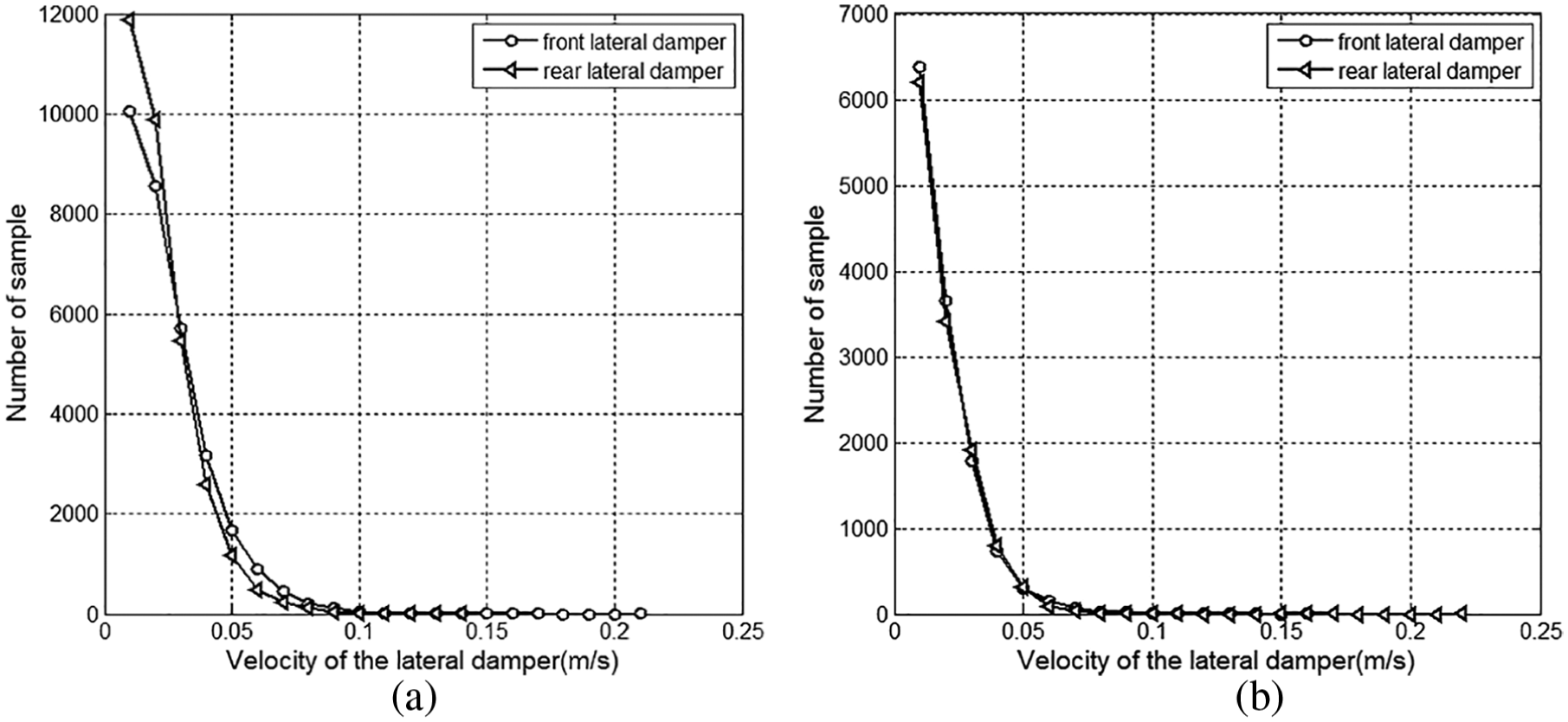
Stroke–velocity distribution of hydraulic lateral dampers of Korean railway vehicles when they travel their commercial lines: (a) inter-city train and (b) high-speed train.
Simulation
The full-scale vehicle model to estimate the performance of the ALS is built up in the railway vehicle dynamic simulation tool VI-Rail as shown in Figure 12. It consists of a rigid carbody connected to two bogies through the secondary suspension. The secondary suspension consists of two air springs, two vertical dampers, and one passive lateral damper. The actuators are placed diagonally to the passive lateral dampers under each bogie frame and connected to the carbody through the center pivots. All parameters of the full-scale vehicle model are set up according to a commercial inter-city train of Korea, but the dynamic characteristics of the actuator are neglected. The signal filters in the control loop of Figure 10 are considered in the simulation but the fail-safe loops are neglected.
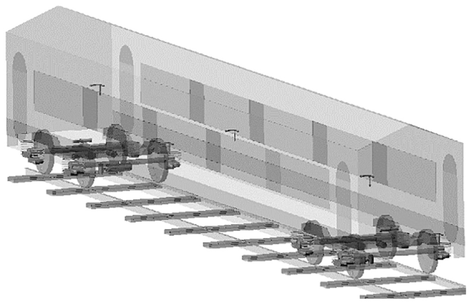
Full-scale vehicle model for simulation in VI-Rail.
The simulations were performed on straight track at a vehicle speed of 100 km/h with offered track irregularities by VI-Rail. Ride quality was evaluated according to KS R 9216 as a post-process using the simulation results. Figures 13 and 14 indicate that lateral acceleration was effectively reduced by the ALS. From KS R 9216, the ride quality was evaluated as 103.1 dB for the conventional passive vehicle and 94.6 dB for the ALS vehicle. As predicted in section “Design of the ALS system,” roll acceleration of the ALS vehicle at the low-frequency range was increased. This implies that the simplified model is well designed and sufficient for use in the preliminary design process. Control forces of each actuator are shown in Figure 15. Maximum forces were about 5500 N at both actuators. RMS values were 1500 and 1491 N, respectively. Maximum stroke of actuator was analyzed as 0.019 m at the front bogie actuator. However, allowable stroke of the actuator should be designed to be larger than the distance of bump stop in order to protect the actuator in sharp curves.
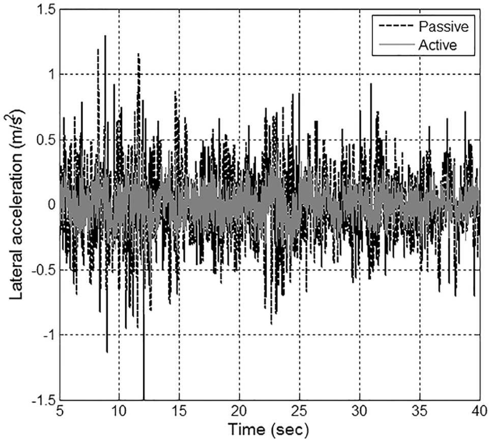
Carbody lateral acceleration on the floor.
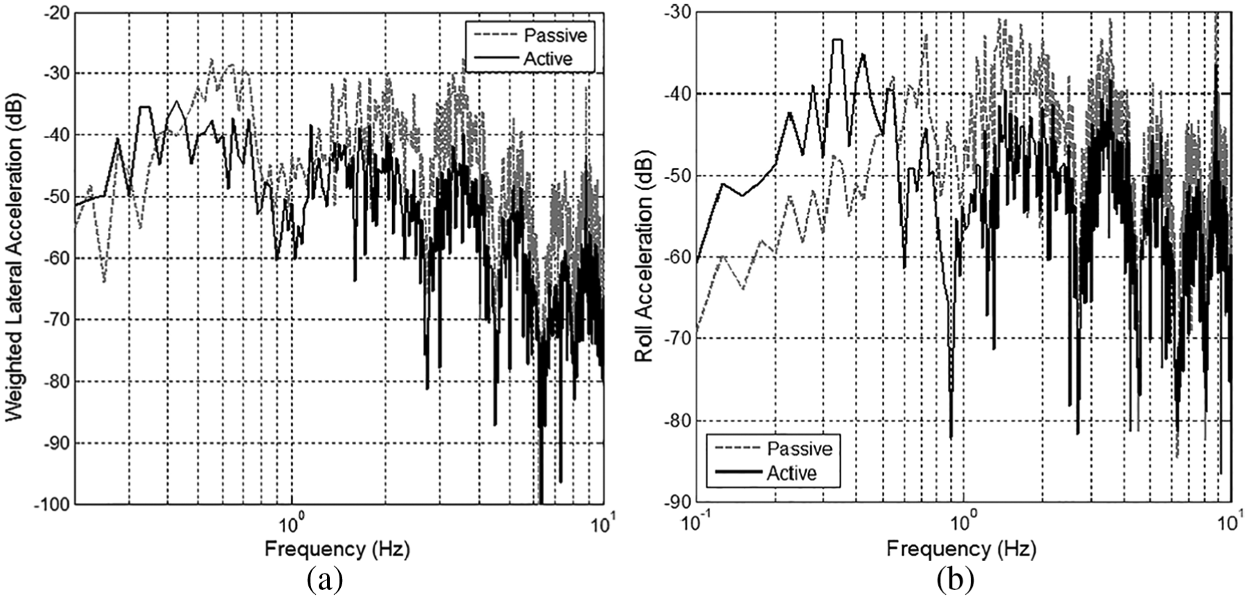
FFT results of carbody acceleration: (a) lateral, filtered by the ride quality weight function and (b) roll.
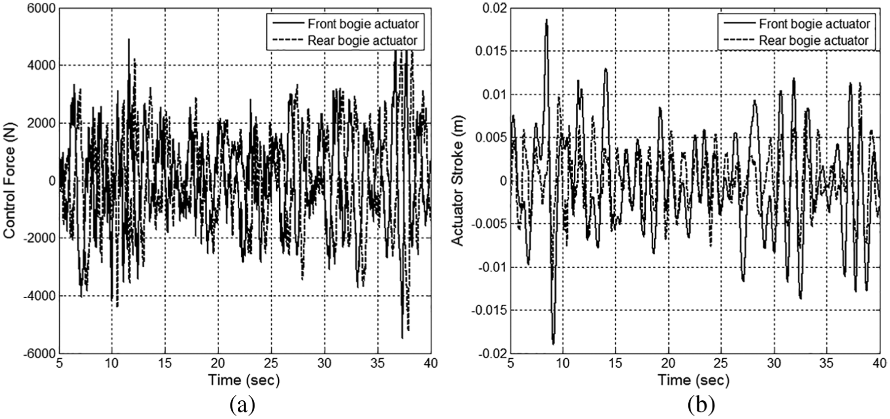
Motion of actuators: (a) control force and (b) stroke.
Full-scale vehicle tests
Prototype of ALS for full-scale vehicle
In the previous section, it was estimated that ALS can enhance the ride quality to be more than 10 dB at the peak frequency and about 8 dB on average. This performance is about two times higher than the target performance described in section “Determination of ALS Control Bandwidth,” even though the actuator characteristics were neglected during the simulation. Therefore, in the prototype design of electromagnetic actuator, the force-generating performance was decreased compared to the simulation control force shown in Figure 15, but the size and weight of the actuator can be reduced instead.
Figure 16 shows the prototypes of the tubular-type electromagnetic actuators and control sensor blocks. The diameter and length of the actuator are 0.2 and 0.5 m, respectively. Maximum stroke is ±0.05 m. Rated force is 1200 N and maximum force is about 3000 N. In comparison with simulation, the prototype actuator is designed to have 80% of RMS and 50% of maximum values. Three thermocouples are embedded inside the actuator to measure the internal temperature. Maximum temperature among the three points is used for the fail-safe loop. An acceleration sensor and a redundant acceleration sensor are packed together in an aluminum block to protect them from dust, water, and so on. Different types and manufacturers are selected for the two sensors. Figure 17 shows the frequency response of the prototype actuator. Output force is measured along the frequency of applied force command. This test is a reasonable method to verify its performance because the linear electromagnetic actuator itself is a kind of non-spring mass system and the skyhook control is only concerned about absolute velocity damping force. The prototype actuator has a little phase delay within the control frequency range due to mass of mover and inductance of coils, but it is small enough to be negligible. To carry out the proposed control and fail-safe loop in the full-scale vehicle tests, a commercial DSP board, dSPACE 1103, is used.
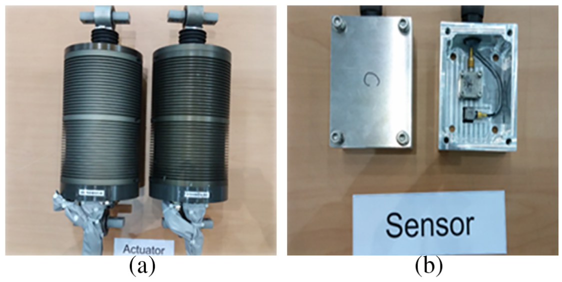
Prototype of ALS: (a) electro-magnetic actuators and (b) sensor blocks.
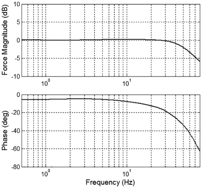
Frequency response of the actuator prototype: measured force along the frequency of applied force command.
Roller rig tests
The prototype ALS was applied to an urban railway vehicle and an inter-city railway vehicle for roller rig testing. Figure 18 shows the experiment setup for each vehicle on roller rig. Test speeds were determined to be their typical commercial speeds, 70 km/h and 100 km, respectively, and measured track irregularities of their commercial lines were used to excite the vehicles. Four linear variable differential transformers (LVDTs) and four accelerometers measured the bogie displacement and acceleration for observing the stability and safety during the tests.
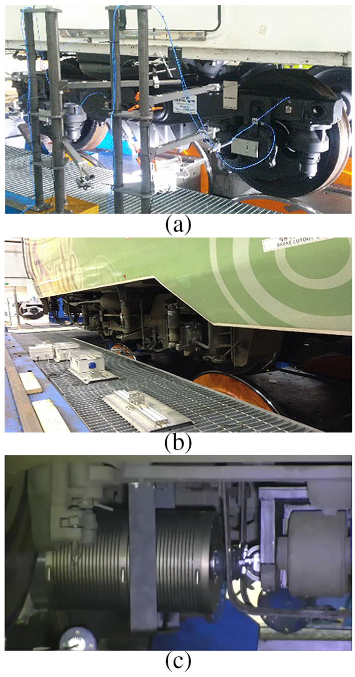
Experiment setup for the ALS vehicles on roller rig: (a) urban railway vehicle, (b) inter-city railway vehicle, and (c) actuator prototype installed under the inter-city vehicle bogie.
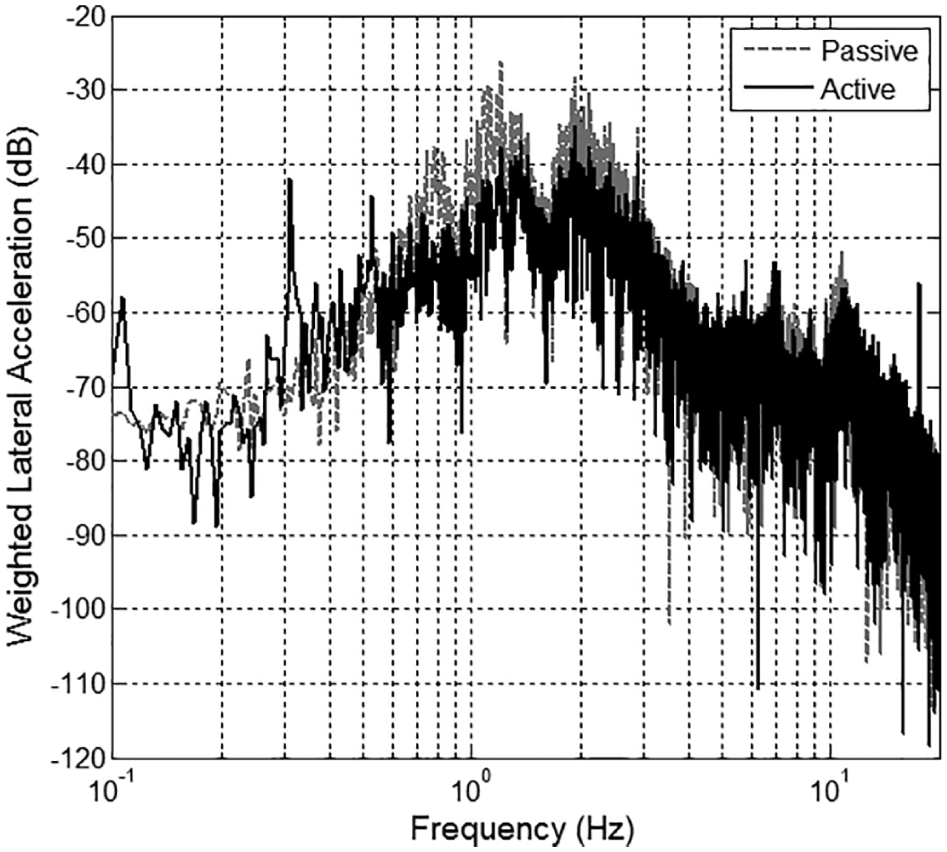
Figures 19 and 20 show good performance of the ALS in the urban railway vehicle. Lateral acceleration was reduced to about 12 dB at the peak frequency. From KS R 9216, ride quality was 103.7 dB for the passive vehicle and 96.9 dB for the ALS vehicle. Therefore, the proposed ALS enhanced the lateral ride quality by 6.8 dB in the urban railway vehicle. The inter-city vehicle had similar results as shown in Figure 21. Peak acceleration was reduced from −26.19 to −38.75 dB when the ALS was activated, and the ride quality according to KS R 9216 was enhanced from 102.8 to 95.7 dB. From the roller rig test results, it can be estimated that the prototype ALS is well designed and performs sufficiently to achieve the desired target.
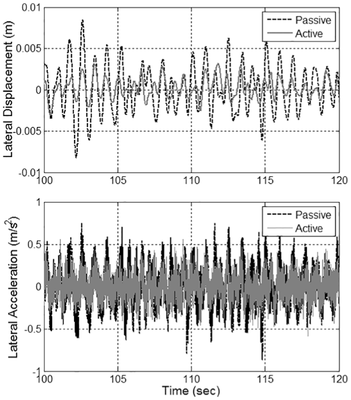
Lateral motion of the urban vehicle carbody: (a) displacement and (b) acceleration.
FFT results of lateral acceleration of the urban vehicle carbody, filtered by the ride quality weight function.
FFT results of lateral acceleration of the inter-city vehicle carbody, filtered by the ride quality weight function.
Field tests
Field tests with the inter-city train were performed over 8 days on a 6-km test track. The total test distance was 1192 km, and the typical test speed was 90–100 km/h. The test train was composed of five vehicles: a power car, a generator car, and three passenger cars. The ALS was applied in the middle of the passenger cars as shown in Figure 22.
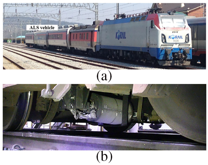
Test train: (a) overview and (b) installed actuator in the ALS vehicle.
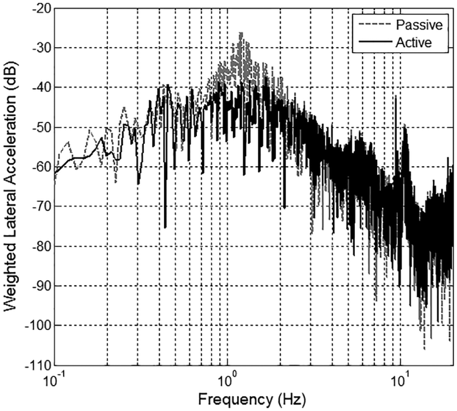
Figure 23 displays one of the field test results. The ALS prototype performed well, as expected from the simulation and roller rig test. Maximum control forces of both actuators were about 3000 N because restriction of control command was added in the fail-safe loop to protect the actuators, separately from overcurrent detection. RMS forces were 1121 and 1282 N, respectively, acceptable to the actuators considering their designed rated force. Figure 24 indicates that the passive and ALS passenger vehicles have −22.6 and −34.9 dB at the peak frequency, respectively. Each ride quality was estimated to be 103.3 and 96.6 dB. Among the simulation, roller rig test, and field tests, there are good agreements for reduction rates at the peak frequency but the simulation result was better than the roller rig and field test results in the case of ride quality, since the performance of the actuator is reduced in real implementation.
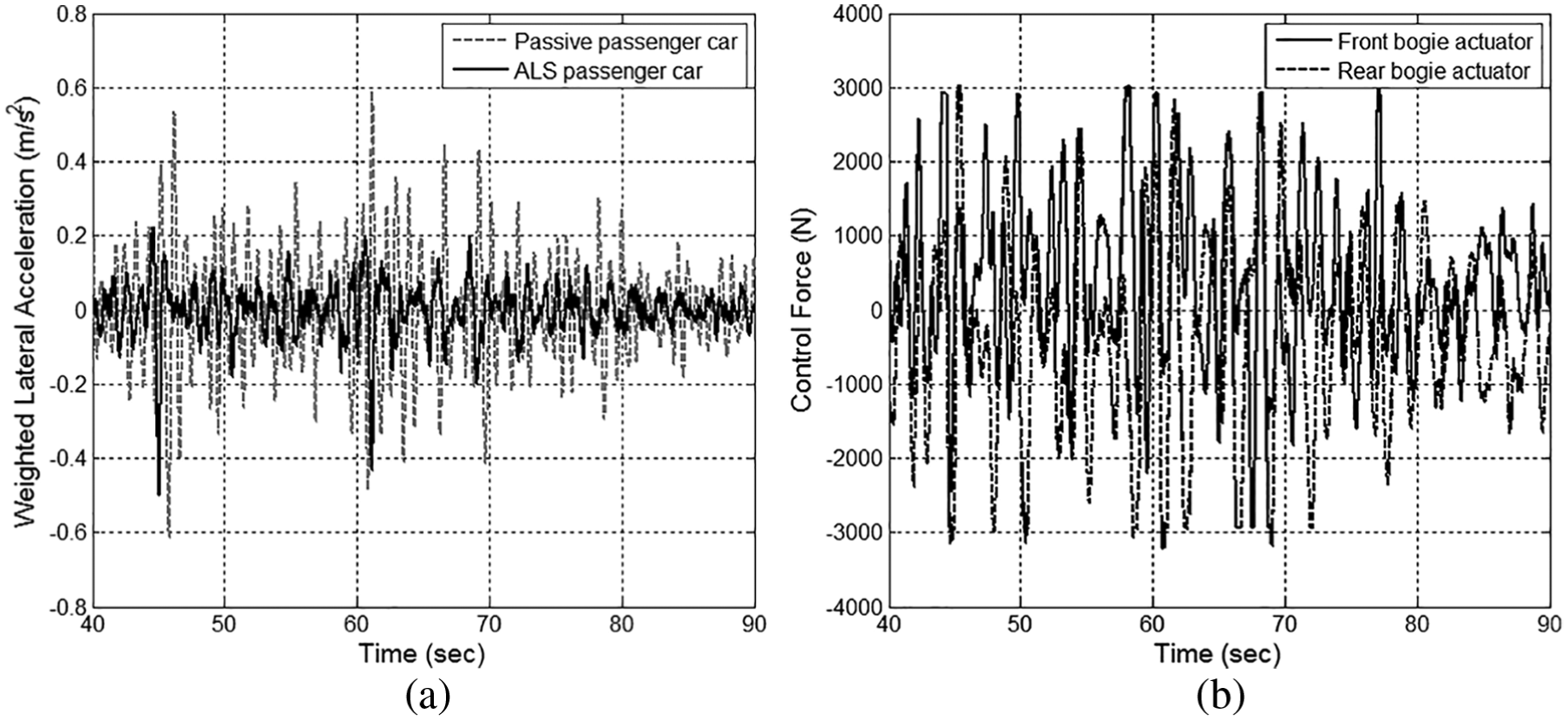
Field test results: (a) lateral acceleration filtered by the ride quality weight function and (b) control force.
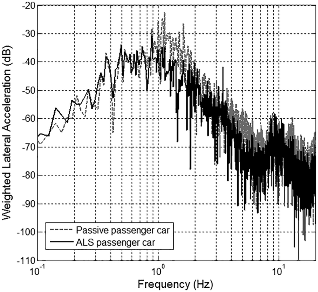
FFT results of carbody lateral acceleration, filtered by the ride quality weight function.
Several verifications of the fail-safe loop were performed in the field tests. As shown in Figure 25, ALS control was deactivated at 50–80 s while the train speed was lower than the speed limit. The actuator temperature was artificially boosted while the control was in activation. The control signal was restricted within 60% of control command in the yellow-limit section and deactivated in the red-limit section. It was re-activated after the temperature returned to normal condition.
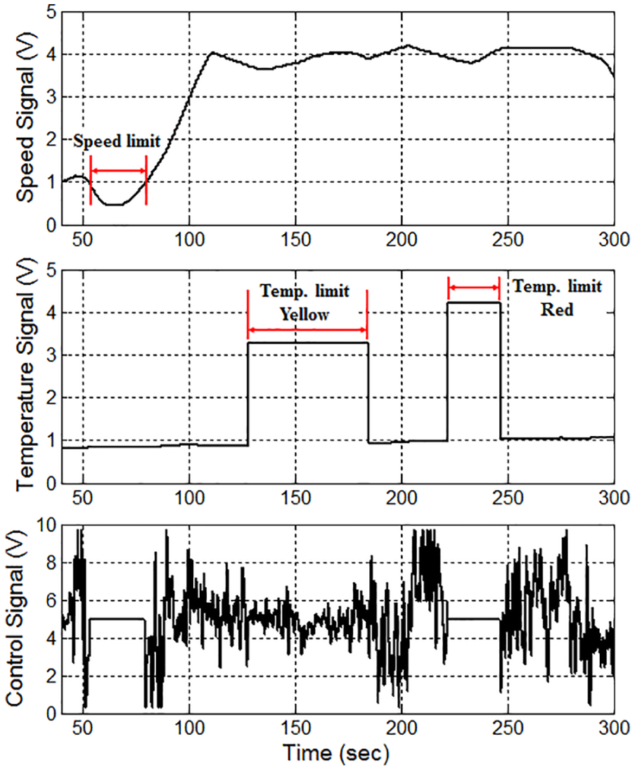
Fail-safe loop tests for train speed and actuator temperature.
To validate the fail-safe of the control sensor, an accelerometer in the sensor block (Figure 16(b)) was slightly inclined to add gravitational acceleration. However, the sensor fail-safe algorithm (Figure 9) gives the normal acceleration signal as shown in Figure 26. During the test, ALS control was normal, since difference in RMS value between the two sensor signals did not reach the fault condition. A sensor fault would be triggered when the accelerometer inclined for a longer period of time or with a larger magnitude.
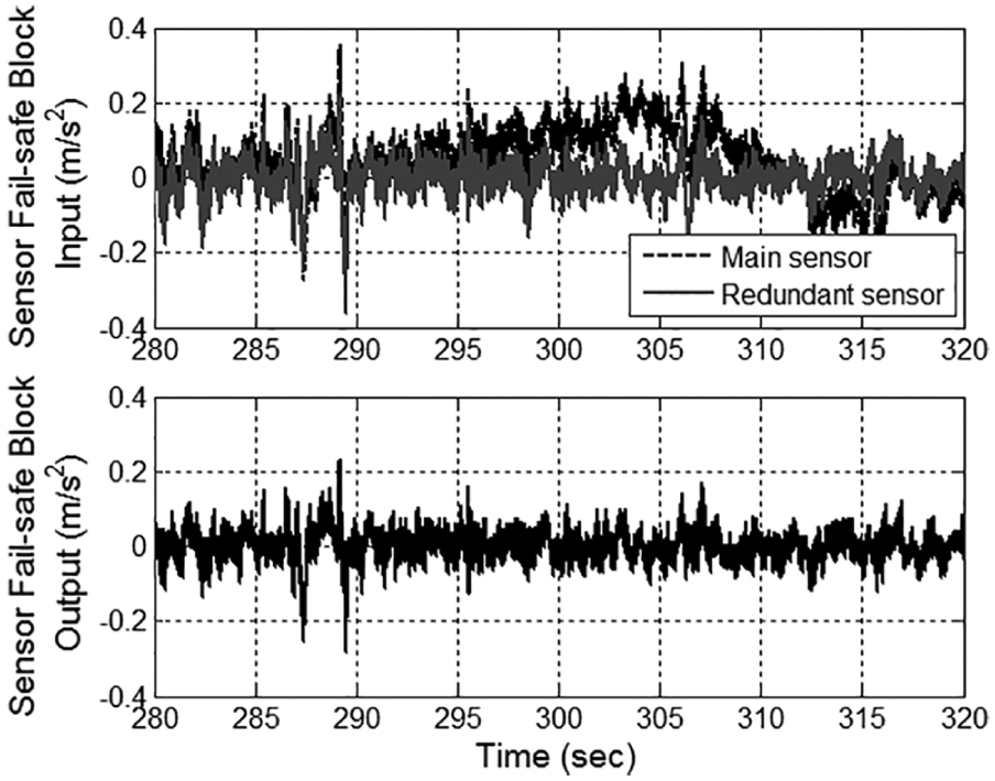
Fail-safe test for control sensor with a redundant sensor.
Conclusion
ALS technologies have been well developed for several decades but they have not been widely used in service operation due to relatively high costs for implementation and maintenance and concerns about fail-safe. Therefore, this paper suggests a more practical approach for the ALS system. This objective can be achieved through proper compromise among desired performance, cost, and maintenance. The control performance target is determined from the vibration energy that the ALS has to absorb along the weight function for ride quality evaluation, and the actuator type is selected to achieve the control target performance. The skyhook control algorithm was chosen for its practical implementation because it also has good performance in the proposed control target bandwidth, compared with other sophisticated control algorithms, like H∞, and it is easy for field engineers to understand in the maintenance process. It is one of the important factors for a practical approach.
The available installation position of actuator and sensor was investigated using the simplified railway vehicle model. The investigation found that the actuator is best installed under the bogie, even though the control performance is slightly decreased, because in this position, the ALS can be applied to existing conventional bogies with only minor changes to their original design, and it can reduce the time that it takes for field engineers to check the actuator or to uninstall and re-install the actuator for maintenance. The sensor position is a trade-off between control performance and ease of maintenance. The ALS can be installed under the bogie as a module composed of the actuator and the sensor when the sensor position is decided to be near the actuator. However, the control performance at the peak frequency will be decreased compared to the floor position. The underframe of the carbody can be an alternative position. The control performance is similar to the floor position and field engineers can approach the sensor block more easily compared to the floor.
The rated force of actuators for full-scale vehicle test is designed considering the simulation results using VI-Rail. Maximum allowable force is decreased, in order to reduce the size and weight of the actuator, to be half of the simulation results.
Through the roller rig and field tests, the performance of the proposed ALS was validated. Lateral ride quality was improved 7.1 and 6.7 dB in the roller rig test and field test, respectively. The fail-safe strategy was also verified during the field test. These results show that the proposed ALS is designed appropriately and can be used in practical implementation.
Footnotes
Declaration of conflicting interests
The author(s) declared no potential conflicts of interest with respect to the research, authorship, and/or publication of this article.
Funding
This work was supported by a grant from the R&D Program of the Korea Railroad Research Institute (PK1801B), Republic of Korea.