
Abstract
Background:
Mast is mainly used for assisting the communication-vehicle-mounted optical transceiver to obtain a coarse tracking of objects rapidly and accurately, especially when objects are communicating among different regions.
Methods:
This study first conducts a force analysis of a vehicle-mounted mast specialized for laser communication and then derives dynamic characteristics of the mast under wind load. In order to validate tracking precision and the stabilization of the optical transceiver, and examine the wind disturbance resistance of the mast, a series of field experiments were carried out.
Results and Conclusion:
Finally, the test errors were analyzed in detail, and the experimental results demonstrated that the tracking error of the vehicle-mounted optical transceiver is less than 80μrad which means the optical transceiver satisfies the system requirements in terms of precision. Furthermore, both theoretical analysis and experimental results revealed that designed mast satisfies the technical requirements of the vehicle-mounted laser communication, thus the feasibility of the mast in vehicle-mounted communication was validated.
Keywords
Introduction
Considering that the information is transmitted between two or multiple operation platforms, the communication stations should be visible in laser communication on the ground.1,2 In a complex terrain, ground vegetation and buildings are ubiquitous, which inevitably affects the communication between stations. 3 Therefore, the optical transceiver supports should be set up high on the mast to overcome the blockage by the vegetation and buildings so as to ensure the intervisibility and good communication. Recently, Harikrishna et.al. 4 conducted full-scale experiments on a 50-m tall guyed mast to obtain the dynamic response in ambient wind conditions. Ho et al. 5 studied the vibration of guyed masts under wind load with the discrete random vibration method. However, none of those studies considered the payload on the mast. As a special vehicle-mounted optoelectronic system, the vehicle-mounted mast electro-optical communication system is characterized by extremely flexible mobility. In particular, the vehicle-mounted mast for the electro-optical communication system is mainly used for spying, ranging and location of the objects in ground-to-ground communication, which is especially applicable to the dynamic environment.6–8 Since the optical transceiver is generally set up on the mast, both structure and rigidness of the mast will directly affect the tracking precision of optical transceiver. Therefore, the design of vehicle-mounted mast is also very important for ensuring the normal communication between optical transceivers.
Mast design
Mast structure
The structure of the optical transceiver and transmission process of the vehicle-mounted optical transceiver are presented in Figure 1.
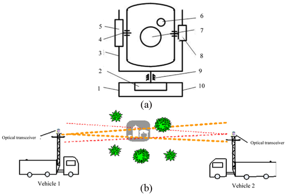
The vehicle-mounted laser communication system: (a) sketch of the optical transceiver and (b) transmission process of the vehicle-mounted optical transceiver.
As shown in Figure 1(a), optical transceiver mainly included the azimuth and the pitch frame structure. The two frame axis is designed as the stability axis with the angular position sensor. 9 The vehicle-mounted mast and optical transceiver we used in this study were as follows: the designed mast was placed on the communication vehicle, the mast height was 12 m and the vehicle height was 4 m. Both tracking precision and stabilization precision of the optical transceiver were equal to 1σ. In order to achieve a convenient installation with a firm fixing and light load, the triangular structure was adopted for the mast. Indeed, the mast was made up of 45# steel by welding, and the surrounding steel tubes were connected with the main steel tube in a herringbone pattern. Besides, the springs were arranged in a row on the axis, and their interactions were in the opposite direction to the gravity of the mast and load. Also, the springs were fastened to the vehicle on one side and vertically attached to the axial direction of the mast on the other side. Accordingly, when the mast rotated around the axis, the torsional springs imposed a reactive force to reach the moment equilibrium and reduce the dragging force. Correspondingly, the sketch and work process of the vehicle-based mast is showed in Figure 2.
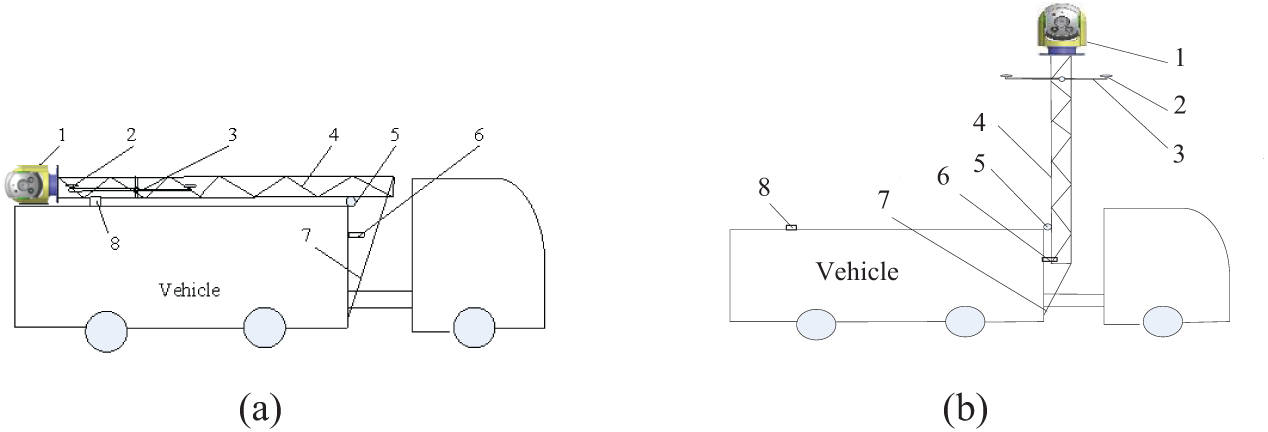
Simplified mast structure: (a) non-operating state and (b) operating state.
As shown in Figure 2(a), for the non-operating state, mast is generally laid and fixed on the engineering vehicle via the rotating axis and fastening device. In the preparation stage, the steel wire ropes are usually pulled by the rotating winch which is driven by a motor or a human, and the mast is rotated around the rotating axis. After reaching the operating position, the mast remains fixed vertical to the locking device, as showed in the Figure 2(b).
Modal analysis
In fact, nearly all the large-inertia power systems will face with the problem of structural resonance. In this case, the structure resonance of the mast is mainly caused by its flexibility and high-load inertia. The stability of the mast will be threatened if the resonant frequency is close to the frequency of the servo system, since every mast has a certain resonant frequency. Therefore, the inherent frequency of the mast mechanical part is generally set to be 5–8 times greater than that of the drive part. In addition, it is also necessary to perform the modal analysis on the mast to ensure the distribution of the frequency. The modal analysis results for the first six orders for the mast we used are shown in Figure 3.
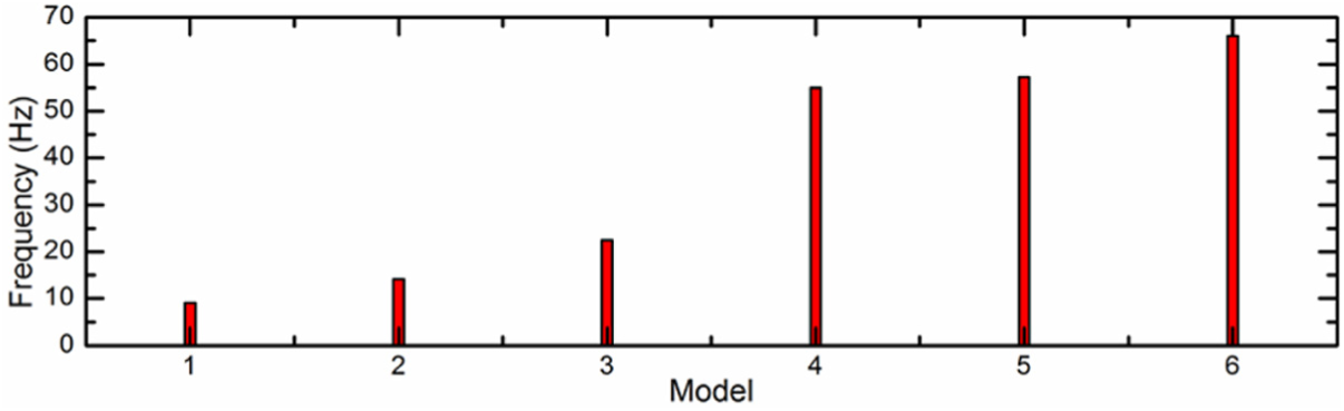
Modal analysis of the first six orders of the mast system.
According to the modal analysis results, the lowest frequency of the mast was 9 Hz, which satisfied the design requirement in terms of control bandwidth. The displacement and acceleration of the harmonic response of the mast are presented in Figure 4.
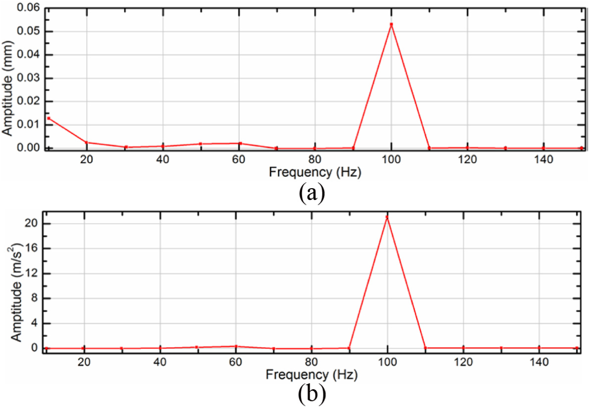
The harmonic response of the mast: (a) displacement and (b) acceleration.
The analysis showed that common resonant frequency was approximately 100 Hz. Therefore, that frequency should be avoided in mast design to overcome the adverse effects induced by resonance, fatigue and forced vibration.
Analysis of forces on the mast
In the work mode, the mast is subjected to loading pressure and wind load. As the main load for the high-rise structures, the wind load can be regarded as a main factor that affects the swaying of the mast.10–12
In this case, wind load can be defined by

where C is the wind factor, Kh is the variation coefficient of wind pressure height, q is the calculated wind pressure in N/m2, and A is the windward area perpendicular to the wind direction in m2.
Wind factor C
Wind factor is dependent on structure shape and size. For the frame structure made up of cylindrical tubes, the wind factor C = 1.3.
Variation coefficient of wind pressure height Kh.
For the mast with the height of 12 m, the variation of wind pressure height can be neglected, that is, Kh = 1.
Calculated wind pressure q
Wind pressure is correlated with air density and wind speed and can be calculated using the equation

where q is the calculated wind pressure in N/m2, and v is the calculated wind speed in m/s.
Windward area A
The windward area of the mast structure represents the projected area perpendicular to the windward plane, that is, the area projected in the direction that is the most unfavorable for windward. The windward area can be calculated using the equation

where A1 is the outer contour area of the structure, and φ is the filling ratio of the structure (i.e. the percentages of vertically projected areas of various faces of the mast to the projected rectangular area of the mast). In this study φ = 0.4.
For the experiments conducted in a fresh breeze condition, the mast was subjected to the wind load of approximately 213 N at the wind speed of 8.0–13.8 m/s.
Field experiments
Experimental setup
To gain the tracking precision and performances of vehicle-mounted optical transceiver, we conducted a series of field experiments. The experiments are determined to (1) inspect whether the designed vehicle-mounted optical transceiver satisfies the technical requirements and (2) validate the performances and indexes of the mast prototype in the real operating conditions. Generally, the experimental system was mainly composed of swaying platform, vehicle-mounted optical transceiver, motion target, vibration tester and spectrum analyzer. The structure of the tracking-precision test system of vehicle-mounted optical transceiver is illustrated in Figure 5.
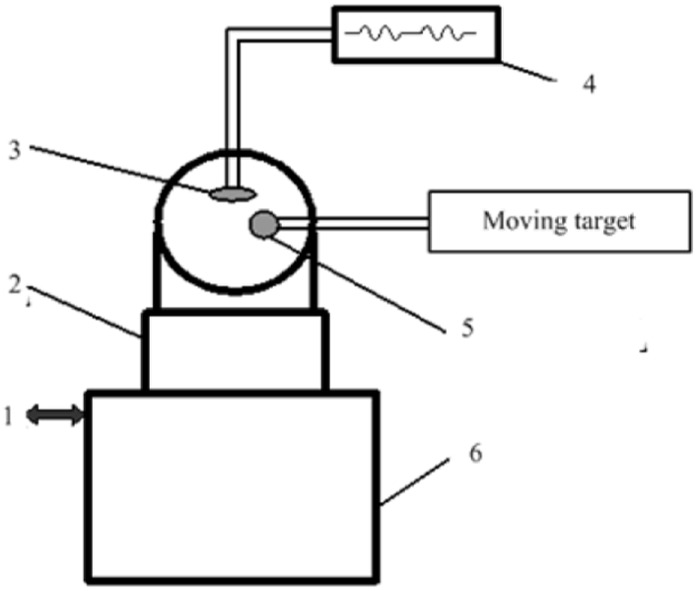
The structure of the tracking-precision test system.
The communication optical transceiver was subjected to two types of vibrations. First, in idling condition, the generator of a carrier vehicle can produce a vibration at a fixed frequency, which is transmitted to the optical transceiver via the mast. Based on the modal analysis and practical vibration test results, this kind of vibration can be neglected, since the optical transceiver is not that sensitive to the mast. Second, wind load, on the other hand, can induce a low-frequency large-amplitude swaying vibration that has a great effect on the optical transceiver.
To examine performances of the mast in a real operating environment, we also conducted the field experiments on the mast prototype. Since only one carrier vehicle was used, one optical transceiver was set up in the laboratory and the other one was set up on the mast. The field experimental setup is presented in Figure 6.
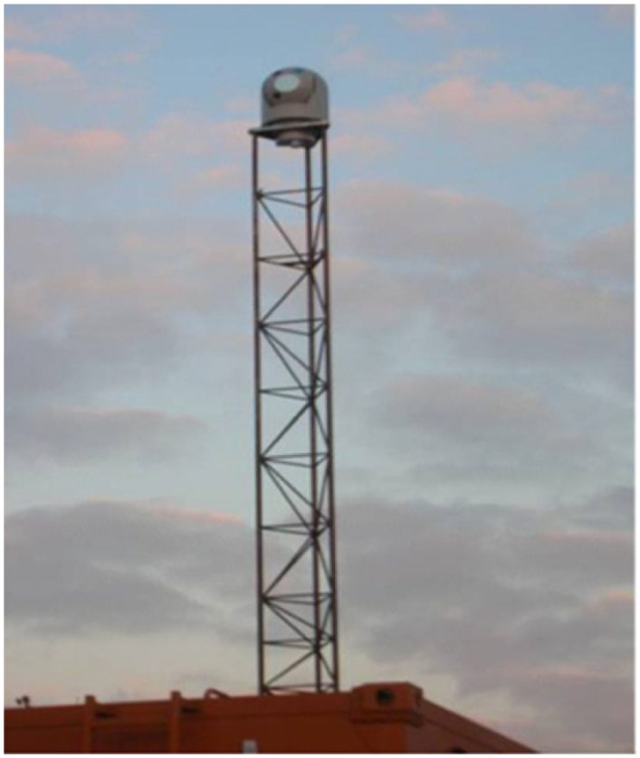
The field experimental setup.
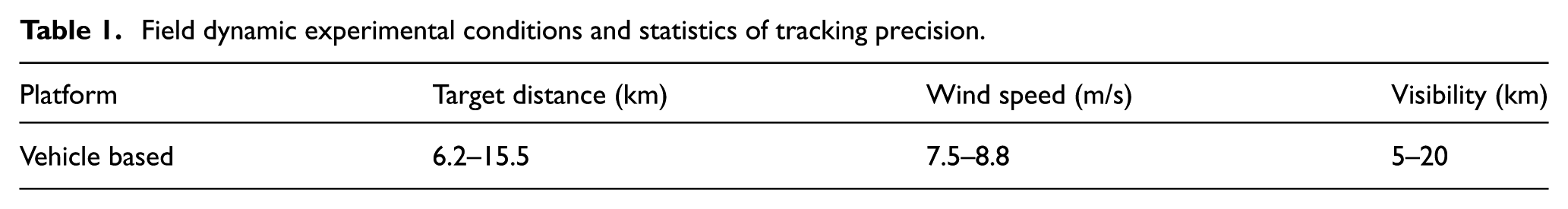
For the field experiments, the distance between two optical transceivers was measured by the global positioning system (GPS), and the environmental wind speed was measured by the wind speed meter. In addition, the vibration of the mast top, that is, the installation base of the optical transceiver, was measured by the vibration tester. In addition, the error rate in communication was measured by the bit-error tester. Considering that a large number of experiments were recorded, data process is required to acquire the tracking-precision and communication error rate of the optical transceiver. After data processing, the performances of the optical transceiver were concluded. The experimental parameters and all related statistical results are given in Table 1.
Field dynamic experimental conditions and statistics of tracking precision.
After the optical transceiver was debugged, the vibration characteristics of the mast top caused by the wind load were simulated on the swaying platform, and vibrations were also obtained from the vibration tester.
Error analysis of the test system
For the experimental platform, the devices were installed as accurately as possible in order to guarantee the normal debugging and test precision of the system. However, the following errors were inevitable.
Mechanical adjustment error (δ1)
In the experiments, in order to accurately measure the tracking precision of the vehicle-mounted optical transceiver, the target surface of the tracking camera should be perpendicular to its axis of beacon beam; however, δ1 was inevitably introduced in the camera adjustment. In this study, δ1 was smaller than 1 µrad.
Imaging error of CCD camera (δ2)
In this study, the P2-4x-08K40 charge-coupled device (CCD) camera was used, and the error induced by the non-uniform insensitivity of photosensitive units can be defined as

where the saturated output voltage (Vsat) was 3 V. According to the experimental data, the error curve was plotted and fitted, and the curve slope around the edge (denoted as k) was calculated.
Therefore, the error induced by the non-uniform sensitivity of CCD photosensitive units can be calculated using the equation

where k was approximately 15 mV/μm and δR was relatively large. Therefore, the CCD imaging error was δ2 = 0.2 µrad.
Error of the light path (δ3)
Compared with the optimal axis, the error in the light path was assumed as 0.5 µrad in this study.
Vibration error (δ4)
Vibration error is also an important error source in the experiments. The experimental data revealed that the vibration error δ4 was smaller than 0.5 µrad.
Other errors (δ5)
Other factors, such as the interference in transmission lines, atmospheric agitation and ambient temperature change, may also effect of system performances. Based on the engineering experience, these errors were normally less than 1 µrad.
Assuming that all aforementioned errors have normal distribution, the overall error of the system can be calculated using the equation
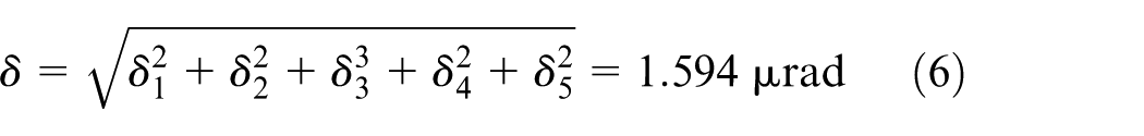
The analysis of experimental results showed that the overall error satisfied predefined system requirements.
Results and analysis
The measured vibration characteristics of the mast at a sampling frequency of 2000 Hz are presented in Figure 7.
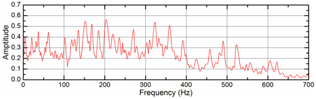
Measured vibration characteristics of the mast.
In Figure 7, it can be observed that the maximal vibration amplitude is 0.56 and the corresponding frequency is 202.14 Hz, wherein we can observe that the maximal vibration amplitude is 200 Hz.
The swaying characteristics of the mast are presented in Figure 8.
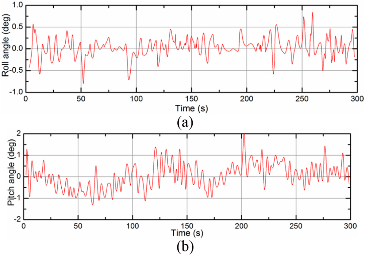
Swaying characteristics of the mast: (a) roll angle and (b) pitch angle.
As shown in the Figure 8, the roll angle is less than 1° and the pitch angle is varied between −2° and 2°, which meets the requirement. Furthermore, the measured tracking errors of the mast are presented in Figure 9.
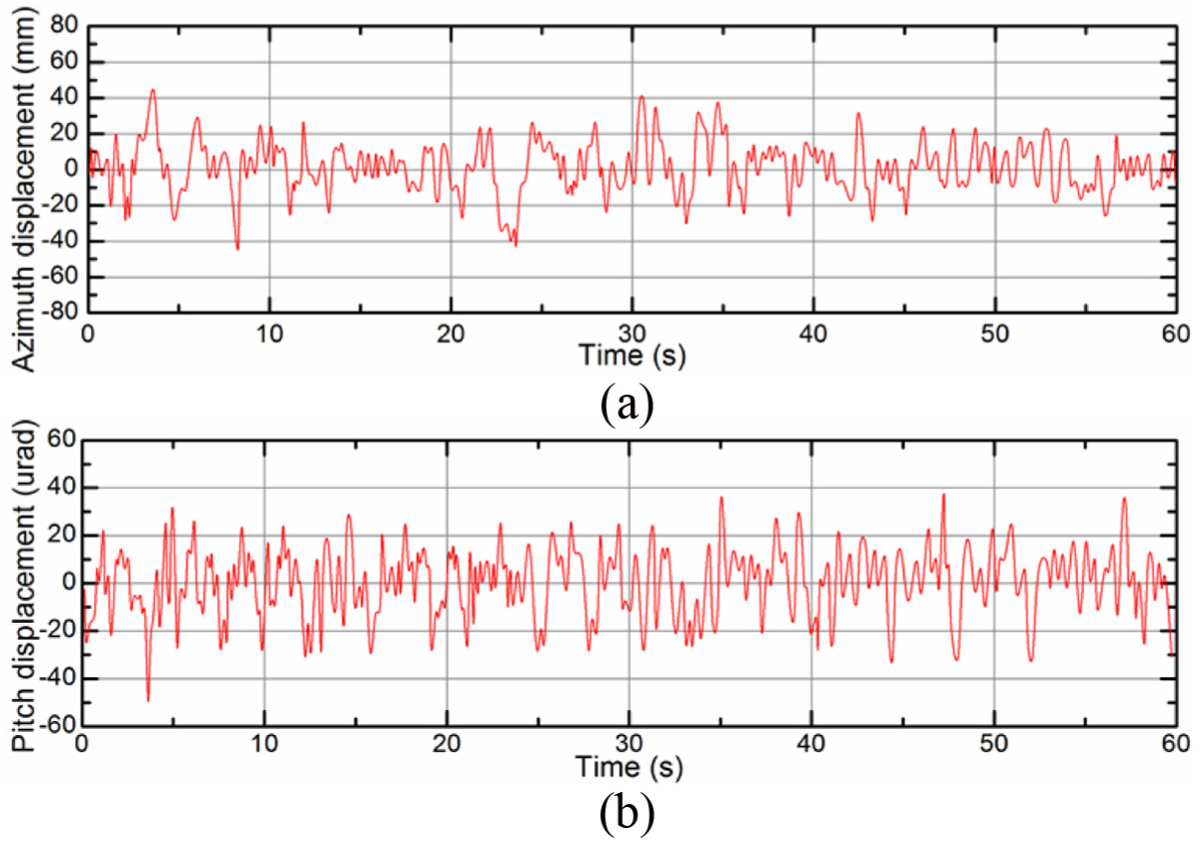
Tracking errors of the mast: (a) azimuth displacement and (b) pitch displacement.
It can be obtained from the figure that both the azimuth and pitch displacement is varied from −60 to 60 µrad. Through the statistics, the test results were acquired and are listed in Table 2.
Field test results of the dynamic tracking precision of the mast system
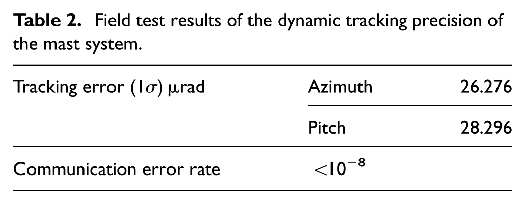
The experimental results showed that even in different dynamic conditions with different wind speeds and vibrations, the tracking error of the system also satisfies the design requirements, which further validates the feasibility of the designed mast.
Conclusion
This study reviews the vibration performance of a guyed mast with the height of 12 m, considering the wind load in the ambient condition. Detailed conclusions are as follows:
To achieve the rapid and accurate coarse tracking for the optical transceiver, it is feasible to design the guyed mast, considering that there is no relevant research to refer, and the ambient environment involved with the effect of the wind load is relatively complicated. Furthermore, the guyed mast used in this work is also useful to lead the engineering application in the laser communication industry, especially for the communication between multiple optical transceivers.
According to the experimental results, the tracking error of the vehicle-mounted optical transceiver is less than 80 µrad which satisfies the design requirements in all conditions. However, when the wind effects are considered, the guyed mast is very sensitive to the wind motions. Since the behavior is unpredictable and nonlinear, a detailed modeling study seems necessary for further study.
To avoid any effect of excessive vibrations on the tracking accuracy of the optical transceiver, the amplitude of the resonant frequency of 100 Hz is considered. In addition, when the loading weight is 60 kg, the height of the mast should not be higher than 12 m, since the tracking accuracy may not meet the requirements for the laser communication. Also, further work will be focused on the long-range and high-speed space laser communication testing which will be conducted on two fixed-wing Y12 helicopters.
Footnotes
Acknowledgements
The authors thank the Collaborative Innovation Center of High-End Equipment Manufacturing Equipment in Fujian Province of China for applying the experimental field.
Declaration of conflicting interests
The author(s) declared no potential conflicts of interest with respect to the research, authorship and/or publication of this article.
Funding
This project was supported by the National Natural Science Foundation of China (grant no.: 51505087).