
Abstract
This paper presented the brushless direct current motor torque ripple reduction based on the speed and torque control using hybrid technique. The dynamic behavior of the brushless direct current motor is analyzed in terms of the parameters such as the speed, current, back electromotive force and torque. Based on the parameters, the motor speed is controlled and minimized the torque ripples. For controlling the speed of the brushless direct current motor is utilized the fractional-order proportional–integral–derivative controller for generating the optimal control pulses. With the use of fractional-order proportional–integral–derivative controller, the optimal gain parameters are needed to reduce the torque ripples and control the speed of brushless direct current motor. By utilizing the hybrid technique, the gain parameters are utilized to analyze the optimal gain parameters of fractional-order proportional–integral–derivative controller. The hybrid technique is the combination of adaptive neuro-fuzzy inference system with firefly algorithm. The proposed strategy is simple in structure and robust to reduce the complexities of the mathematical computations. Initially, the nature inspired optimization algorithm of firefly algorithm is analyzed for finding the error function. In addition, the efficient adaptive neuro-fuzzy inference system controller which becomes an integrated method of approach is performed to control the error functions in order to yields excellent optimized gain values. After that, the control signals are applied to the input of voltage source converter of brushless direct current motor. With this control strategy, the harmonics and torque ripples are minimized. Based on the proposed control strategy, the speed and torque performance is analyzed. The effectiveness of the proposed technique is implemented in MATLAB/Simulink platform and evaluates their performance. The performance analysis of the proposed method is demonstrated and contrasted with the existing techniques such as bat algorithm, particle swarm optimization algorithm and ant–lion optimizer algorithm with fractional-order proportional–integral–derivative controller techniques.
Keywords
Introduction
Electric drives form an integral part of industrial plants with over 5 billion motors built worldwide every year. Typical residential and commercial applications tend to use conventional motor drive technologies, such as single-phase induction or brushed direct current (DC) motors. However, these machines are characterized by low efficiency and high maintenance, respectively. The last decade has also seen an increase in the use of variable-speed generators for wind generation and hydro-generation for sustainable energy production in rural and urban areas. 1 A brushless direct current (BLDC) motors are extensively used in industrial, domestic and medical applications because of no brush and no commutator, wide speed range, simple structure, high power density, large torque-to-current ratio, relatively high efficiency and good controllability over a wide range of speed. 2 BLDC motors can be classified into two categories as surface mounted permanent-magnet BLDC motors and interior permanent-magnet BLDC motors. 3 The speed regulation is an important aspect in the field of BLDC motor drive for precise speed and position control applications. 4 The speed response has larger overshoot in transient period and more fluctuation during the steady-state period. 5 As a typical speed control system, BLDC motor double-loop speed regulation system has been widely used in automotive electronics, home appliances, office automation and precision machine tools. 6 There are many modern control methodologies such as non-linear control, optimal control variable structure control and adaptive control have been widely utilized for speed control of a BLDC motor. 7 Tariq et al. 8 have presented an anti-windup drives for BLDC motor. Most of the BLDC motors drive adopts proportional–integral–derivative (PID) controller and pulse-width modulation (PWM) scheme for speed control. Premkumar and Manikandan 9 have presented a design of fuzzy proportional derivative controller and fuzzy PID controller for speed control of BLDC drive. Kumar and Singh 10 have presented a solar photovoltaic (SPV)-powered BLDC motor drive for water pumping.
Li et al. 11 have presented a method for position sensorless control of high-speed BLDC motors with low inductance and non-ideal back electromotive force (EMF) in order to improve the reliability of the motor system of a magnetically suspended control moment gyro (MSCMG) for space application. Das et al. 12 have established a utilization of renewable energy sources has been emphasized in high-raised buildings, where DC micro-grid. Hence, this paper enunciates the scope of using BLDC motors for elevator systems suitable for operating with DC micro-grid. However, these approaches are either complex in theoretical basics or difficult to implement. The torque ripple commonly existing in the BLDC motor restricts its application in high-precision drive system. The torque ripple in BLDC motor is caused by many reasons, especially the commutation torque ripple. Hence, suppression of commutation torque ripple becomes the key to reduce the BLDC motor torque ripple. 13 The torque mainly includes cogging torque, reluctance torque and mutual torque, among which the cogging torque is induced by the stator slots interacting with the rotor magnetic field and is independent of stator current excitation. 14 And, reluctance torque is caused by the variation in phase inductance with respect to position, while mutual torque is created by the mutual coupling between the stator winding current and rotor magnetic field. 15
However, the obvious torque ripple which is caused by the non-ideal trapezoidal back EMF waveform and the non-ideal commutation of phase current really restricts its application in high-precision and high-stability occasions. Hence, the torque ripple minimization is highly concerned by researchers in recent years. 16 Torque ripples are occurred due to the power electronic commutation, the usage of high-frequency switching power devices, imperfections in the stator and the associated control system, the input supply voltage to the motor contains various harmonic components and the pulsating current input due to electronic commutation are also causes for torque ripples.17,18 So, an efficient controller is required to reduce the harmonics present in the input voltage to the motor and to reduce the pulsating variation of line current to the motor. 19
Optimal torque control schemes for BLDC motors reducing torque ripples and controlling the speed have been utilized. 20 So far, many methods have been proposed to suppress the torque ripple. Such as the overlap of the phase change method, the hysteresis current method, the PWM method, the current predictive control method, the direct torque control (DTC) and so on, but those methods inevitably exists the problem of over or under compensation, which may affect the effect of the torque ripple suppression.21,22 For most of the BLDC control approaches, rotor speed and position information are essential. One can either use sensors to measure the speed and position or some estimation techniques can be employed to obtain the speed and position. 23 Proportional–integral (PI)-based speed controller has been implemented for BLDC motor, but the controller has produced large settling time, rise time and more oscillations in the speed response. 24 Conventionally, least-squares approximation method, genetic algorithm (GA), particle swarm optimization (PSO) algorithm, neural network (NN) and improved gradient descent algorithm was utilized. 25
El-samahy and Shamseldin 26 have compared the performance of two different control techniques applied to high-performance BLDC motor. The first scheme is self-tuning fuzzy PID controller and the second scheme is model reference adaptive control (MRAC) with PID compensator. Nag et al. 27 have proposed BLDC motors, which are widely used in various low-power drive applications owing to their several advantages over conventional motors. Zhou et al. 28 have proposed a sensorless salient-pole BLDCM-DTC drive system. A stator current estimator with back EMF self-adaptation is first constructed according to stator current state equations and the back EMF is obtained by adaptive law.
Liu and Zhang 29 have proposed a DTC method for BLDC motors based on duty ratio control, and it is proposed to reduce torque ripple and maintain a constant switching frequency. Conventional DTC suffers from large torque ripple and non-constant switching frequency, which are caused by the hysteresis band amplitude and the motor speed. Many methods have been proposed to tackle these problems. However, these methods are usually complicated and parameter dependent. Potnuru et al. 16 have presented a rapid control prototyping implementation of closed-loop speed control for a BLDC motor drive. Generally, control algorithms which are developed for the motor drive might show good simulation results during steady-state and transient conditions; however, real-time performance of the drive greatly depends on execution of real-time control software, speed and position measurements and data acquisition.
Nowadays, the speed and torque control of BLDC motors is the one of the important topic which has increased the attention in the research field. The advantages of BLDC motors are provide high reliability, high efficiency, low maintenance, and so on. Conventionally, many number of speed and torque controllers have been developed for the speed control of BLDC motor. They are classified as PID controller, fuzzy logic–based controller, neuro-fuzzy controller, and so on. Normally, PID controller is an optimum choice for controlling the speed of the BLDC motor. However, it has uncertainty problem due to load as well as in set speed variations. Also, tuning of the PID controller leads to uncertainty in the control system parameters. In order to overcome the above problems, precise method of control can be provided with help of intelligent system based on fuzzy logic and NN approach. While using NNs, which is trained offline using data from conventional PI controller. It will not provide the efficient dynamic response. In the fuzzy logic controller, the logical rules are generated, but it takes more time to execute or make the decision rules. But most of the time, fuzzy logic–based controller provides better results than the conventional and NN. From the literature review, the PI controller is the most preferable speed controller for BLDC motor, but PI controller produces sluggish response in the system, and also it produces uncertainty problem in some operating conditions of the BLDC motor. Recently, optimization algorithm–based PI controller are developed for controlling the torque and speed of BLDC motor such as, GA, PSO algorithm, and bat algorithm (BA). The GA operation is based on genetic operators, they are random in nature; therefore, it causes infeasible solution with excessive computational time. But in PSO algorithm, the velocity equation consists of stochastic variables so the global best value is varying uncertainly. To avoid these shortcomings, an efficient technique–based advanced PID controller is needed to solve the above issues of BLDC motor. Therefore, in the paper, an enhanced control strategy is proposed for solving the above issues. In this document, an enhanced fractional-order proportional–integral–derivative (FOPID) controller is employed for regulating the speed and minimizing the torque ripples in BLDC motor. Section “Proposed control scheme for speed control of BLDC motor” specifies the detailed description of the proposed method. In section “Results and discussion,” the results and discussion of the proposed methods is explained. Section “Conclusion” concludes the document.
Proposed control scheme for speed control of BLDC motor
In this section, the proposed control technique is utilized to regulate the speed and minimize the torque ripple of the BLDC motor. Here, the proposed hybrid technique–based FOPID controller is developed for controlling the speed and torque of BLDC motor. The hybrid technique is the combination of adaptive neuro-fuzzy inference system (ANFIS) with FA. Initially, the nature inspired optimization algorithm of FA is analyzed for finding the error function. Then, FA is utilized for offline training the ANFIS controller. In addition, the efficient ANFIS controller which becomes an integrated method of approach is performed to control the error functions in order to yield excellent optimized gain values. By utilizing the hybrid control topology, the speed regulation will achieved and the torque ripple will minimized. The control gain parameters are fed to the FOPID controller; it will be utilized for controlling speed and torque according to their control signals. And also the proposed control techniques are employed for enhancing the minimization of torque ripples. Then, the proposed hybrid technique–based FOPID controller performance is illustrated in Figure 1.
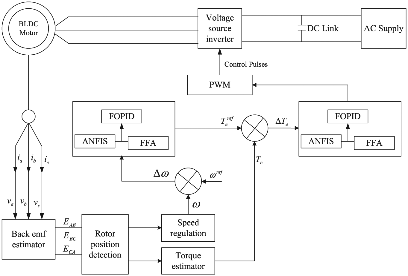
Proposed control structure of BLDC motor.
Above operation shows, initially, the AC supply is given to the input of rectifier as the output of the DC-link voltage is give to the voltage source inverter (VSI). In addition, the output of the AC supply is given to the BLDC motor corresponding load connection. Here, the commutations angles are internally connected to regulate the operation. Commutations ensures the proper rotor rotation of the BLDC motor and produce the back EMF, while the motor speed only depends on the amplitude of the applied voltage. The amplitude of the applied voltage is adjusted using the PWM technique. The required speed and torque is controlled by use of controller, which is implemented as a proposed FOPID-based hybrid technique. The performance of required proposed system and its controller action is investigated in the following section.
Modeling of BLDC motor
In this paper, a three-phase, two-pole BLDC motor is studied. The speed of the BLDC motor is controlled by means of a three-phase inverter. This kind of motor not only has the advantages of DC motor such as better velocity capability and no mechanical commutators but also has the advantages of AC motor such as simple structure, higher reliability and free maintenance. 31 The voltage equations of three windings with phase variables are given as equations (1)–(3)


And, the equation of the electromagnetic torque is given as equation (4)

where

Here,
Speed control strategy
The BLDC motor is driven by applied voltage also coupled with the back EMF. The generated stator flux interacts with the rotor flux, which is generated by a rotor magnet and defines the torque and thus the speed of the motor. At first, we analyzed the speed control of the BLDC motor. In working condition of BLDC motor, the output of speed is detected and the error value is controlled by introduce the proposed controller. The speed of the BLDC motor is taken and compared with the reference speed using comparator. The resulting error speed value is calculated as equation (6)

Here,
Torque control system
However, proposed controller technique is analyzed for minimization of torque ripples in motor operation. The high-speed operation is one of the most important situations that a motor should successfully undergo in order to overcome the big commutation-torque-ripple created. Under the creation of torque ripple, an improved approach has also been proposed to reduce the motor torque-ripples at high-speed for DTC strategy of three-phase BLDC motor with the proposed method. The resulting reference torque error value is get from the output of proposed speed controller, and the actual torque value is given to the input of the comparator. As the output of change in error value is produced, while the optimization process is considered. Here, the FOPID controller-based hybrid technique is improved to reduce the torque ripples. Finally, the optimized resulting value of duty cycle is given to the PWM purpose. Utilizing this improved approach, the electromagnetic torque remains constant without feeling any need to an accurate calculation of the duration of the applying effective proposed controller of the varying input voltage, and the motor torque-ripple, which derives from the uncontrollable conduction at high speed, is minimized.
Speed controlling process of the BLDC motor with FOPID controller
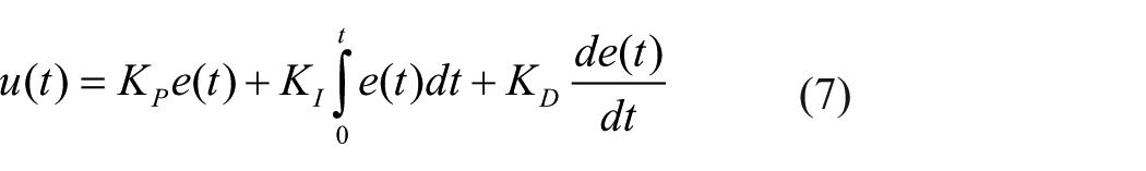
The reasons behind the use of FOPID controller are that it does not have any steady-state error, has gain and phase cross-over frequency and also the gain and phase margin and gives robustness from the variations in the phase cross-over frequency and the high-frequency noise. Numerically, the FOPID controller can be defined as equation (7)
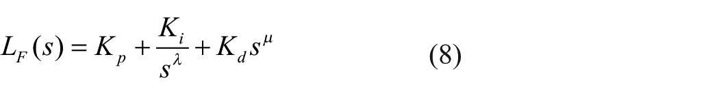
On performing the Laplace transform of the equation, we get equation (8)
where
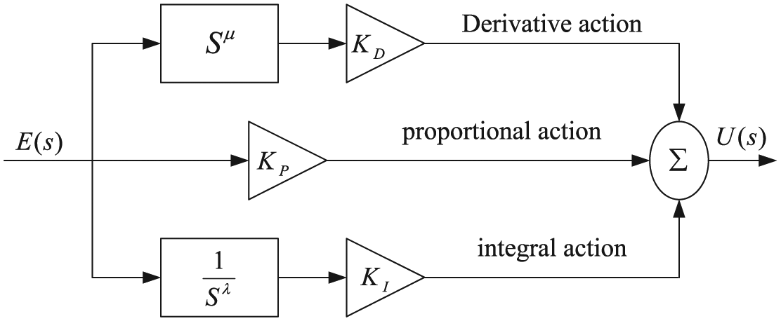
FOPID controller block diagram.
Conventional PID controller can be obtained by setting
The main motive behind the minimization of performance index is to enhance the stability margin of the hybrid system by obtaining better damping and thereby getting minimum increment in terminal voltage response. This indicates the minimization of the overshoot


It is always required to select a reference model to get the error function

Here,
Hybrid technique for gain optimization
The speed control of the BLDC motor is utilized with FOPID-based controller. The FOPID gain parameters are optimized based on the proposed hybrid techniques, which is the composite of ANFIS and FFA algorithm. The proposed system controller controls the speed based on the measured parameters of the BLDC motor. This process consists of two loops, namely, inner loop and outer loop. Inner loop is used for synchronizing the inverting gate signal with back EMF of the BLDC motor. The outer loop is used for controlling the speed of the BLDC motor by controlling the DC bus voltage through PWM inverter. Based on error and rate of change of error, ANFIS controller provides the control signal to the switching logic circuit. The ANFIS utilized the FFA for offline training based on the optimal training data set. The switching logic circuit provides the PWM signal for the inverter gate with respect to back EMF of the motor and the control signal output obtained from ANFIS controller.
ANFIS control scheme for speed control of BLDC motor
The modeling approach used by ANFIS is similar to many error minimization techniques. Generally, ANFIS model has five layers such as input layer, input and output membership layer, rules layer and output layer is hypothesized. Next, the input/output data are gathered for training the proposed system. ANFIS can be used to train the FFA to emulate the training data presented to it by modifying the parameters according to a chosen error criterion. Operation of ANFIS looks like feed-forward back propagation network. 39 Consequent parameters are calculated forward while premise parameters are calculated backward.
Figure 3 illustrated the control structure of ANFIS, which explains the process of the proposed error minimization technique. This inference system is used five layers to construct ANFIS. Each layer contains several nodes described by the node function. Adaptive nodes, denoted by squares, represent the parameter sets that are adjustable in these nodes, whereas fixed nodes, denoted by circles, represent the parameter sets that are fixed in the system. The output data from the nodes in the previous layers are the input in the present layer. 40 This section introduces the basics of ANFIS network architecture and its hybrid learning rule. The proposed technique objective function is evaluated by equation (13)

where

where


Here,
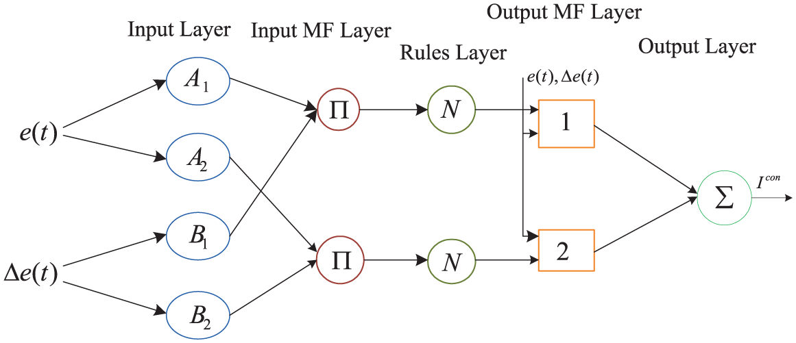
The proposed control structure of ANFIS.
To facilitate the learning (or adapting) of the Sugeno model, it is convenient to put the FFA into the framework of adaptive networks that can compute gradient vectors systematically.
41
Nodes within a layer of ANFIS perform similar tasks that are specified by their node functions, as described below. Note that
Layer 1
Layer 1 consists of input variables and each node of this layer generates the optimal position of an input variable with the node functions described as equations (18) and (19)


where
Layer 2
Layer 2 is membership layer and it checks for the weights of each membership functions. It receives the input values from the first layer and acts as optimal functions to represent the data sets of the respective input variables. The output node in these layer products all incoming signals as equation (20)

Layer 3
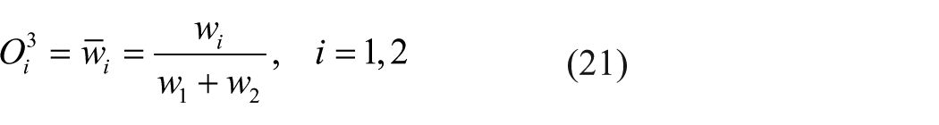
Layer 3 is called as rule layer and it receives input from the previous layer. Each node (each neuron) in this layer performs the pre-condition matching of the rules. This layer computes the activation level of each rule, and the number of layers equals to the number of fuzzy rules. Each node of this layer calculates the weights which will normalize. The nodes of the Layer 3 calculate the ratio of the rule’s firing strength relative to the sum of all rule’s firing strengths given by equation (21)
Layer 4
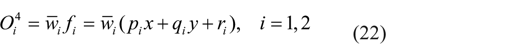
Layer 4 is the defuzzification layer which provides the output values resulting from the inference of rules. All nodes in the Layer 4 are the adaptive node with a node output is given as equation (22)
where
Layer 5
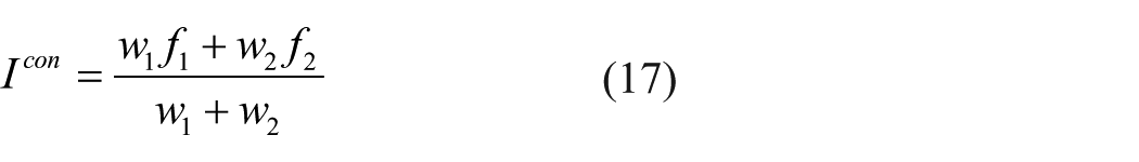
Layer 5 is called as the output layer which sums up all the inputs coming from Layer 4 and transforms the fuzzy classification results into a crisp value. Every node in Layer 5 computes the overall output as the summation of all incoming signals as equation (23)

The ANFIS structure is tuned automatically by least-square estimation and the back propagation algorithm. Because of its flexibility, the ANFIS strategy can be used for a wide range of control applications. The algorithm presented above is used in the proceeding section to develop the ANFIS controller for controlling the speed of BLDC motor. In the proposed control system, the ANFIS structure is trained by giving the vector as input. 42 Then, the appropriate control pulse output is given to the voltage source converter and generates the supply to BLDC motor based on the generated control pulse of the ANFIS.
FFA for selecting optimal training dataset
FFA is inspired by the flashing nature of fireflies. The firefly’s flash is used as a signal to attract other fireflies. The algorithm has three rules as follows:
All fireflies are unisexual, so one firefly will be attracted by all other fireflies.
Attractiveness is proportional to their brightness, and for any two fireflies, the less bright one will be attracted by the brighter one and thus move toward it, and the brightness decreases as the distance between the fireflies increases.
If there are no fireflies brighter than a given firefly, it will move randomly. 43
The brightness should be associated with the objective function. FA is the evolutionary computational technique also used to determine the controller parameters. Each firefly in FA represents a solution to the problem, and it is defined in terms of position. In d-dimensional vector space, the current position of

The random positions of
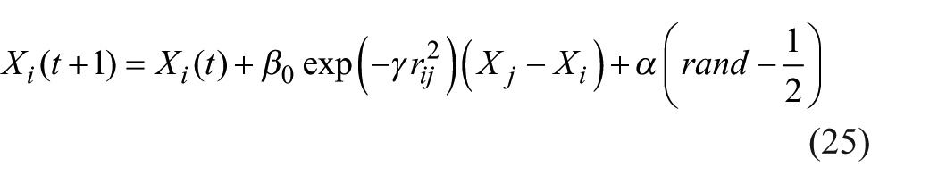
And, the position updating equation for the brightest firefly is given by equation (26)

where the first terms

where
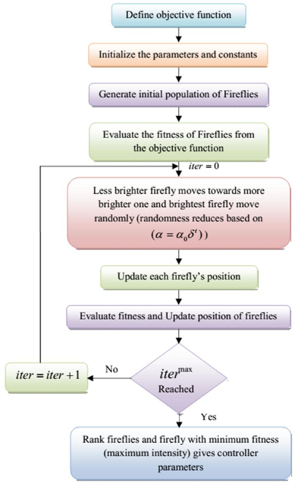
Flowchart of firefly algorithm.
Once updating of premise and consequent parameters is completed, proper set of membership function and rule base are selected for fuzzy inference system. After proper rules are selected and fired, the control signal required to obtain the optimal output is generated. To train the ANFIS controller, the network is trained offline using MATLAB/Simulink tool box. To start with, the result of FFA Tuned FOPID controller is collected as the training data set. The input and output data obtained are modified into desired data based upon the desired output. The desired output will trained using the function ANFIS in the MATLAB tool box. From the training, a fuzzy inference system with adjusted membership functions has been obtained. Then, the projected technique is executed in the MATLAB/Simulink platform and the achieved evaluations are explained in section “Results and discussion.”
Results and discussion
In this section, the performance analysis of the proposed hybrid technique is controlled the speed for reducing the torque ripple of the BLDC motor is evaluated and compared with the existing techniques like PSO, BA, ant–lion optimizer (ALO). The proposed hybrid technique is the combination of ANFIS and FFA, which regulates the speed based on the power parameters of the BLDC motor. The proposed technique is applied with Intel® core™ i5 processor, 4GB RAM and MATLAB/Simulink 7.10.0 (R2015a) platform. The Simulation model of the proposed system is illustrated in Figure 5, which is used to reduce the torque ripple of the BLDC motor with the help of proposed technique. Here, the proposed technique reduces the torque ripple and stabilizing the speed of the BLDC motor. Initially, the controlling parameters are measured from the BLDC motor like torque and back EMF.
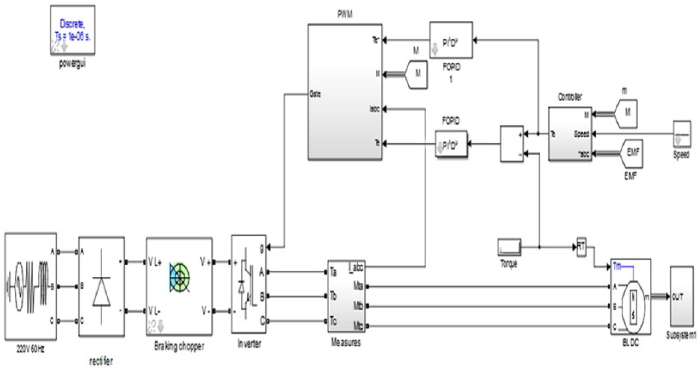
Implementation model of the proposed system.
In an implementation time the BLDC motor parameters are measured for evaluating the performance of the system, which is presented in Table 1. Then, the proposed technique is evaluated with three cases and compared with existing techniques. The three cases are based on the speed of the BLDC motor like small, average and top. In these cases are given as follows:
Case 1: the performance evaluation with small speed.
Case 2: the performance evaluation with average speed.
Case 3: the performance evaluation with top speed.
Implementation parameters of BLDC motor.
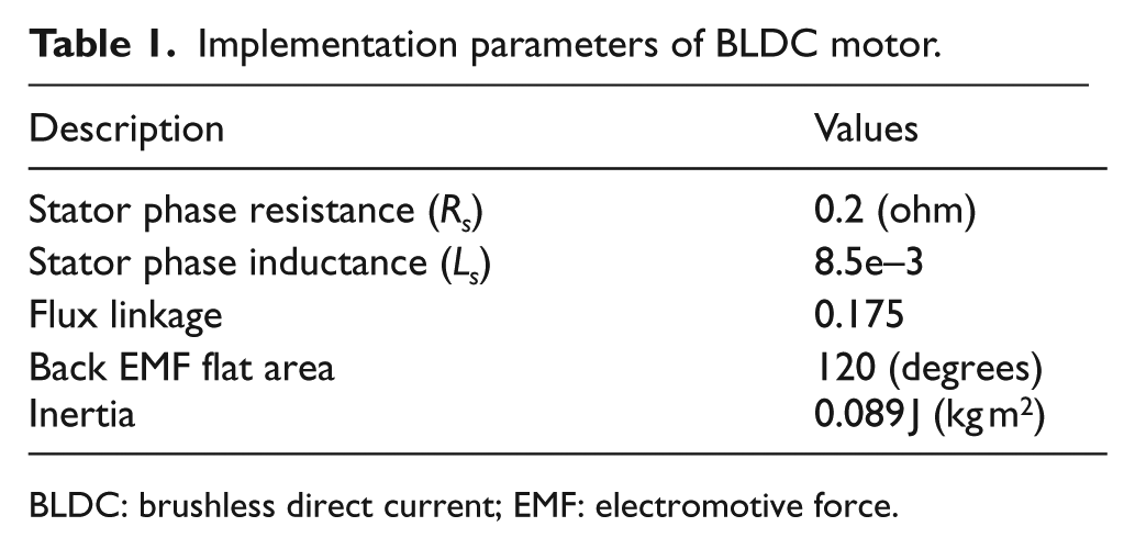
BLDC: brushless direct current; EMF: electromotive force.
In these cases, the reference speed and torque of the BLDC motor is varied, that is, 500 r/min and 8 N m for case 1, 750 r/min and 7 N m for case 2 and 1000 r/min and 8 N m for case 3. At first, the BLDC motor parameters are measured like current and back EMF; from the measured parameters, the torque is assessed. The speed of the BLDC motor is assessed and the reference torque is assessed from the variation of instant and actual speed of the motor. At last, the control pulse for PWM depends on the error value between the actual torque and reference torque of the BLDC motor. From that point onward, the parameters are assessed and delineated as takes after:
Case 1: the performance evaluation with small speed.
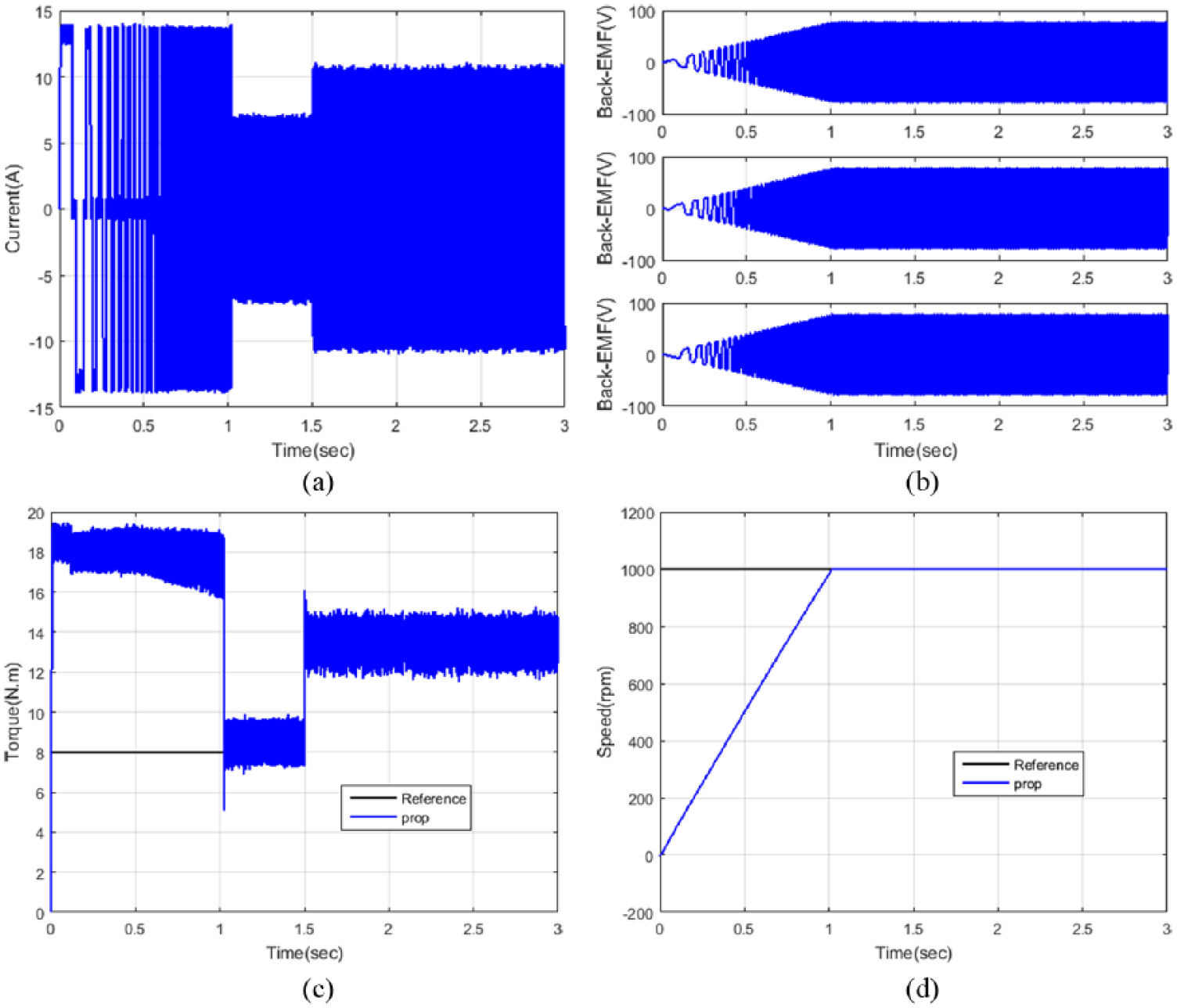
For this situation, the torque ripple is minimized based on the regulated speed and torque of the motor. The speed of the motor is controlled based on the input parameters of the motor like back EMF and current. The torque, back EMF and speed based on the input current are described in Figure 6. In view of the input current of the BLDC motor, the torque is changed inside 1.5 s, and after that, it holds the steady torque. Be that as it may, the speed of the motor is 0.5 s to achieve the reference speed; after the steady speed, just the EMF comes stable.
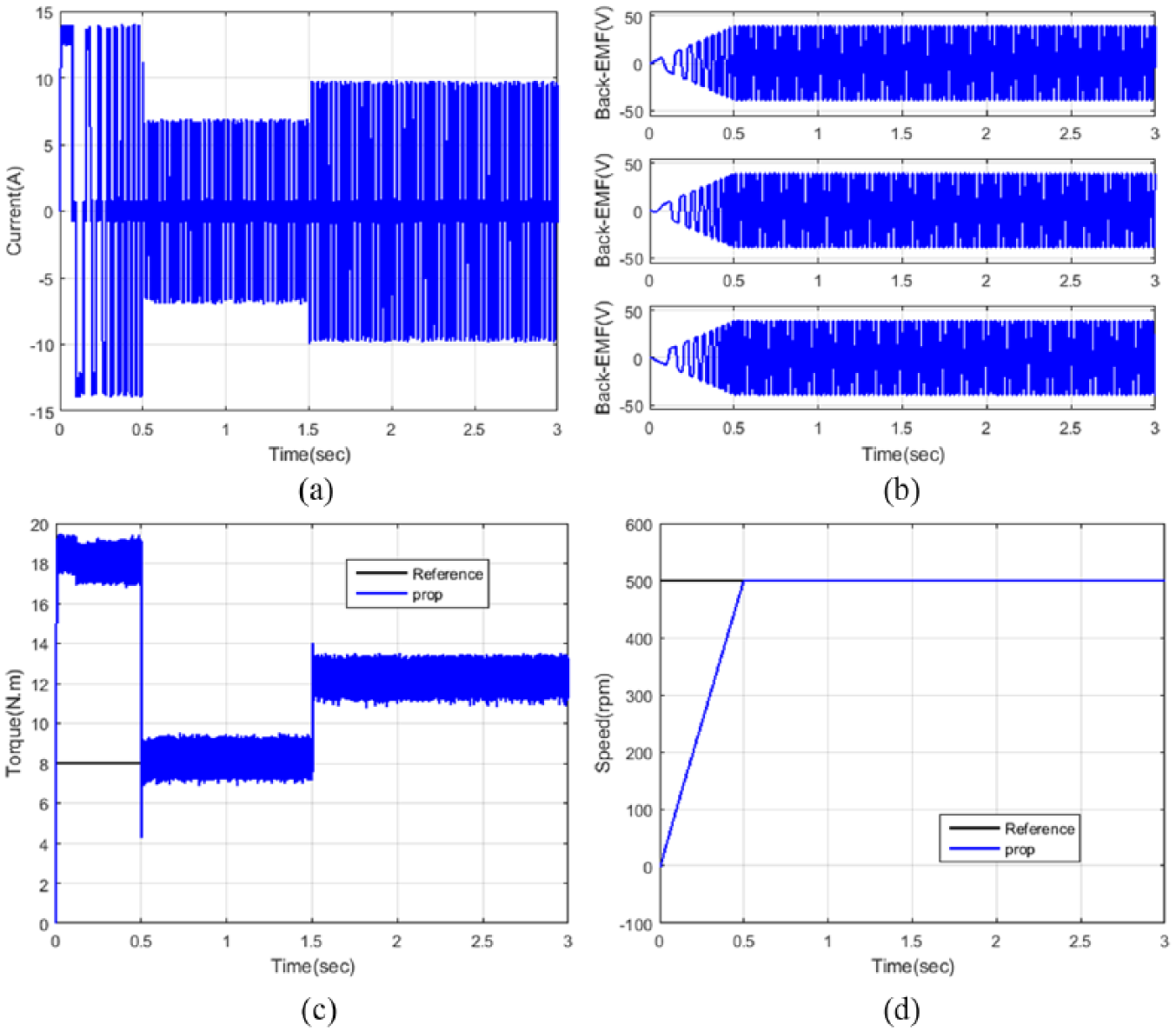
The dynamic parameters: (a) current, (b) back EMF, (c) torque and (d) speed estimation in case 1.
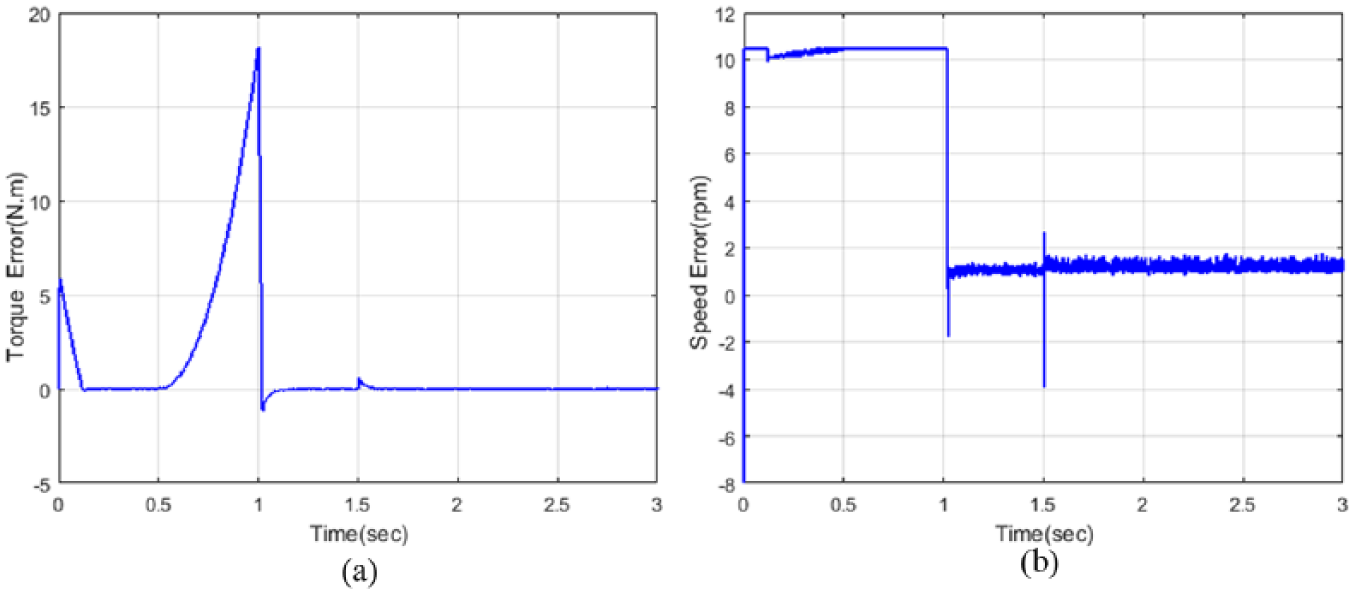
Then, the error value of the torque and the speed is illustrated in Figure 7, which is estimated from the variation of previous speed to the instant speed values of the proposed system. Then, the performance analysis is evaluated with the reference speed and torque for proving the performance of the 750 r/min speed and 8 N m, which is better than small speed level.
Case 2: the performance evaluation with average speed.
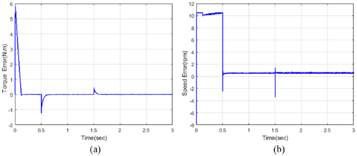
The dynamic parameters: (a) torque and (b) speed error values in case 1.
In this case, the ripple minimization performance is evaluated with 750 r/min reference speed and 7 N m torque, and the parameters are estimated and illustrated in Figure 8. Initially the torque of the motor is 18 N m, after the torque is 0.75 s once it reached the reference torque then the torque is constant after 1.5 sec, which are all based on the input parameters of the BLDC motor. The input current is controlled based on the speed and back EMF of the motor.
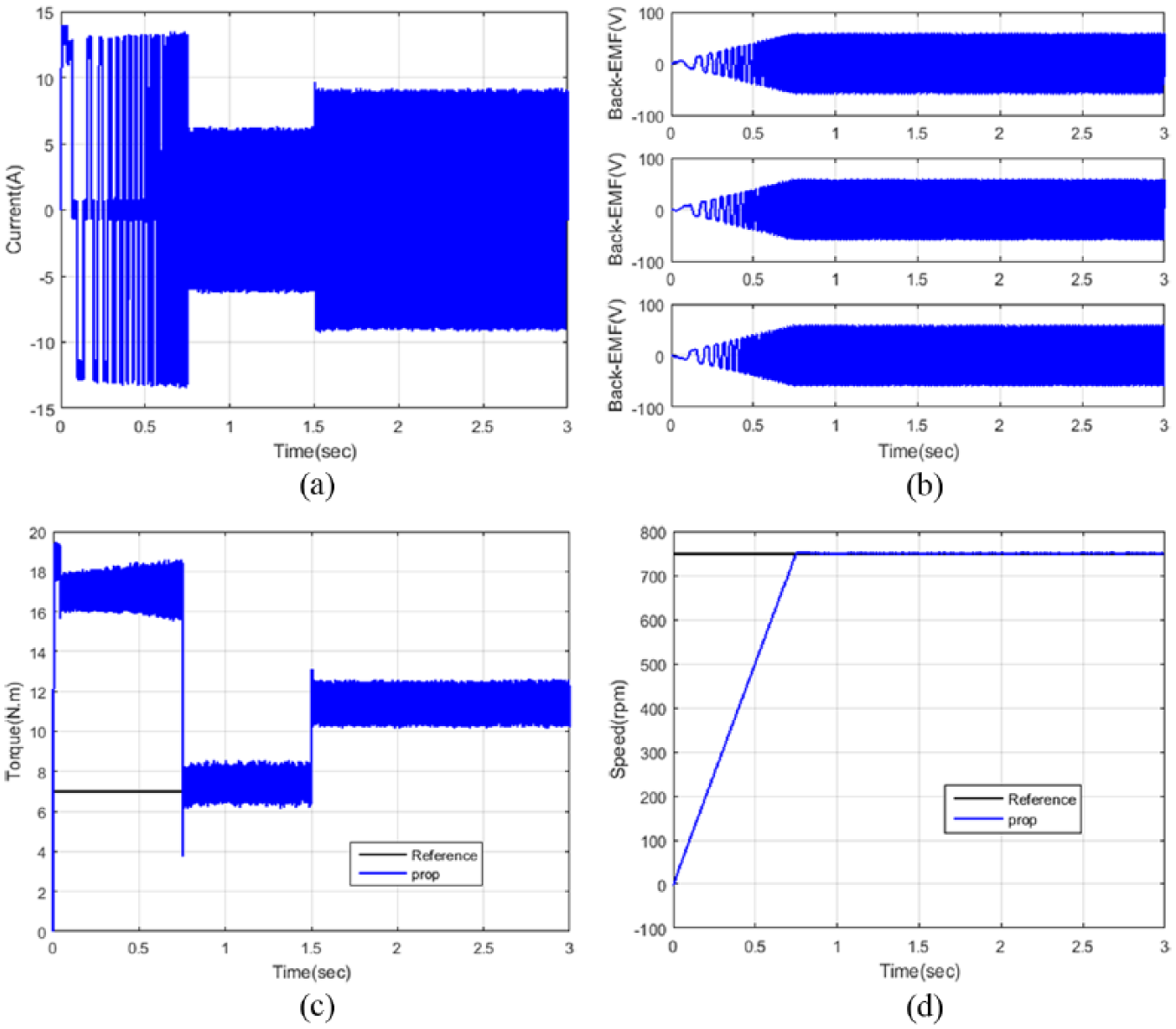
The dynamic parameters: (a) current, (b) back EMF, (c) torque and (d) speed estimation in case 2.
Based on the error value, the performance is evaluated for proposed technique and other conventional techniques, and then, the proposed technique torque and speed error value are evaluated in Figure 9. The error value is minimized based on the proposed technique, for minimizing the torque ripple from the BLDC motor speed and torque.
Case 3: the performance evaluation with top speed.
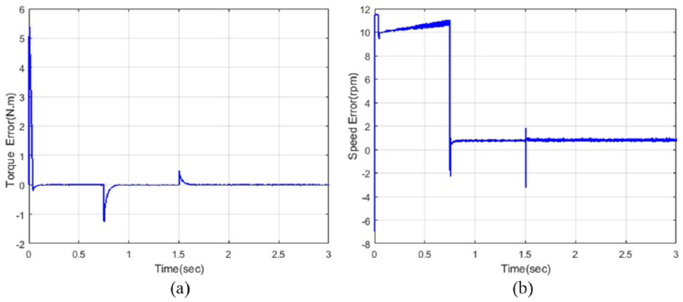
The dynamic parameters: (a) torque and (b) speed error values in case 2.
In this case, the reference speed is 1000 r/min and torque is 8 N m, based on the speed the torque and EMF is evaluated. If it is not stable to control the input parameters of the BLDC and so the limited input regulated current also speed correspondingly. The dynamic parameters are measured and illustrated in Figure 10, which illustrates the input current, torque, back EMF and speed of the BLDC motor. Finally, the dynamic parameters error value is evaluated from the BLDC motor and illustrated in Figure 11. Moreover, to prove the effectiveness of the proposed technique performance from the existing technique, the comparison analysis is performed as follows.
The dynamic parameters: (a) current, (b) back EMF, (c) torque and (10) speed estimation in case 3.
The dynamic parameters: (a) torque and (b) speed error values in case 3.
Comparison analysis of the proposed technique
From the performance analysis, the proposed technique is compared with the existing technique based on the torque and speed of the BLDC motor. In this comparison analysis, the three cases based on the torque are illustrated in Figure 12. In this figure, the time period 1.5 -1.54 some oscillation is occurred; based on the oscillation which shows the proposed FFAbased ANFIS technique is better than in an all cases.
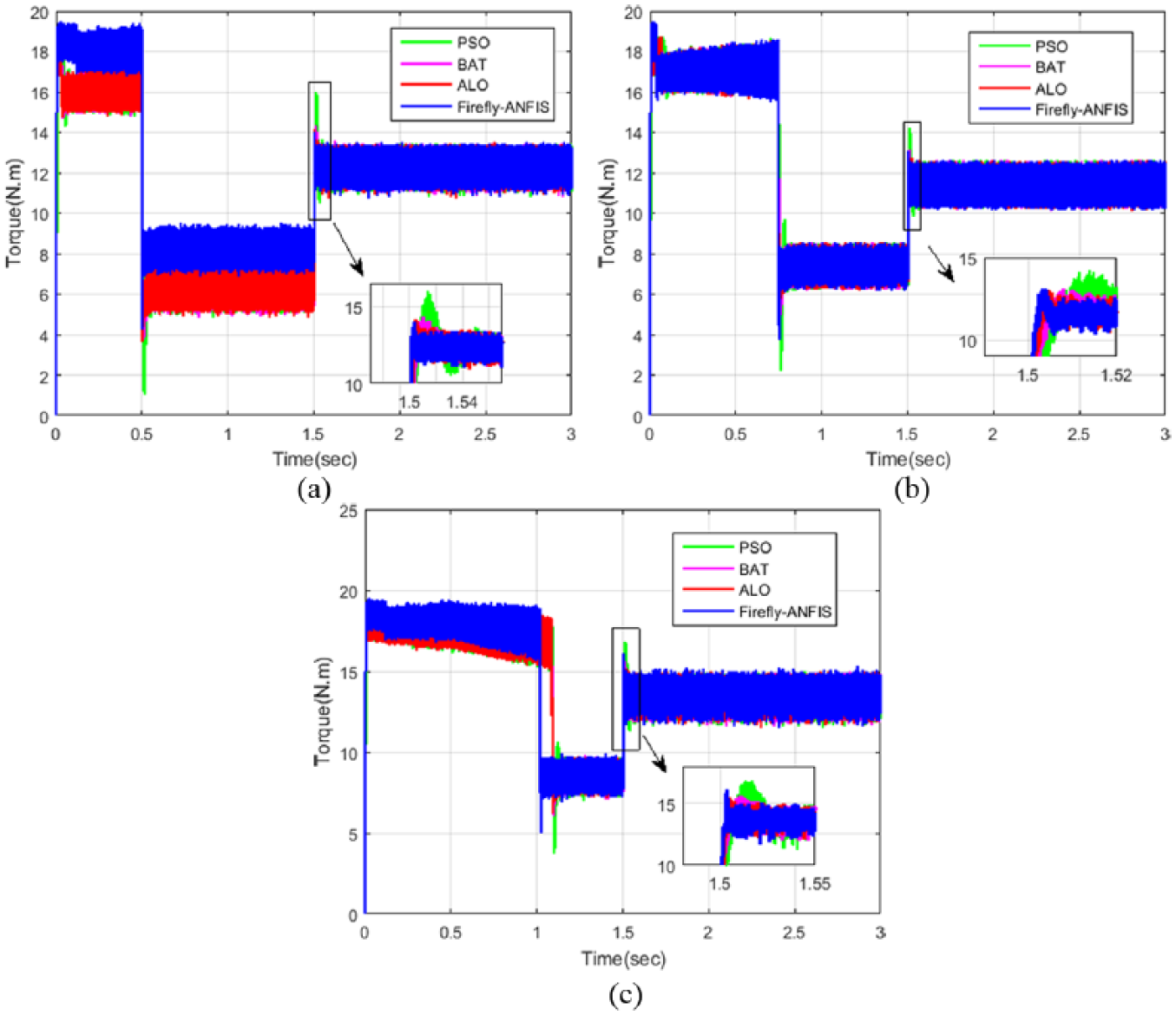
The comparison analysis of torque in (a) case 1, (b) case 2 and (c) case 3.
Finally, the speed of the proposed BLDC motor is evaluated and analyzed with existing techniques. The speed depends on the input parameters of the motor, so to control the input current based on the torque of the BLDC motor. The speed comparison of the proposed technique with the three cases are illustrated in Figure 13, which explains the estimated speed of proposed technique with cases 1, 2 and 3. In this figure, the variation time is focused and mentioned 0.95–1.2 s. From the overall analysis, the speed and torque performances of BLDC motor are done in different speed variations. The simulation results uncover that the proposed FOPID controller tracks the speed nearly to the reference speed of BLDC motor. It can be seen that the proposed strategy has much smaller speed ripple, where speed stability is better than that of the routine strategies. From the comparison analysis, torque and speed curves of three cases are examined and clearly shown that the proposed strategy significantly enhances torque performance, has much smaller torque ripple and exhibits good dynamic and steady-state performance. Then, the torque performance of the proposed method is superior to that of the existing methods like BA, PSO algorithm and ALO algorithm. Here, the settling time, rising time and overshoot time of the proposed is analyzed. In case 1, by using the proposed analysis the rising, settling and overshoot time is 0.002, 1.08 sec and 0 sec. While using BA, PSO algorithm and ALO algorithm, the rise times are 0.5, 0.7, 0, 0.45, 0.35, 0, 0.35, 0.25 and 0 s, respectively. At the same time the torque ripples of the proposed system is better in reduction as compared with the existing method. So, the proposed method achieves less time for rise time, settling time and overshoot time when compared to the other techniques.
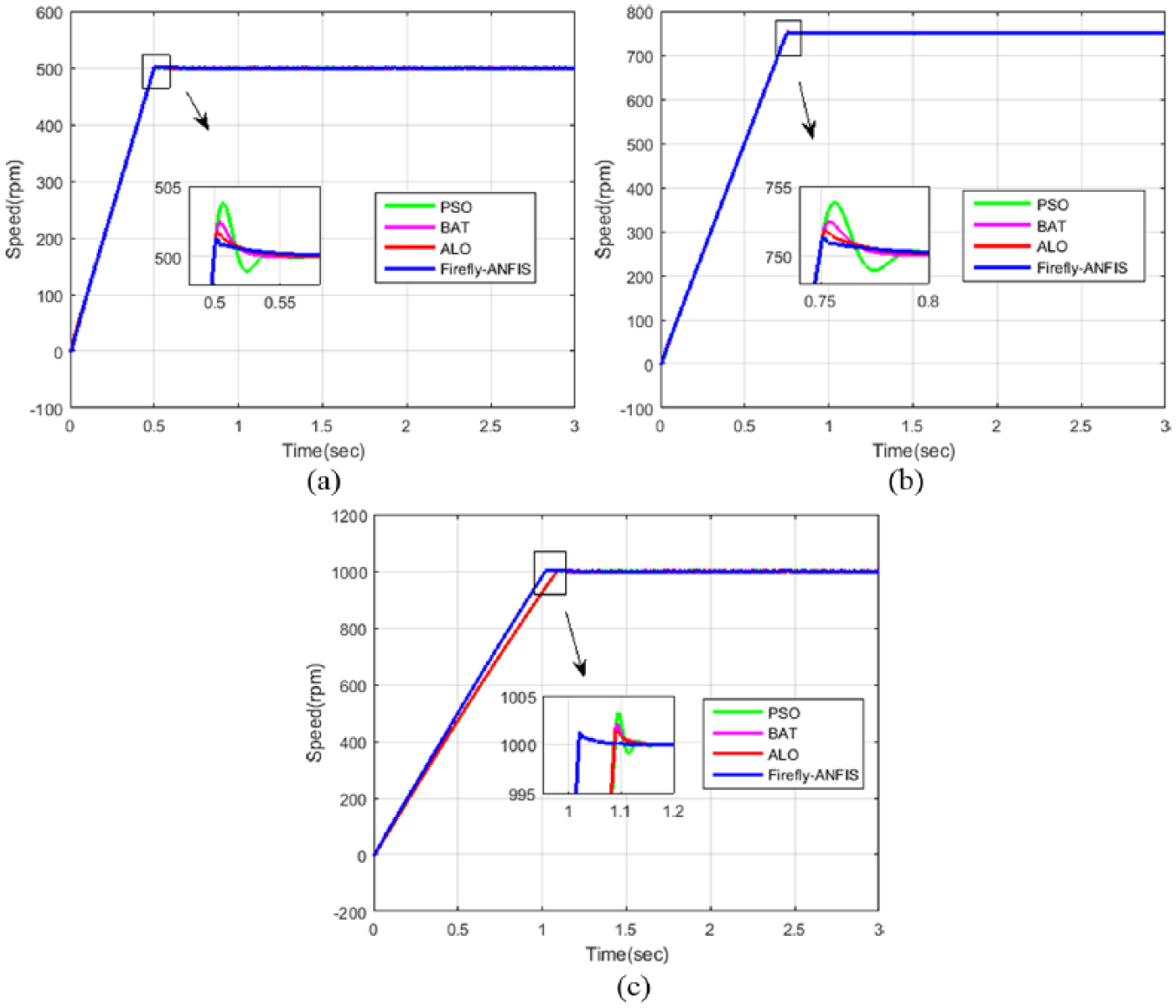
The comparison analysis of speed in (a) case 1, (b) case 2 and (c) case 3.
Table 2 shows the summary about the reduction of torque ripples under the speed variations using three case conditions. Initially, the operating speed is considered as 500 r/min; various methods such as BA, PSO algorithm, ALO algorithm and proposed algorithm are analyzed to reduce the torque ripple. Here, the proposed algorithm is utilized to improve the torque deviation that is compared with BA, PSO algorithm and ALO algorithm such as 4.9%, 6.75% and 3.12%. And, the speed is considered 750 r/min; also, the proposed technique improved the torque deviation compared with the other methods like BA (2.25%), PSO (2.48%) and ALO (1.98%). Similarly, the speed is consider as 1000 r/min; the percentage of the torque ripple is reduced in proposed method as compared with existing techniques is 0.79%, 2.69% and 0.42%. From the analysis and the comparison, the effectiveness of the proposed system is better than the other existing techniques like PSO, ALO and BA. In this respect, the proposed technique is utilized to minimize the torque ripples of the BLDC motor. However, the existing methods have analyzed to reduce the torque ripples and provide the superiority over the proposed methods from computation complexity parameter tuning point of view. In conclusion, the projected control system improves robustness and accurateness of the drive scheme at the outflow of more computational complexity and correcting some more supplementary parameters associated with conventional approaches.
Analysis the speed variations under the reduction of torque ripple.
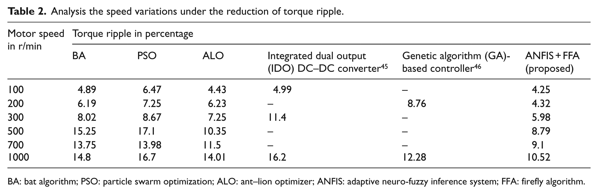
BA: bat algorithm; PSO: particle swarm optimization; ALO: ant–lion optimizer; ANFIS: adaptive neuro-fuzzy inference system; FFA: firefly algorithm.
Conclusion
Hence, an improved FOPID controller is presented for controlling the speed and reducing the torque ripple of BLDC motor system. The proposed controller is based on the FFA-based ANFIS technique, and it is implemented in MATLAB/Simulink platform. The gain parameters of FOPID are tuned using proposed technique, which provides the optimal control signal. Here, the speed, torque, current and back EMF performance of the BLDC motor using proposed technique is determined. The performance of proposed controller was compared with existing techniques like ALO algorithm, BA and PSO algorithm–based FOPID controller. The effectiveness of the proposed controller was analyzed; from the analysis, the rise time, settling time and overshoot time are analyzed. Moreover, the torque ripples are determined using the proposed FOPID and existing method–based FOPID controllers, respectively. The setting time and overshoot time are reduced and the stability of the system is thus maintained effectively by proposed controller. From the performance analysis, the simulation outcome of the proposed model shows better performance than that of the existing methods.
Footnotes
Declaration of conflicting interests
The author(s) declared no potential conflicts of interest with respect to the research, authorship, and/or publication of this article.
Funding
The author(s) received no financial support for the research, authorship, and/or publication of this article.