
Abstract
Background:
Parameters of the hydroelectric power plant controllers are typically tuned at the nominal operating conditions such as nominal head and single unit operation. Water level variations in reservoir and/or tailwater, and the presence of other active units sharing the penstock are common disturbances to the nominal assumption.
Methods:
This article proposes two adaptive add-ons, namely gain scheduling and model reference adaptive control, to the existing speed controllers to improve grid synchronization performance when the site conditions are not nominal. The add-ons were designed and tested on a validated dynamic model of a power plant unit by using a software-in-the-loop simulation setup. An off-season scenario is simulated, in which the original controller of the unit cannot bring the turbine to synchronize with the grid due to low gross head. Then, the add-ons were implemented on-site and experiments were performed under similar conditions. The parameter sets used in gain scheduling for different operation bands are determined off-line with the help of operational experience. The model reference adaptive control add-on requires a reference model and a learning rate. A description of the turbine speed-up profile at nominal operating conditions is sufficient to be used as the reference model. The proposed piecewise linear reference model favors stability over speed in settling to the nominal speed.
Results:
It is experimentally shown that the proposed add-ons compensate the negative effect of head loss in grid synchronization, and perform similar to the ideal performance at the nominal head.
Conclusion:
Both add-ons can be implemented on the available off-the-shelf speed governor controllers. They are suitable for use in all hydroelectric power plants, especially in unmanned ones, for automatic synchronization with less waste water.
Keywords
Introduction
A general layout of a hydroelectric power plant (HEPP) is depicted in Figure 1. Water travels from a reservoir, through tunnel and penstock, to turbine and discharges to tailwater. Except isolated operation, a generating unit is in one of the three modes, namely, standstill, synchronization, and generation. When the unit is started, the speed governor adjusts the turbine speed from standstill to nominal speed to synchronize with the corresponding electrical frequency of the network.
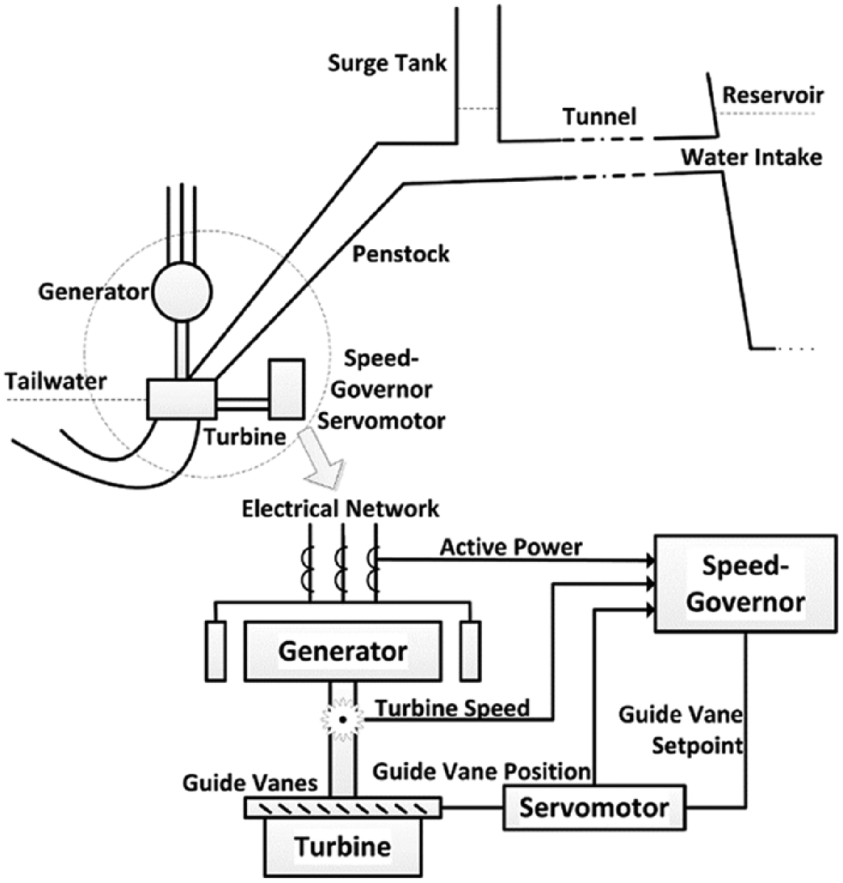
General layout of an HEPP.
Parameters of the speed-governor controller are typically tuned at the nominal operating conditions such as nominal head and single unit operation. Water-level variations in reservoir and/or tailwater and the presence of other active units sharing the penstock are common disturbances to the nominal assumption. They could cause drastic errors in speed control and diminish the synchronization performance of speed governors. The latency in network synchronization not only prevents the power plant to reach day-ahead generation targets which are committed per hour but also wastes turbined water without active power.
The current state-of-the-art for hydraulic turbine control is digital governors, mostly proportional–integral (PI) controllers and some with modern control techniques. 1 On the classical control side, PI control stability issues2,3 and various techniques for determination of PI parameters4–7 are studied by the majority. On the modern control side, studies cover nonlinear, optimal, and robust control through state variable representation. A self-tuning power system stabilizer, which uses minimization of the quadratic performance index, is presented in Lim. 8 A genetic algorithm is used in Lansberry et al. 9 to optimize speed-governor performance of an HEPP. Speed-governor designs with neural networks are explained in Padrón et al. 10 for an isolated power system, and in Venayagamoorthy et al. 11 by the implementation of neurocontrollers. Robust control of hydraulic turbines through frequency–response technique is presented in Natarajan. 12
When the parameters of the plant are unknown or change in time, adaptive control maintains the control system performance at a desired level by automatic adjustment of controllers in real time.13,14 Gain scheduling (GS) control is an adaptive approach utilizing a look-up table. The controller parameters are automatically picked from the look-up table according to the active operating point, which is determined via an auxiliary measurement. 14 For each operating point or band, the parameters are predetermined. GS is used for both active power and speed control of a hydroelectric unit with leaky guide vanes in Doan and Natarajan, 15 where the parameters of the controller are changed to control a secondary water input. In Ruzhekov et al., 16 GS is compared with the conventional PI controllers in active power control under different load conditions. The advantages of the adaptive approach are shown based on simulations on a nonlinear HEPP model. Model reference adaptive control (MRAC) aims to improve the closed-loop performance of a plant based on the output of a reference model, which describes the desired behavior of the plant. 13 One of the earlier HEPP applications is reported in Vogt et al., 17 where the parameters of a gate position to pressure model is identified based on a reference model. Multiple reference models, depending on load, are used in Puleva and Ichtev 18 for both active power and speed control of a hydroelectric unit.
In practice, most of the speed governors are based on classical PI control. This article investigates adaptive add-ons to improve the performance of the existing PI controllers. The proposed GS and MRAC add-ons are simple enough to be implemented into the existing hardware (i.e. Programmable Logic Controllers PLCs) yet effective to enable network synchronization when the site conditions are not nominal.
A software-in-the-loop (SIL) simulation setup is constructed to develop and test the add-ons. SIL tests are crucial because they allow thorough investigation and debugging of the controller code before implementation. Failure or unexpected behavior of the controller on-site causes plant outages and may also lead to serious accidents. The SIL setup is composed of a simulation platform, a code development platform, and a data exchange interface. The simulation platform includes a detailed dynamic HEPP model. The code development platform is for writing and testing the controller code to be implemented on the real plant. Data exchange interface transfers relevant signals between two platforms.
After SIL simulations, the add-ons were implemented in a single unit of Gezende HEPP during off-season, when the head is lower than the nominal value. The site tests confirm that the proposed add-ons compensate the negative effect of head loss in grid synchronization.
The rest of the article is organized as follows: The SIL setup, along with modeling, implementation, and validation of the dynamic HEPP model, is explained in the “SIL simulation setup” section. “GS add-on” and “MRAC add-on” sections provide details of the proposed GS and MRAC add-ons, respectively. The results of simulations and site tests are discussed in the “Results and discussion” section, and the “Conclusion” section concludes the article.
SIL simulation setup
SIL simulation setup is for the design and tests of controller codes on validated dynamic HEPP models. In practice, controller codes are usually developed on-site, since the simulations cannot completely reflect the real site conditions. On the other hand, a validated dynamic model through site measurements is sufficient for testing the main safety and control actions.
The overview of the SIL setup is shown in Figure 2. The simulation platform contains the mathematical model of the HEPP unit. The code development platform emulates the speed-governor controller. It provides coding tools for the specific industrial control hardware of the speed governor so that the final version of the control code can be directly implemented on-site. Signal interaction between the platforms is achieved through a data exchange interface.
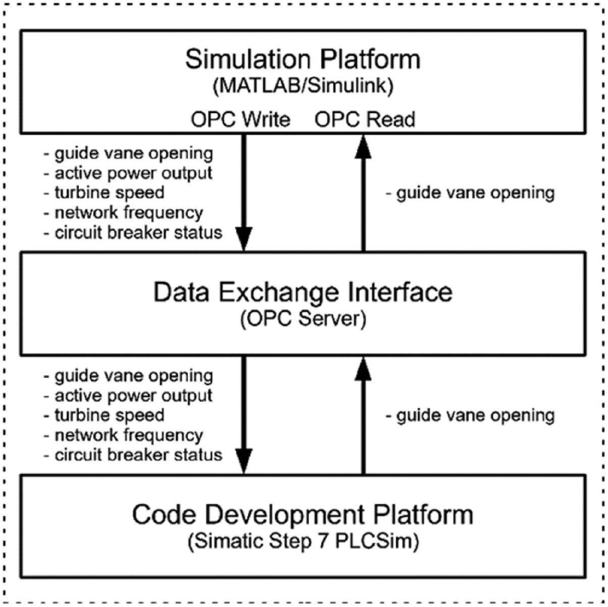
Overview of the software-in-the-loop simulation setup.
HEPP model
Controller design for significant changes in active power output and turbine speed of the unit requires nonlinear models, 19 which include frictions and hydraulic pressure oscillations. 20 Since the focus of the study is on the network synchronization of the unit, meaning that the turbine speed changes from standstill to nominal speed, the nonlinear HEPP model in Figure 3 is constructed in MATLAB/Simulink. The electromagnetic dynamics of the generator are not considered because of its very short time constant compared to that of hydrodynamics. 21 Calculation of the model parameters and derivation of the differential equations are explained in previous works22–24 and summarized in Supplementary Appendix I.
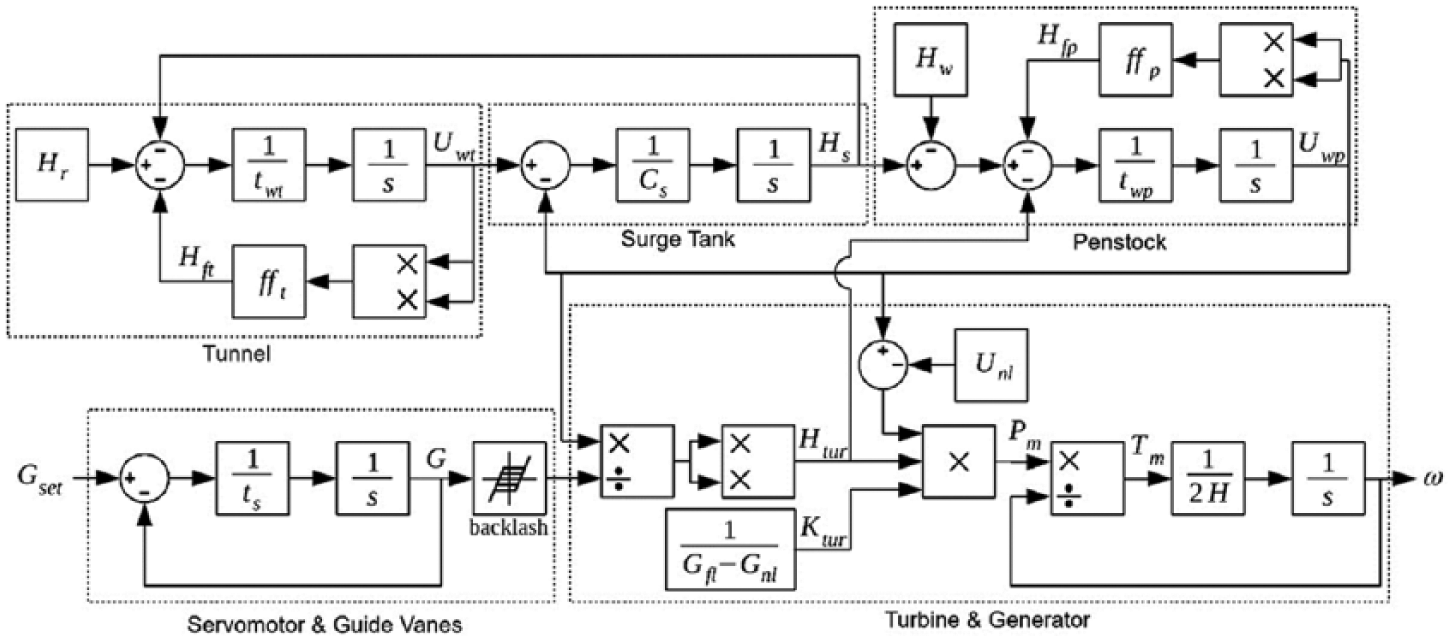
Generic model of an HEPP unit.
The controllers designed in this study are experimented on a single unit of Gezende HEPP. Gezende is an old plant with three vertical Francis turbines of 53 MW installed capacity each. Its characteristic parameters (Table 1) are applied to the model with the following two assumptions:
Characteristic parameters of Gezende HEPP.
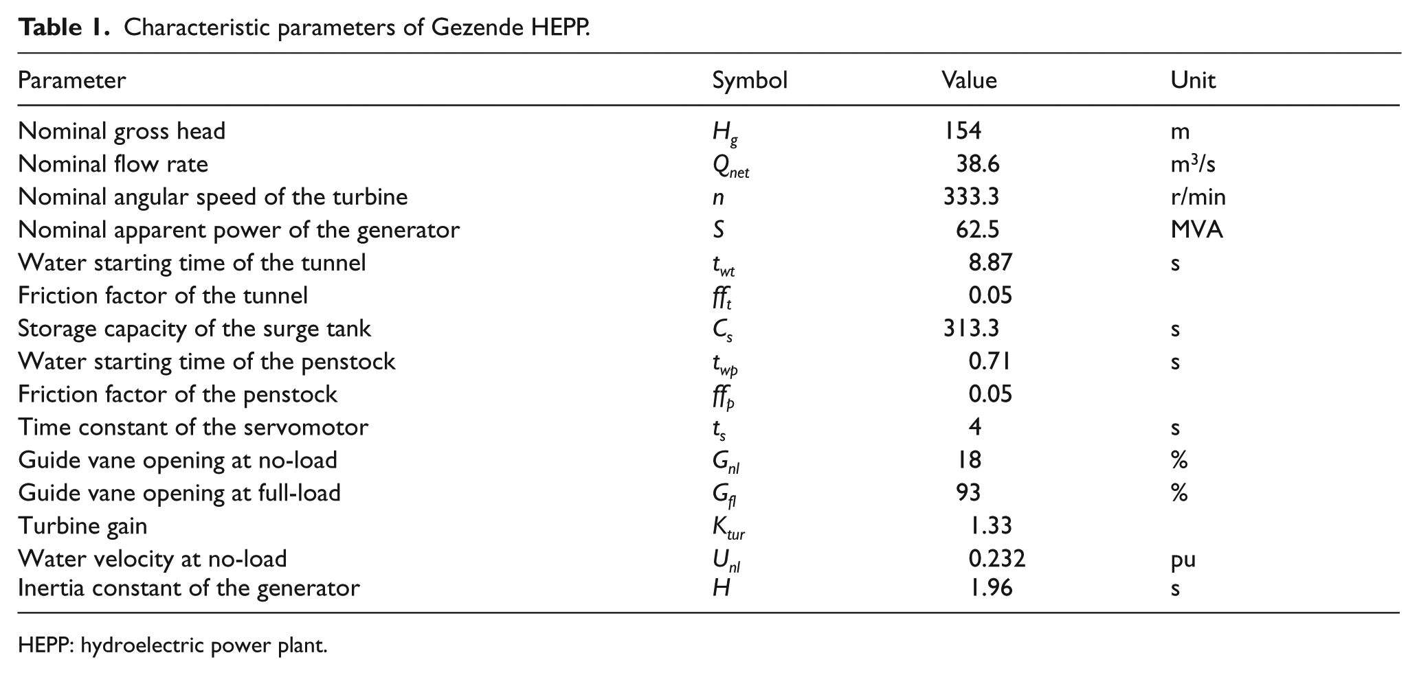
HEPP: hydroelectric power plant.
Gezende HEPP has a short-medium penstock and a surge tank; hence, wave propagation is not considered (i.e. Hw = 0).
Rotating inertia of the turbine is approximately 5% of the generator rotating inertia, 23 so that rotating inertia of the unit dominantly depends on the generator characteristic, H.
Speed-governor controller
The speed governor regulates the amount of water entering the turbine by controlling the guide vane opening. For network synchronization, the reference input is the electrical grid frequency (ωset), and the feedback is the turbine speed (ω). The speed governor of Gezende HEPP is implemented in a Siemens SIMATIC S7 controller, and it utilizes both open-loop and closed-loop modes for speed control, as shown in Figure 4.
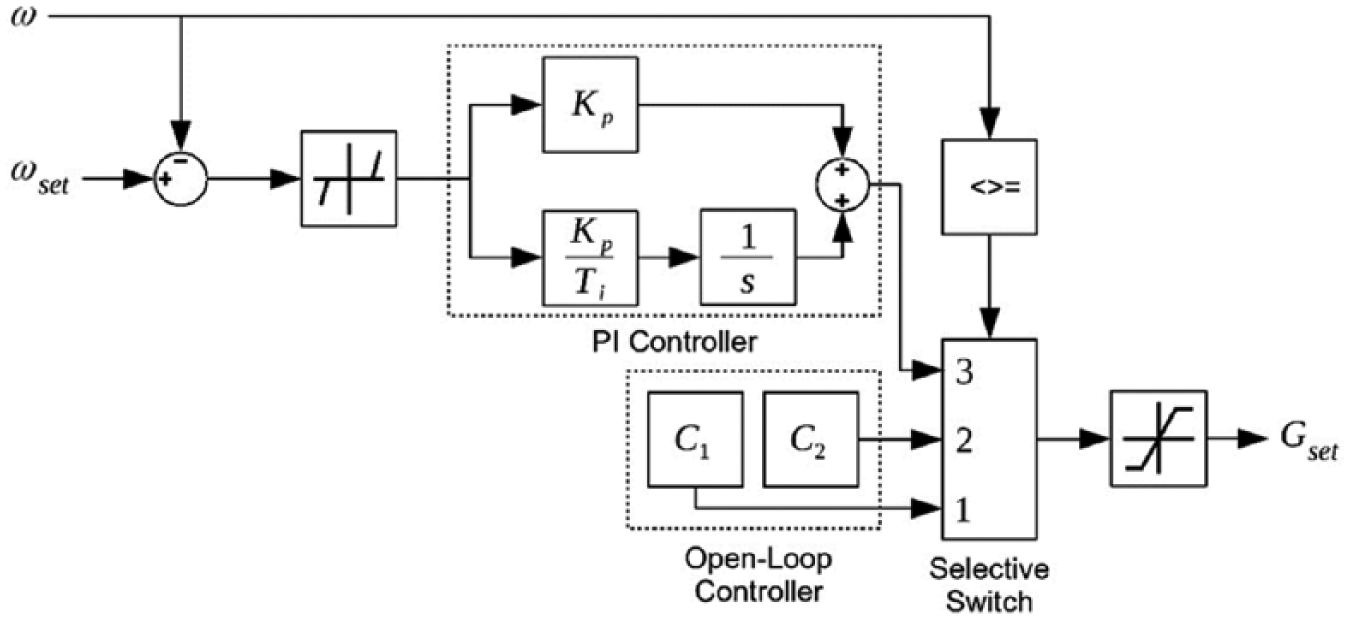
Turbine speed controller of Gezende HEPP.
At the nominal head, the guide vanes are opened first up to C1 = 25%, until turbine speed reaches 300 r/min (0.9 pu), then the opening is decreased to C2 = 19%, until turbine speed reaches to 317 r/min (0.95 pu). After this point, the closed-loop PI controller takes over. The deadband for the speed error is intentional to provide stable operation by preventing oscillations in the guide vane opening. Likewise, the saturation for the guide vane opening setpoint (Gset) is a safety measure.
Model validation
The dynamic model is validated by comparison with the site measurements. Turbine speed of a single unit of Gezende HEPP was increased from standstill to nominal speed (i.e. speed-up), then decreased back to standstill (i.e. shut-down). Turbine speed and guide vane opening values were recorded at every 0.5 s. During the measurements, the head was at the nominal range and one of the neighbor units was active. Then, the measured guide vane opening values were given as time-based workspace input to the MATLAB/Simulink model (Figure 3). Figure 5 shows the measured and simulated turbine speeds for the same guide vane openings. The simulation results correspond to the measurements with 0.89% average error and 2.1% maximum error during speed-up, and 0.97% average error and 1.6% maximum error during shut-down.
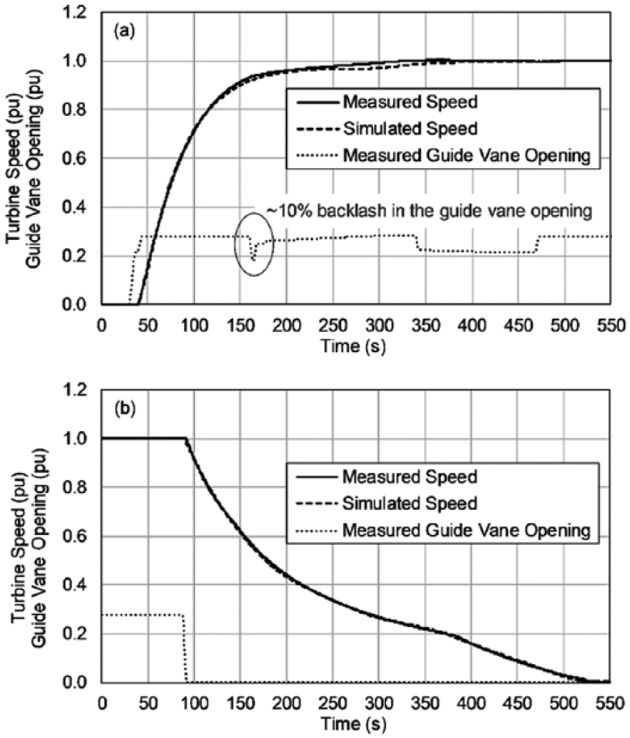
Measured and simulated turbine speed (Hg = 1 pu, N = 1): (a) speed-up and (b) shut-down.
As a special note, the presence of backlash in the guide vane mechanism has a negative effect on regulation. This effect is especially significant in old plants. As seen in Figure 5(a), although the guide vane opening is decreased by 10% at t = 165 s, the turbine speed is not affected. The backlash is handled by a feedforward controller, which adds the amount of backlash to the guide vane setpoint as the direction changes from opening to closing and vice versa. 25 The second guide vane dip in Figure 5(a) is a result of this control action.
GS add-on
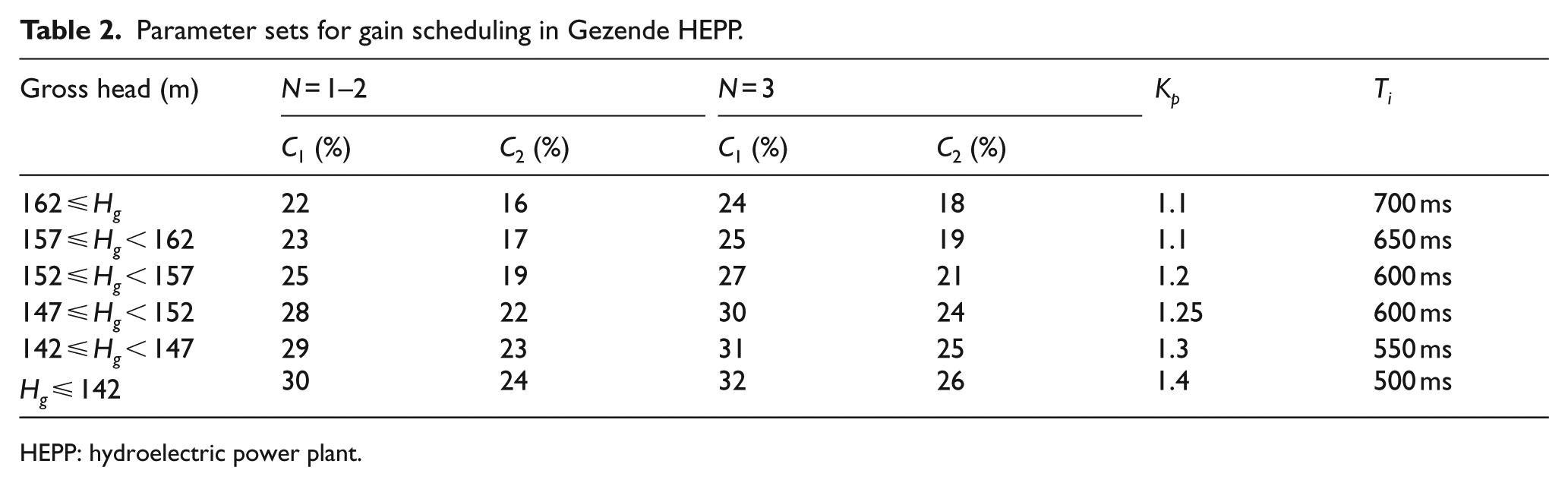
Turbine speed controller with GS add-on is shown in Figure 6. The gain scheduler reads the gross head value (Hg) from auxiliary sensors and the number of active units (N) from the top-level controller. It then changes the parameters of the open-loop and closed-loop controllers corresponding to the active operating band (Table 2). The parameters for Gezende HEPP are determined empirically over the years by experienced site operators, and they have been applied manually based on seasonal head measurements.
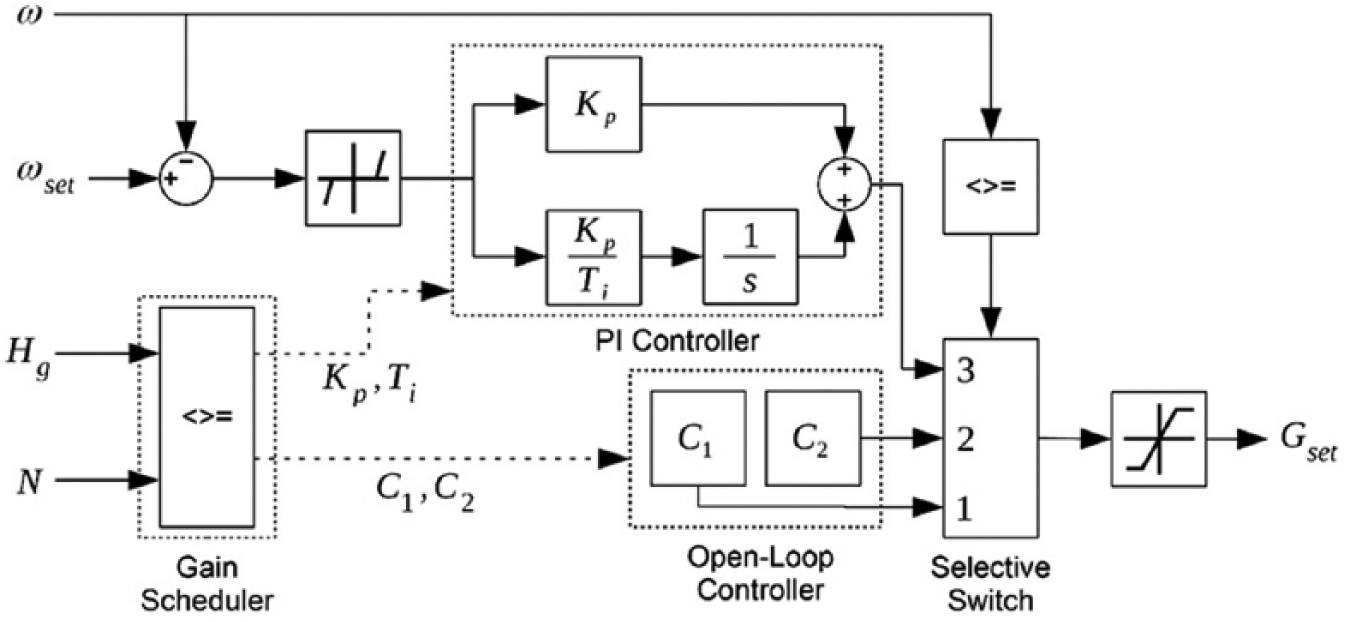
Turbine speed controller with gain scheduling.
Parameter sets for gain scheduling in Gezende HEPP.
HEPP: hydroelectric power plant.
MRAC add-on
Turbine speed controller with MRAC add-on is shown in Figure 7. The MRAC design is explained in Supplementary Appendix II. The reference model outputs the desired turbine speed. This value is multiplied with the error between the desired and actual speeds, and given as input to the adaptation mechanism. The product is multiplied with the learning rate, Γ, and integrated to produce the coefficient, θ, which manipulates the output of the main controller. It is quicker to achieve the desired behavior by using a larger Γ, but after a critical value, the controller becomes unstable. The output of the MRAC add-on effectively amplifies the gains C1, C2, and Kp, which are set to their nominal (i.e. Hg = 154 m) values. Since Gezende HEPP is an old plant, the stable range of controller parameters is known from experience (see Table 2). Therefore, θ value is confined between 0.9 and 1.1 by using a saturation block to ensure stability. If the plant were a new project, the stability margin could be found by using the technique presented in Vournas and Papaioannou. 26
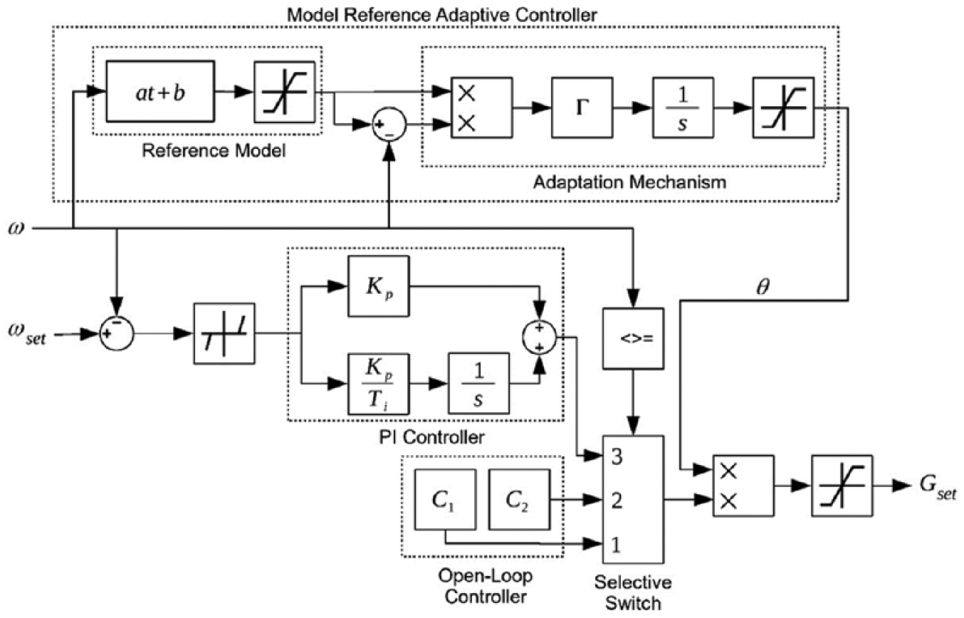
Turbine speed controller with MRAC.
Reference model for speed control
The desired turbine speed profile is split into eight zones, as shown in Figure 8, and a time-based piecewise linear reference model in Table 3 is constructed. The same profile can also be approximated by using a first-order transfer function as the reference model; however, the proposed approach provides more flexibility in shaping the desired behavior.
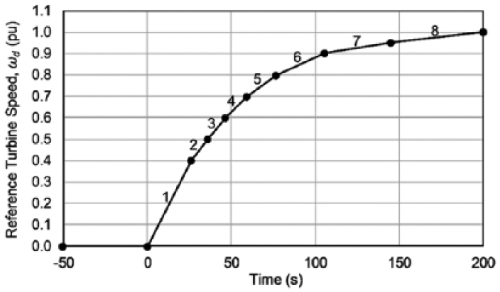
Desired turbine speed profile.
Reference model for turbine speed.
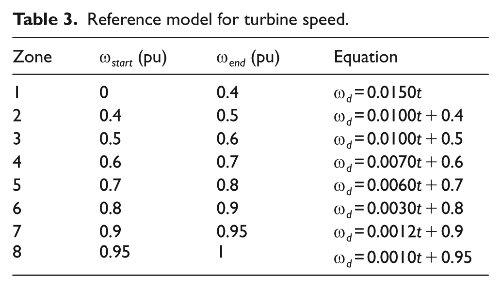
Switching from one zone to the next is determined by the actual turbine speed. At each zone, the reference model outputs the desired speed, ωd, from the corresponding equation, where the variable t represents the time spent in that zone.
Results and discussion
Figure 9(a) shows the performance comparison of controllers based on the SIL simulations with single unit operation (N = 1) at 0.9 pu gross head. Without the add-ons, the main controller starts in the open-loop mode with C1 = 25%, as it would at the nominal head. The thresholds for switching to C2 and closed-loop mode are not met because of the head loss; hence, the turbine speed settles at 0.81 pu and fails to synchronize with the network. With the GS add-on, the main controller operates with C1 = 30%, C2 = 24%, Kp = 1.4, and Ti = 400 ms, according to Table 2. The response settles smoothly to the nominal speed. This is an expected result since the parameter sets are obtained empirically from the site.
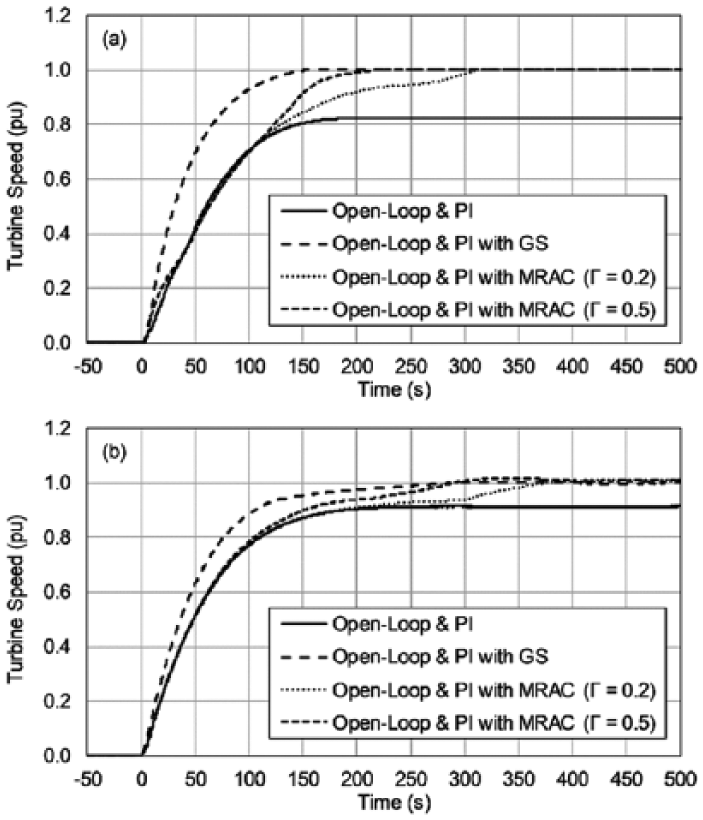
Performance comparison of controllers: (a) simulation (Hg = 0.9 pu, N = 1) and (b) site tests (Hg = 0.95 pu, N = 2).
Simulations with the MRAC add-on started with Γ = 0.2. The learning rate is increased until the settling time of the GS add-on is matched with Γ = 0.5. Responses follow that of the main controller until it starts to deviate from the desired behavior. They then adapt to the response of the reference model and settle to the nominal speed. Mode switching of the main controller at 0.9 and 0.95 pu turbine speed is especially visible in the Γ = 0.2 case.
The simulated controllers are implemented on-site, and the results are shown in Figure 9(b). During the tests, the gross head was 0.95 pu, and one of the other two units was also active (N = 2). The main controller, by itself, fails again to reach the nominal speed. The C2 threshold is met; however, this reduced the already insufficient guide vane opening to 19% and the speed remained at 91 pu. The GS add-on and the MRAC add-on with Γ = 0.5 were able to settle to the nominal speed in 280 s, and the MRAC add-on with Γ = 0.2 is 100 s slower.
Results of the site tests with the MRAC add-on are plotted in Figure 10 alongside the corresponding reference model outputs and θ values. With Γ = 0.2, θ increases slowly and reaches a maximum value of 1.034. The increase is visible in Figure 10(a) from zone 5 onward (i.e. after 80 s). The higher learning rate causes faster increase in θ and results in a shorter settling time. The maximum value of θ is 1.064, which is below the saturation threshold of 1.1.
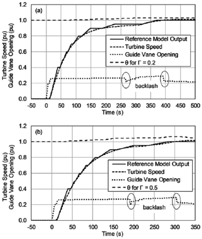
Site test results with MRAC add-on (Hg = 0.95 pu, N = 2): (a) Γ = 0.2 and (b) Γ = 0.5.
The proposed reference model does not have an absolute time dependency; instead, it is designed for smoothly guiding the turbine to the nominal speed. This is especially important for grid synchronization. Since there is no active power output, turbine speed can overshoot rapidly if the guide vanes are opened more than necessary. If the reference behavior were fixed in the time axis (e.g. first-order response), then the accumulating error, especially in the low-head cases, would rapidly increase θ. If this type of reference model is to be used, the intentional saturation in the adaptation mechanism is a safeguard against instability.
Conclusion
Two adaptive add-ons were presented and compared for the grid synchronization of hydraulic turbines. The attractive feature of the proposed add-ons is that they can easily be implemented alongside the existing controllers in the speed governor and aid them when the site conditions are not nominal. A generic dynamic model of an HEPP unit is presented and validated by using experiments on Gezende HEPP site under nominal conditions. Then, this model is used in a SIL setup for controller design and testing before site implementation. A worst-case off-season scenario with 0.9 pu gross head is simulated, in which the original controller of the unit cannot bring the turbine to synchronize with the grid. Once the add-ons were designed via simulations, site experiments were also performed under nonnominal conditions for experimental validation.
The GS add-on is essentially the automatic selection of controller parameters that are proven to be successful over the years. The used parameter sets have been applied manually by the site operators depending on-site conditions. Their validity was also confirmed in this study. However, this method requires knowledge of the entire possible operating range to maintain a desirable controller performance at all times. If this range is wide, more design and implementation effort is required, since it might be necessary to tune the parameters on-site. Once the gain table is built, however, GS provides rapid action against variations.
The MRAC add-on requires a reference model, describing the behavior only at nominal conditions, and a learning rate. The measured turbine speed for model validation is also used for the design of the reference model. The proposed piecewise linear reference model favors stability over speed in settling to the nominal speed. It is experimentally shown that the MRAC add-on with Γ = 0.5 compensates the negative effect of head loss at Hg = 0.95, and performs similar to the original controller at the nominal head. Despite being slower, the turbine speed also settled successfully to the nominal value by using a lower learning rate of Γ = 0.2.
Both add-ons can be implemented on the available off-the-shelf speed-governor controllers. They are suitable for use in all HEPPs but especially in unmanned plants for automatic synchronization with less wastewater. To compare the two approaches, the GS add-on is a simpler design requiring a head-level sensor and a look-up table. It can be implemented in old plants without modeling and simulation effort, since the gain sets are available from experience. On the other hand, if incorrect scheduling occurs, due to head measurement failure or unforeseen changes in plant dynamics, there is no internal feedback for compensation. Design of the MRAC add-on requires a description of the desired nominal behavior, which requires moderate modeling effort not only for new projects but also for old plants. Simulations may be useful to ensure stability and performance, especially for the new projects. Once designed, plant is led to desired operation in closed loop regardless of the plant condition, without an auxiliary measurement. The MRAC add-on can be improved to cover active power control and frequency control loops as future work, along with detailed cost/benefit analyses in design and implementation.
Supplemental Material
MAC_Appendix – Supplemental material for Speed control of hydraulic turbines for grid synchronization using simple adaptive add-ons
Supplemental material, MAC_Appendix for Speed control of hydraulic turbines for grid synchronization using simple adaptive add-ons by Dogan Gezer, Yiğit Taşcıoğlu and Kutay Çelebioğlu in Measurement and Control
Footnotes
Declaration of conflicting interests
The author(s) declared no potential conflicts of interest with respect to the research, authorship, and/or publication of this article.
Funding
This research is supported by the project “Gezende HEPP Rehabilitation Project” numbered 5112802 and conducted at TUBITAK (Scientific and Technological Research Council of Turkey), Marmara Research Center (MRC) Energy Institute. The authors would like to kindly thank TUBITAK MRC.
References
Supplementary Material
Please find the following supplemental material available below.
For Open Access articles published under a Creative Commons License, all supplemental material carries the same license as the article it is associated with.
For non-Open Access articles published, all supplemental material carries a non-exclusive license, and permission requests for re-use of supplemental material or any part of supplemental material shall be sent directly to the copyright owner as specified in the copyright notice associated with the article.