
Abstract
This paper reports on the application of infrared external reflection spectroscopy (IR-ERS) to the characterization of small surface area addresses prepared on smooth gold surfaces after modification for use as capture substrates in sandwich immunoassays based on surface-enhanced Raman scattering (SERS). Most of the past work with IR-ERS on analyzing coatings formed on highly reflective metals utilized relatively large area samples (e.g., 76 × 25 mm glass microscope slides and ∼51 mm diameter silicon wafers) to accommodate the large size of the elliptical IR beam reflected off the metal surface at grazing angles of incidence. Our interest in employing assay-sized (3 mm diameter) addresses for IR-ERS measurements arises from the need to minimize the consumption, and, thereby, the expense of rare biological reagents like the antibodies under development for immunoassays to detect tuberculosis. The obvious approach to achieving this goal would be to utilize the spatial resolution and sample scanning capabilities of Fourier transform infrared (FT-IR) microscopes. We, however, opted to re-examine the physical optics and geometric layout of the measurement through an analysis of the strength of the mean square electric field at the sample/substrate interface as a function of angle of incidence. These findings suggested that, given the high light throughput and low noise levels of today’s FT-IR spectrometers, it may be possible to perform these measurements simply by collecting spectra at a lower angle of incidence when using the optical layout of a standard IR-ERS experiment. Herein, we report both the theoretical analysis and experimental results that demonstrate it is possible to obtain useful spectra from much smaller samples than those traditionally used, e.g., those employed in our SERS-based immunoassays, simply by decreasing the angle at which the IR beam is incident on the sample surface. We also demonstrate that these types of samples can be analyzed by constructing a small jig that allows for the careful positioning of the sample in the IR beam, rather than by extensively modifying the optics of the IR-ERS accessory.
This is a visual representation of the abstract.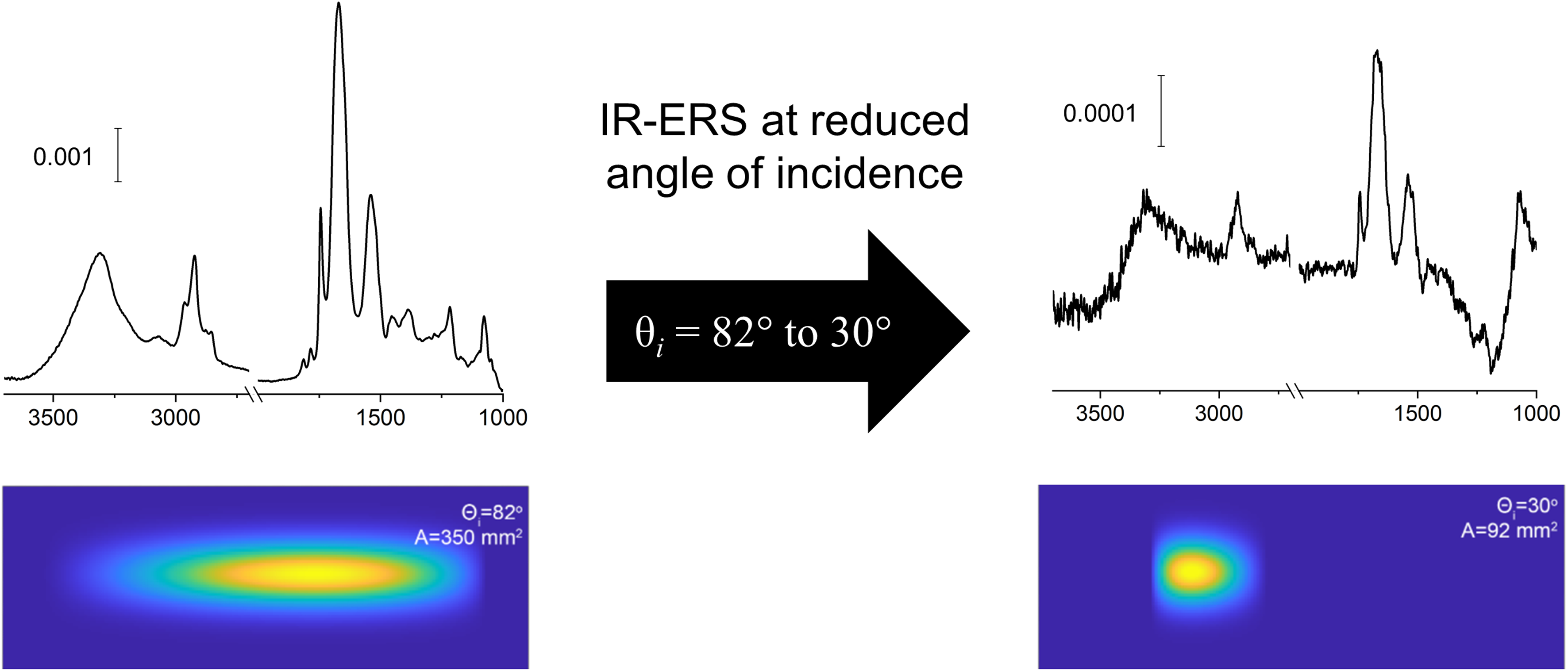
Keywords
Get full access to this article
View all access options for this article.
References
Supplementary Material
Please find the following supplemental material available below.
For Open Access articles published under a Creative Commons License, all supplemental material carries the same license as the article it is associated with.
For non-Open Access articles published, all supplemental material carries a non-exclusive license, and permission requests for re-use of supplemental material or any part of supplemental material shall be sent directly to the copyright owner as specified in the copyright notice associated with the article.