
Abstract
There is a synergistic relationship between analog field testing and the deep space telecommunication capabilities necessary for future human exploration. The BASALT (Biologic Analog Science Associated with Lava Terrains) research project developed and implemented a telecommunications architecture that serves as a high-fidelity analog of future telecommunication capabilities for Mars. This paper presents the architecture and its constituent elements. The rationale for the various protocols and radio frequency (RF) link types required to enable an interdisciplinary field mission are discussed, and the performance results from the BASALT field tests are provided. Extravehicular Informatics Backpacks (EVIB) designed for BASALT and tested by human subjects are also discussed, and the proceeding sections show how these prototype extravehicular activity (EVA) information systems can augment future human exploration. The paper concludes with an aggregate analysis of the data product types and data volumes generated, transferred, and utilized by the ground team and explorers over the course of the field deployments.
1. Introduction
The BASALT (Biologic Analog Science Associated with Lava Terrains) research program includes a unique mix of scientists, engineers, and experts from both human spaceflight mission operations and deep space robotic exploration, working together to meet a variety of research objectives. The team worked collaboratively to explore and conduct planetary science research at two terrestrial volcanic environments that have scientific analog applications to understanding the habitability potential of Mars (Hughes et al., 2018; Lim et al., 2019). The In-Field (in the field) scientific activities of the BASALT program were performed In-Sim (in simulation) (Lim et al., 2019), that is, under simulated Mars mission conditions, which included Mars-to-Earth telecommunication latencies and bandwidth limitations. The simulation infrastructure included a telecommunication architecture that supported data relay and exchange with various members of the flight team, and included components such as a backpack equipped with a modern suite of candidate EVA (extravehicular activity) informatics systems, as well as scientific hand tools for Mars surface exploration (Fig. 1).
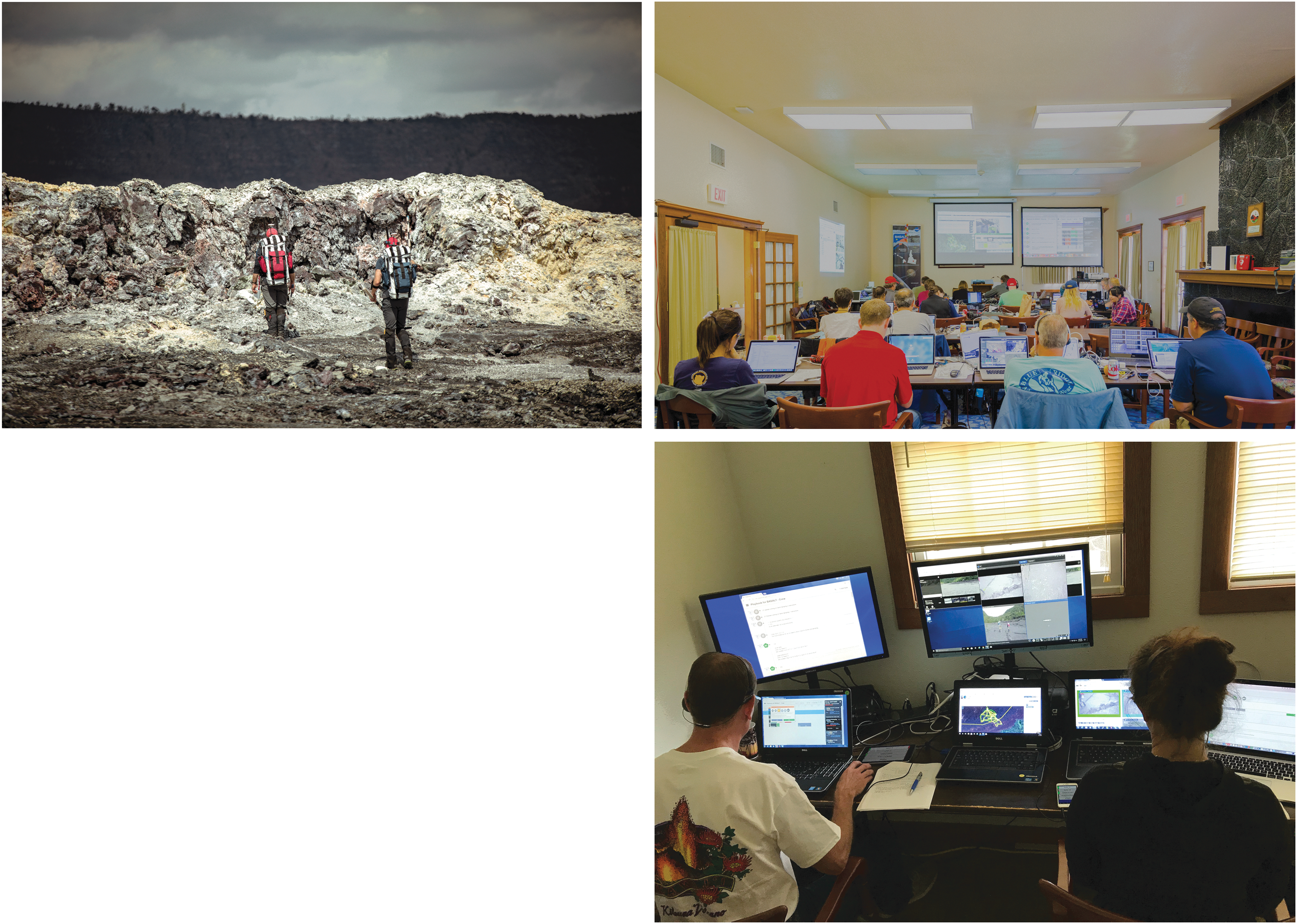
(
Under In-Sim constraints, the In-Field activities of the BASALT program were focused on the “boots on the ground,” or Intra-EVA, phase of exploration, specifically the process of scientific reconnaissance and discovery during an EVA akin to Mars surface operations (Beaton et al., 2019a). The network performance data collected during BASALT field test operations provides a flightlike representation of the communications utilization of martian scientific EVA operations. These data were comprised of bandwidth measurements of all BASALT field elements (extravehicular [EV] and intravehicular [IV] crew member communications, Extravehicular Informatics Backpacks [EVIB], and science instruments) throughout the telecommunications infrastructure.
Extravehicular crew members were located in the field executing science exploration and sampling tasks. Intravehicular crew members, located in the simulated rover or habitat, guided the EV crew members and communicated with the Earth-side Mission Support Center (MSC) (Beaton et al. 2019a; Lim et al., 2019). For the BASALT simulations, IV crew members were located in an isolated room of the MSC and operated on “Mars time.” Section 2.2 of this paper outlines the mission elements that are included and excluded in the BASALT infrastructure and subsequent bandwidth utilization data. These data have important implications for the establishment of telecommunication requirements necessary to enable similar future human scientific exploration missions.
This paper describes the telecommunication architecture setup and the individual hardware components that were required to establish the BASALT telecommunications infrastructure. A brief derivation of the BASALT architecture is provided, as well as a description of the process of architecture implementation, operation, and data analytics. For a more detailed account of the history and applications of analog field tests with regard to the development of a telecommunication architecture for future human and robotic spaceflight, see the work of the companion paper by Seibert et al. (2019). Finally, this paper presents a utilization analysis of the BASALT telecommunication infrastructure for the BASALT-1 (Idaho 2016) and BASALT-2 (Hawai‘i 2016) field deployments (described in Lim et al., 2019) and summarizes the data demands imposed on the architecture.
1.1. Brief background: Prior telecommunication test beds that influenced the BASALT infrastructure
The National Aeronautics and Space Administration (NASA), the United States Geological Survey (USGS), various space agencies in the International Space Exploration Coordination Group, and a variety of nongovernmental organizations (industry, academic organizations) have been performing field test experiments and analogs as early as the Mercury program (Schaber, 2005; Seibert et al., 2019). These field-based deployments have provided a low-risk, high-research-return environment within which to test proposed scientific, operational, and technical elements associated with future human and robotic spaceflight architectures.
In the late 1960s and early 1970s, Apollo crew members, engineers, scientists, and other support personnel, as shown in Fig. 2, traveled to as many as 17 geologically analogous locations around the globe to evaluate systems, tools, and techniques to prepare for lunar surface mission operations. In 1997, NASA's Human Exploration and Operations Mission Directorate began funding a team of NASA engineers, led by engineers who had worked on the Apollo Program, to pick up where Apollo left off in testing systems in the field. At that time, the NASA Desert Research and Technology Studies (DRATS) team began testing systems and techniques in locations with terrain analogous to the Moon, starting with one pressurized spacesuit and one robotic assistant. Astronauts and scientists joined the engineering teams to design and conduct the field experiments, and in 2004 the team deployed a telecommunications infrastructure that was a high-fidelity analog to future lunar concepts (see Seibert et al., 2019, for further details).
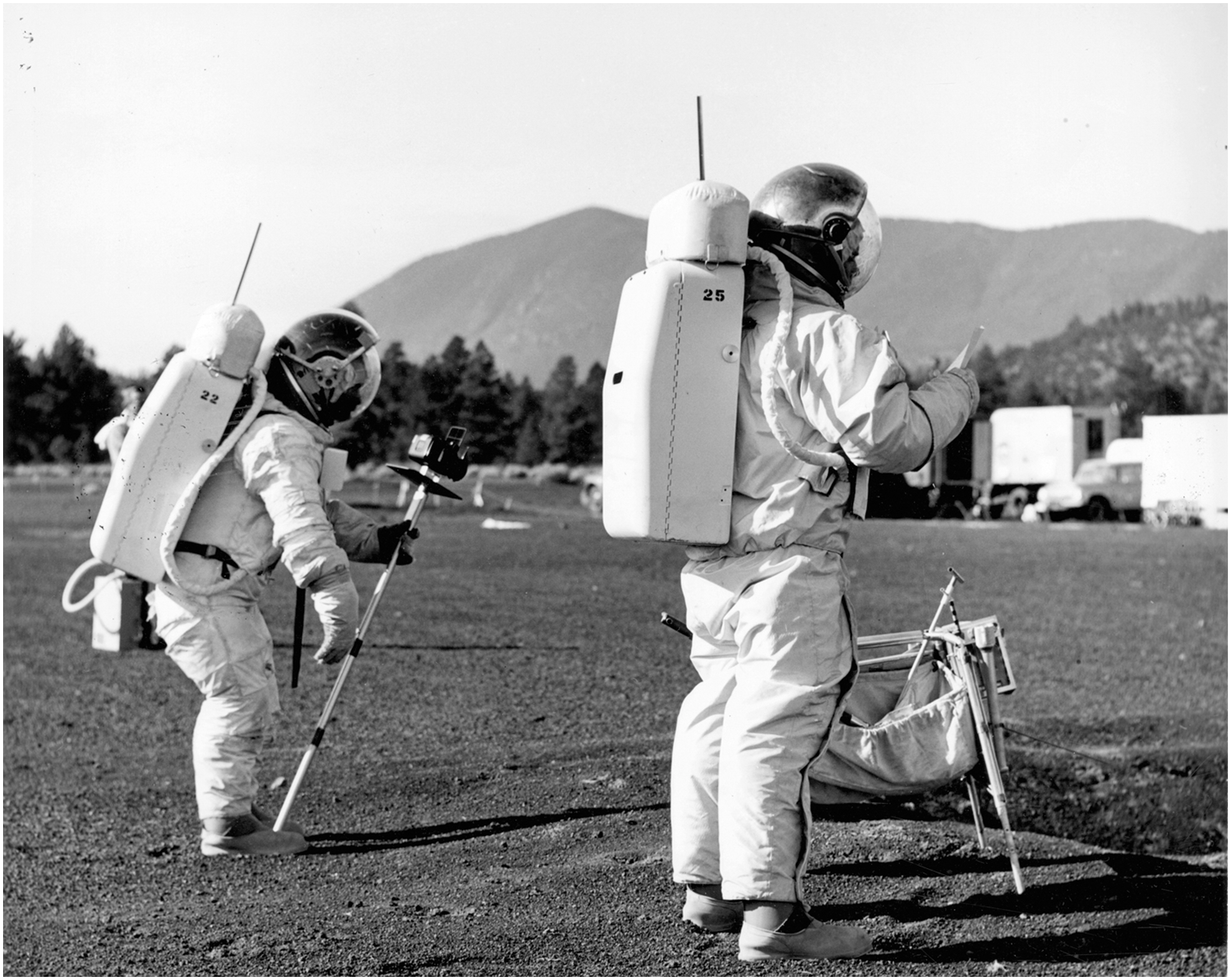
Two USGS geologists in space suits conduct a simulated lunar surface mission at the Cinder Lake crater field east of Flagstaff. Paul Switzer Collection, NAU.PH.426.467, Center of Astrogeology, USGS, Photo No. 116478, Cline Library Special Collections and Archives, Northern Arizona University, Flagstaff, Arizona.
In addition to these previous analog efforts, NASA's Science Mission Directorate has supported analog field testing for a variety of scientific, operational, and technical space exploration applications. One such example is the Pavilion Lake Research Project (PLRP; Lim et al., 2011), which conducted science-driven field activities under various (lunar, asteroid, Mars) simulated human exploration mission scenarios. Rather than focus on the engineering systems, tools, and timelines as the DRATS and other analog teams did, the project focused on developing the scientific methods that could be implemented during human exploration and the resultant systems, tools, and timelines that evolved from this design, build, and test campaign. The team's high-fidelity telecommunications infrastructure was first implemented during the 2009 PLRP analog campaigns and supported remote telecommunications under zero second, 50 seconds, 5 minutes, and 10 minutes one-way-light-time latencies. The methods used to enable the integration of these latencies within the PLRP deployments established an implementation baseline for future analogs, such as BASALT, with a variety of the tested architectures and successful technical elements being carried forward into other test environments for further maturation (Lim et al., 2011).
Given that many of these analog deployments deal with scientific and exploration scenarios that have no true historical equivalent, the inevitable hurdles, inefficiencies, and failures experienced throughout this design-build-test approach are in many ways the prized elements of these types of simulations for the operational and technical communities. The BASALT telecommunications team members have designed telecommunications infrastructures for all DRATS, (NASA Extreme Environment Mission Operations) (NEEMO), and PLRP analog field deployments, leveraging these prior analog experiences to design and implement the architecture described in the subsequent sections.
2. Methods and In-Field Infrastructure
2.1. Designing a Mars-relevant field telecommunication infrastructure for human exploration
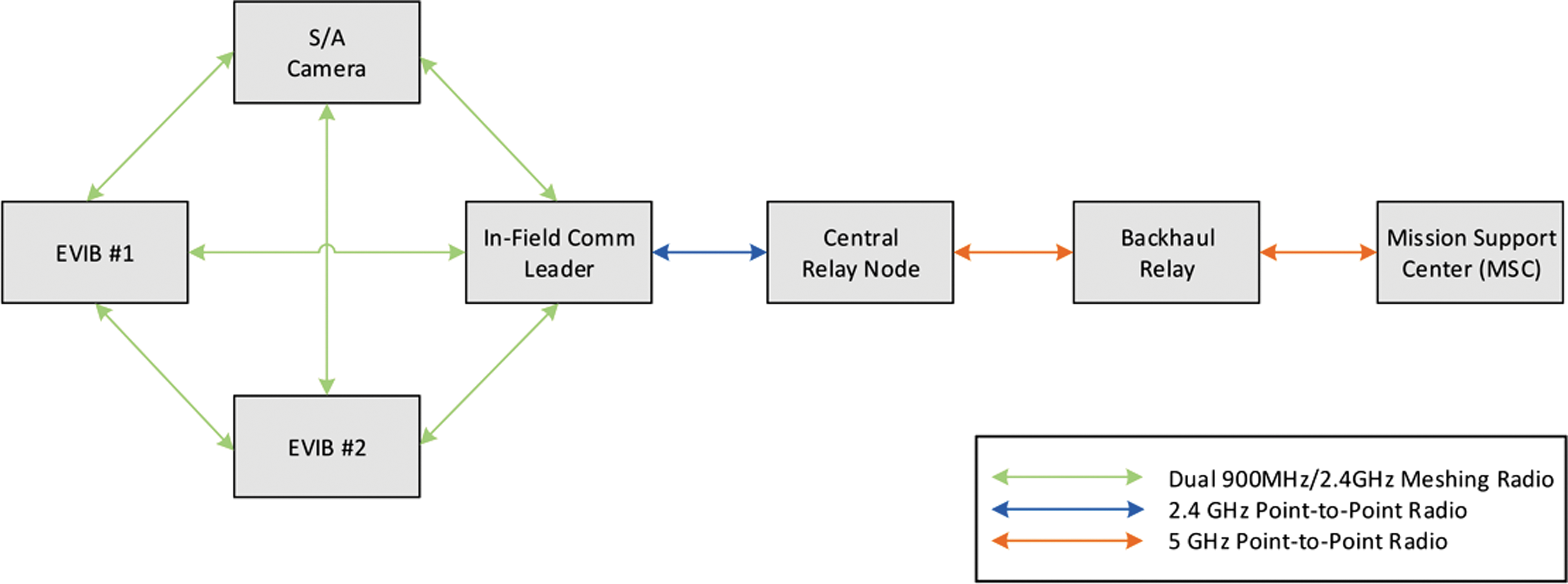
The team responsible for the design and implementation of the BASALT telecommunications architecture gained expertise through several prior NASA analog projects (PLRP, DRATS, NEEMO, and Regolith and Environment Science and Oxygen and Lunar Volatile Extraction [RESOLVE] projects) over the last 10 years. With this history, the team was able to design and build mid (Level 5–6) Technology Readiness Level (TRL) 1 systems that carried a pedigree from testing in previous missions. Operating with a mix of new and field-proven equipment reduces risk with enough margin to experiment with state-of-the-art technologies. The resulting architecture is shown in Fig. 3, which was adapted from the work of Lim et al. (2019) to illustrate each architectural component and support subsequent discussion.
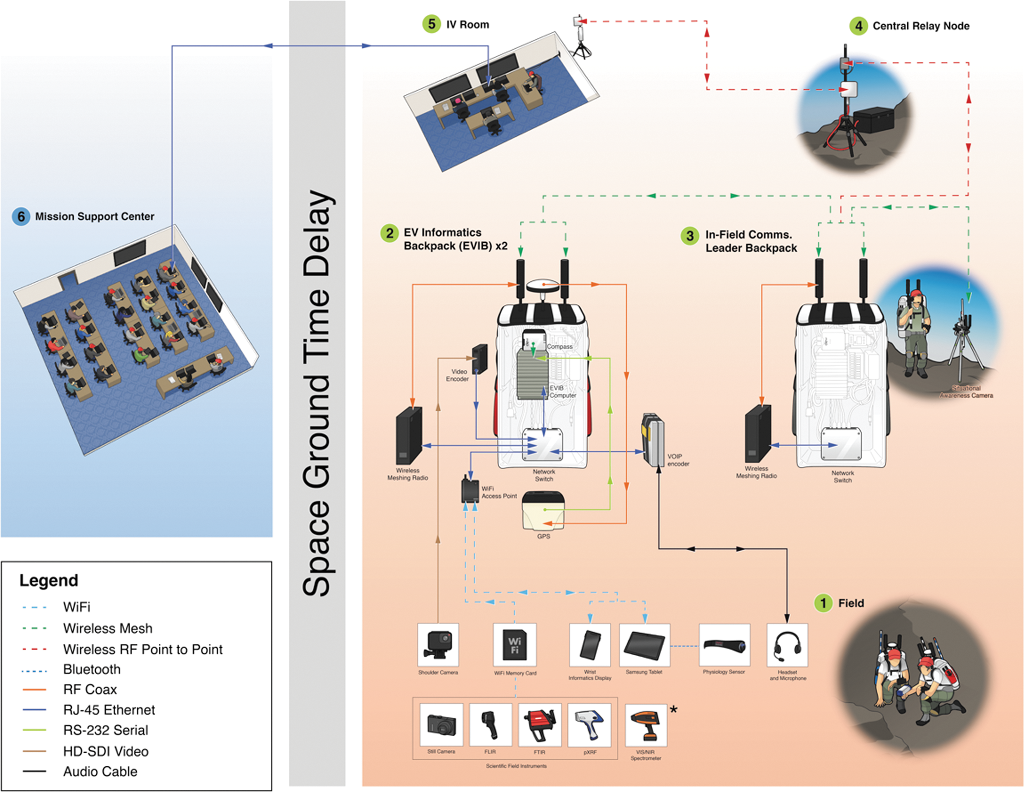
BASALT In-Field communications architecture. Solid lines show wired connections, and dashed lines illustrate wireless connections. Arrows indicate data flowing unidirectional or bidirectional. Elements 1–4 were physically located in the field, and elements 5 and 6 were physically located at base camp. For a more complete discussion of the BASALT concept of operations, Fig. 2 of Lim et al. (2019) provides an overview diagram illustrating how the time delay is carried through the major elements of the BASALT mission architecture.
In the planning phase of the BASALT program, the hardware and software teams considered how simulation conditions, such as time delay, would be implemented (see Lim et al., 2019, for more detail). The Earth-side element on the network was the control room, or MSC, for the mission, where science and operations support staff were located. The MSC was located approximately 30 km and between 5 and 15 km from the BASALT-1 (Idaho) and BASALT-2 (Hawai‘i) field sites, respectively. Users and hardware resided on a wired ethernet that operated on “Earth time.” The IV crew members were located in a room adjacent to the MSC and operated on a separate wired network on “Mars time.” In-Field elements and IV crew members were connected through wireless transmitters on “Mars time” as detailed by Lim et al. (2019). As a general design principle, wired networks were used wherever possible because of the increased performance and reliability over wireless networks.
Section 2.2 details the specific implementation strategies involved in setting up and utilizing this architecture. All elements of the telecommunications architecture are broken into segments and discussed at length in the subsequent section. For capability assessments on the utility and acceptability of the hardware, please refer to the work of Beaton et al. (2019a).
2.2. The constituent elements of the BASALT telecommunication architecture
The telecommunications infrastructure was divided into three segments (see Fig. 4). The first segment consisted of a node with point-of-presence (POP) connection with a local Internet Service Provider (ISP). This node was required to connect to servers and team members at other NASA Centers and Universities, for outreach events and general administrative Internet usage. Typically, this connection is purchased as a service from a local ISP, or terms are negotiated with a local government facility.
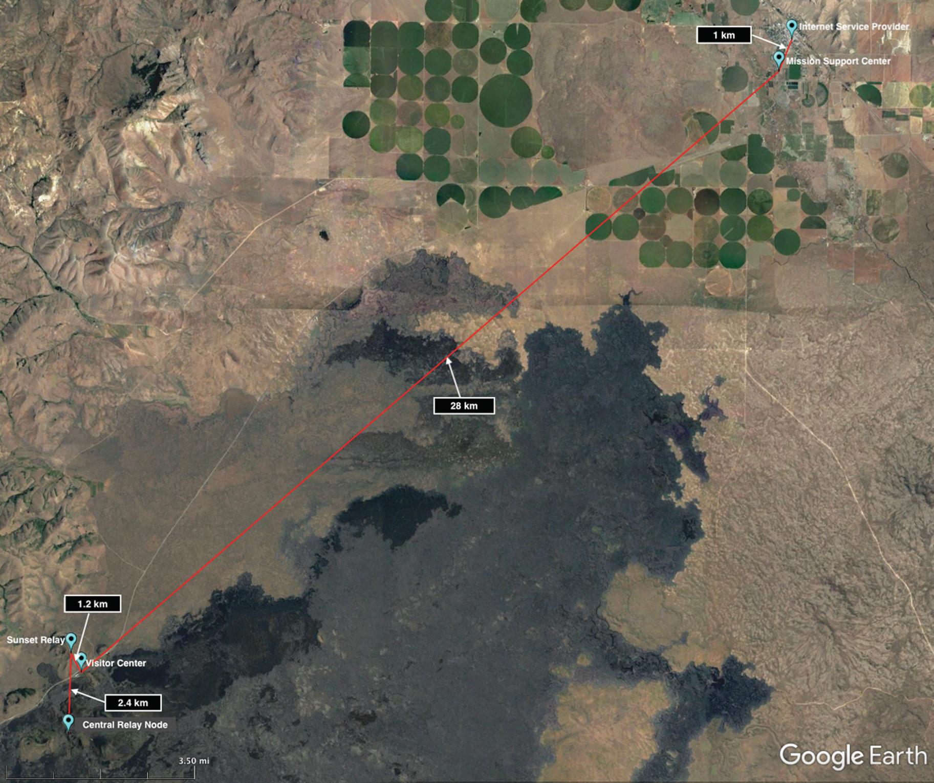
BASALT-1 (Idaho) point-to-point backhaul communications links with distances in kilometers.
Segment two consisted of the network connection that bridged the ISP node to the MSC. Depending on the distance, the connection can either be made with an Ethernet cable (as was the case in Hawai‘i) or point-to-point microwave radio frequency (RF) transmitters (required in Idaho). The telecommunication team located all of its enterprise-level (i.e., more robust and higher reliability than standard consumer-grade) equipment in the MSC, which included network servers along with networking and telecommunication equipment (e.g., routers, network switches, Wi-Fi Access Points).
The third wireless segment was the high-bandwidth point-to-point microwave RF telecommunication links that connected the MSC to the Central Relay Node. This segment was comprised of three wireless links for Idaho (as shown in Fig. 4) and two wireless links for the Hawai‘i deployment. Each telecommunication link was comprised of two transceiver nodes (one at opposing ends of the link), and these nodes were powered by a combination of batteries and solar panels, depending on accessibility. If the node could be easily accessed in the field, smaller batteries were used, recovered, and recharged each day. In less accessible areas, larger batteries with solar panels were temporarily set up with Internet Protocol (IP) network-connected voltage monitors and staged for the duration of the mission. This segment terminated with the Central Relay Node, which connected via Ethernet cable to the final segment, the wireless meshing field infrastructure.
All the field elements connect to the Central Relay Node through the wireless meshing network. These elements included the EVIB, Mobile Instrument Platform (MIP), In-Field Comms Leader, and the Situational Awareness (S/A) camera. The agile nature of meshing networks enabled flexibility in the traverse planning and mobility for the crew member (Fig. 3).
2.2.1. Wireless telecommunications infrastructure
Wireless telecommunication capabilities will be central to the design of a human planetary mission (Seibert et al., 2019). For the BASALT program, the telecommunications team investigated a variety of methods and protocols to deploy a high-TRL system comprised largely of commercial off-the-shelf (COTS) products that aligned with NASA's current architecture roadmap (NASA, 2014). To realize this architecture, a variety of radio configurations were implemented in commercially available frequency bands, specifically:
In general, the available bandwidth increases as frequency increases, but the ability to diffract around or reflect/scatter off of objects decreases (Seybold, 2005). With that basic constraint in mind, there were a few optimal frequency bands for our surface wireless network for our given In-Field work environments; the telecommunications team selected 2.4 GHz for the higher bandwidth and 900 MHz for its favorable propagation characteristics relative to 2.4 GHz. The 2.4 GHz frequency band is generally preferred in line-of-sight applications, while the 900 MHz spectrum band will diffract around some obstructions. These frequency ranges also have a large number of COTS antennas, cables, and connectors that reduced overall cost and procurement time. Despite the high commercial usage of these frequency bands, spectrum allocation was manageable since our field tests were located in remote areas.
One unique technology implemented for the BASALT program was a wireless mobile meshing telecommunication system that provided dual-band redundant radios for every node on the network, operating in the 2.4 GHz and 900 MHz frequency bands, to optimize data throughput and minimize loss of signal. The internal firmware on each node controlled which of the two radios sent the data based on a packet delay calculation running between all radios on each node of the meshing network.
From prior experience designing telecommunications systems for other NASA analog missions, the telecommunications team determined that a meshing radio system was the optimal telecommunication method for the elements within the exploration zone of a planetary surface. Figure 5 provides an overview of the wireless architecture implemented for BASALT.
Simplified drawing of the RF communication nodes for the BASALT-2 (Hawai‘i 2016) field deployment.
2.2.2. Wired telecommunications infrastructure
The reliability advantages of wired local equipment are critical to overcoming fieldwork data network challenges. Early in the planning process of BASALT, all servers for the deployments reside locally in the MSC. The Quality of Service from local ISPs can be unreliable, and bandwidth is limited. The reduced bandwidth from the ISP can translate to lost data and reduced mission success when the servers are remote and distributed through a secure virtual private network (VPN) tunnel that connects to the field infrastructure. By providing servers that physically resided in the MSC, network connection speeds and reliability were improved while minimizing the frequency of signal outages. Additionally, local wired server access provided the telecommunications team with the ability to troubleshoot and monitor using network visualization tools, allowing for rapid discovery and resolution of anomalies. Another benefit to this configuration was that most of the telecommunication team supported each EVA from the MSC, so troubleshooting was more easily performed with equipment also located locally in the MSC.
During the BASALT-1 Idaho 2016 deployment, a 53' Mobile Mission Control Center (MMCC) was used from Kennedy Space Center as the MSC (Fig. 6). This mobile asset was specifically designed and configured to support remote analog missions. The MMCC was divided into three rooms: the front equipment room, the main MSC, and a smaller back room which was used by the IV team. A total of 16 console positions were provided, and each was comprised of a computer and three monitors. A separate front room was equipped with a hardware rack which housed servers, a network-attached storage device, router/firewall, network switches, and patch panel. This provided a flexible network configuration for the MSC requiring minimal additional wiring.
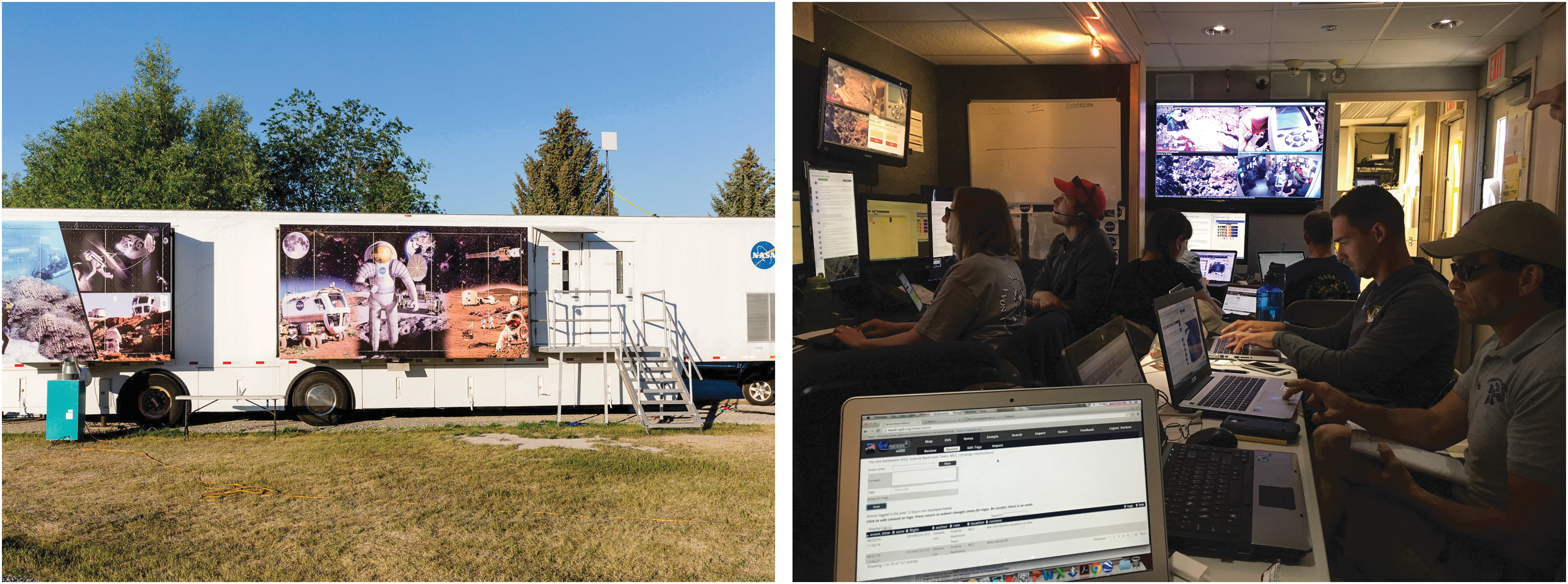
The MMCC shown configured as the MSC for the BASALT-1 (Idaho 2016) field deployment. (
During the BASALT-2 (Hawai‘i 2016) deployment, a temporary setup was required, so the telecommunications team retrofitted a large conference room as the MSC (Payler et al., 2019). A design was conceived which consisted of wired Ethernet connections for each console position and a separate, isolated network for the IV workstations since those personnel accessed data real-time from the field, as opposed to the delayed feed in the MSC. The servers, router/firewall, and network-attached storage device were all colocated together in the same physical location and connected through a network switch which was configured for two separate networks, thus separating the MSC and field network.
2.2.3. Voice telecommunications
The BASALT voice system consisted of several different system components tailored to the needs of the EV crew members, MSC, and Field Support Team (FST). During the Intra-EVA portion of the mission, there was near-constant, no-delay, bi-directional communication between EV and IV crew members, delayed communication between IV crew members and MSC, and the MSC was able to listen to EV crew member communication over the Mars delay. The BASALT analog voice infrastructure resembled the architecture currently planned for a human exploration mission in a simplified, less redundant configuration (Drake and Watts, 2014). It is anticipated that in future human exploration missions there will be redundant telecommunications links of varying bandwidth to assure that, at a minimum, there is voice communication with the EV crew. For BASALT, the architecture did not include a redundant low-bandwidth backup voice telecommunication link. Figure 7 shows the block diagram for the voice system.
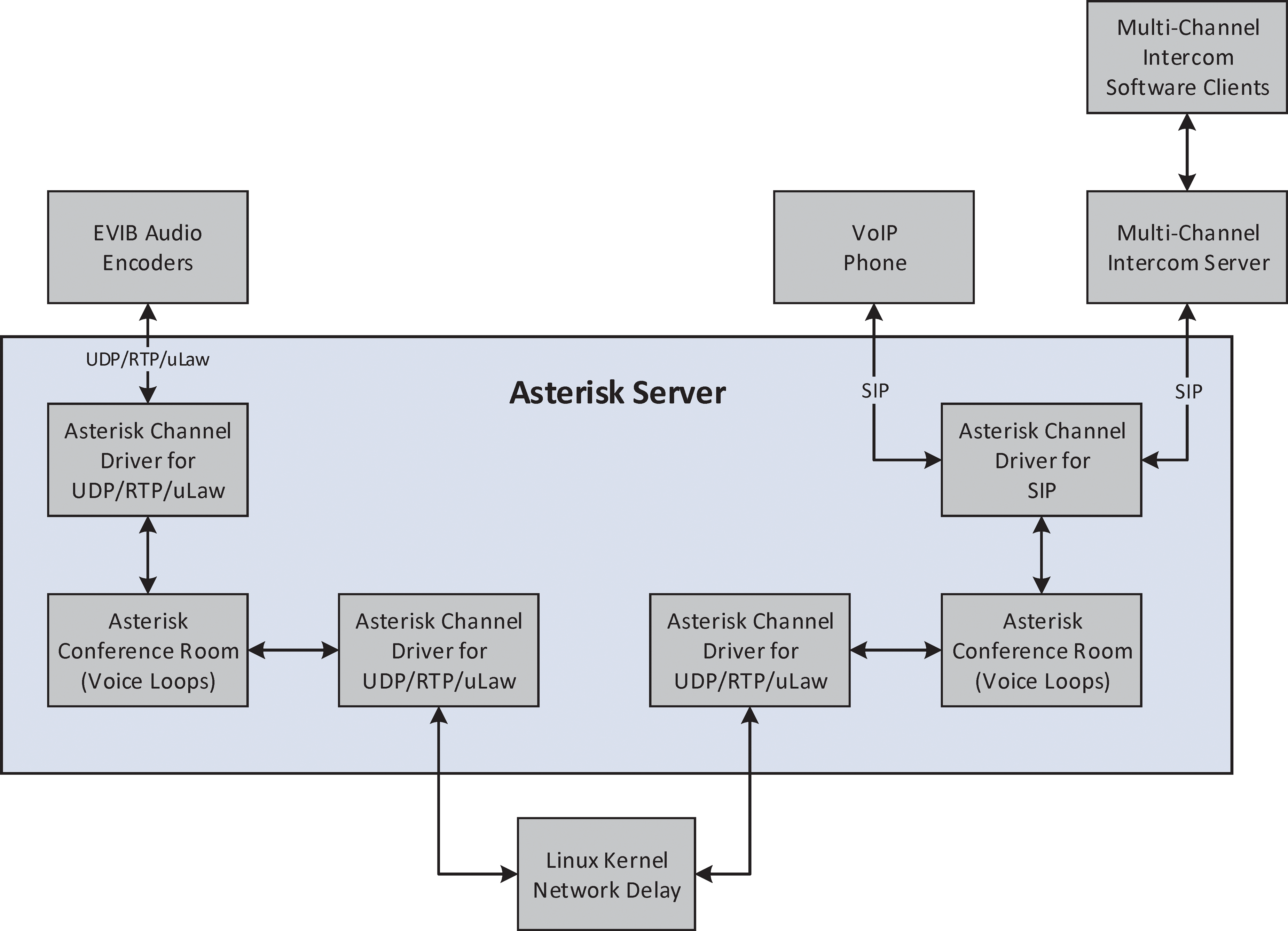
Block diagram showing all major hardware and software pieces of BASALT voice architecture. RTP, Real-Time Protocol.
The hub of the voice infrastructure is an Asterisk voice server. Asterisk is an open source framework for multiprotocol, real-time communications applications. The framework is comprised of several different modules that provide the flexibility necessary to scale and integrate a variety of different clients onto one platform. This voice server was physically located in the MSC during field tests and connected to other devices through a standard IEEE 802.3 ethernet interface.
The voice channels between the MSC and field, or “Earth” and “Mars,” were interconnected with a variable delay that could be manually set, depending on the test condition (5 or 15 min). Within the Asterisk server, two User Datagram Protocol (UDP) channel drivers were created and connected with a Linux kernel. The channel drivers were built into the Asterisk framework and instructed Asterisk how to send audio over the network. In BASALT, it was configured to send and receive raw Real-Time Protocol (RTP)/UDP packets. RTP operates over UDP and was designed for real-time transfer of streaming media (Lazzaro, 2006). When an Asterisk server sent a UDP packet in either direction, the Linux kernel delayed the data, and the Asterisk server received the delayed packet.
Team members working in console positions in the MSC used a software-based multichannel intercom system to provide multichannel, full-duplex voice in a similar fashion to the Mission Control Center in Houston, Texas. In this configuration, users can talk and listen at the same time, similar to a telephone. Additionally, users were able to talk and listen to multiple voice loops at the same time. These individual clients were all connected to a client server located in the MSC that connected to the Asterisk server. The two servers were physically connected with an ethernet cable on the same network, and the data were sent over Session Initiated Protocol (SIP) as defined by Rosenberg et al. (2002). This signaling protocol enabled configuring, modifying, and terminating real-time sessions between participants on an IP data network. SIP was primarily used to enable voice telephone, or Voice over IP (VoIP). In addition, the voice network supported communication between the FST, the telecommunications team, and MSC support staff. To minimize additional hardware and provide the greatest flexibility, the iOS or Android version of the software client used in the MSC was provided to these key field positions, and users connected to a Wi-Fi Access Point (AP) located on the S/A camera to access the voice network. EV crew members used dedicated VoIP hardware as discussed in Section 2.3.3.
2.3. EVA informatics backpacks
For the BASALT project, the EV crew members were required to traverse across variable, uneven terrain and be physically mobile (i.e., able to crouch on hands and knees, swing a hammer, etc.). There were several design challenges to overcome with the stringent terrain requirements, such as obtaining a balance of increased hardware durability and mobility without adding significant weight. The new BASALT EVIB were lighter, more compact, and provided a center of gravity conducive to traversing over rough terrain as compared to prior EVIB configurations utilized during DRATS (Abercromby et al., 2013). The internal organization of the primary hardware components are shown in Fig. 8. The following sections discuss the constituent subsystem elements of the EVIB.
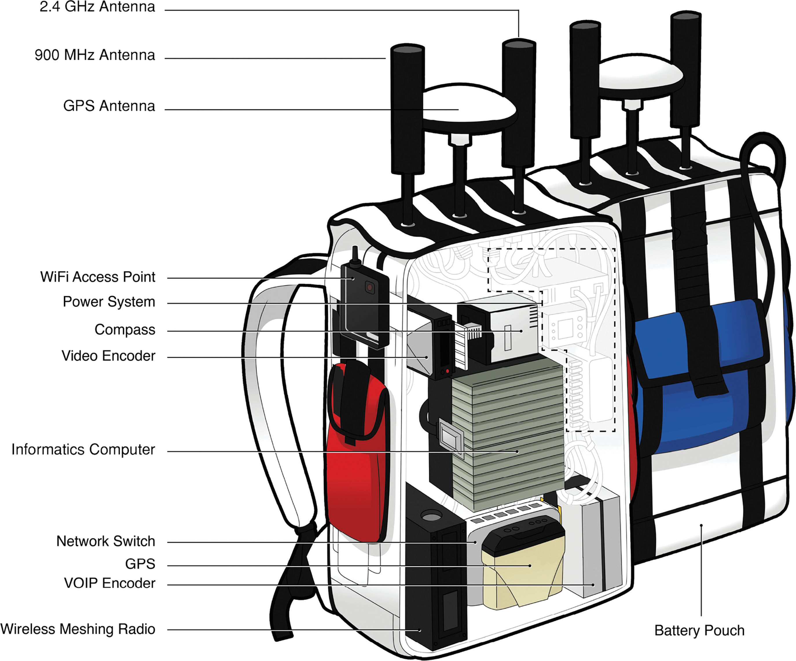
Cutaway view of the EVIB showing all major hardware components. Modified from Lim et al. (2019).
2.3.1. Outer textile shell and modular storage compartments
The softshell backpacks of the EVIB, designed and built in collaboration with Mission Workshop 2 , fit the rigid electronics enclosure and supported the load by reinforcing the backpack with extra straps, clips, stitching, and alpine-style load lifters (see Fig. 9). Solutions were crafted for mounting the shoulder camera, antennas, cable routing, and maintaining easy access to the batteries. There was a “one size fits all” requirement for these backpacks, in order to minimize the daily changes between crews and to keep within the project budget. The backpack designers accomplished this by fabricating interchangeable waist belts and vertically adjustable shoulder straps. To comfortably carry the load, thicker padding on the shoulder straps was added.
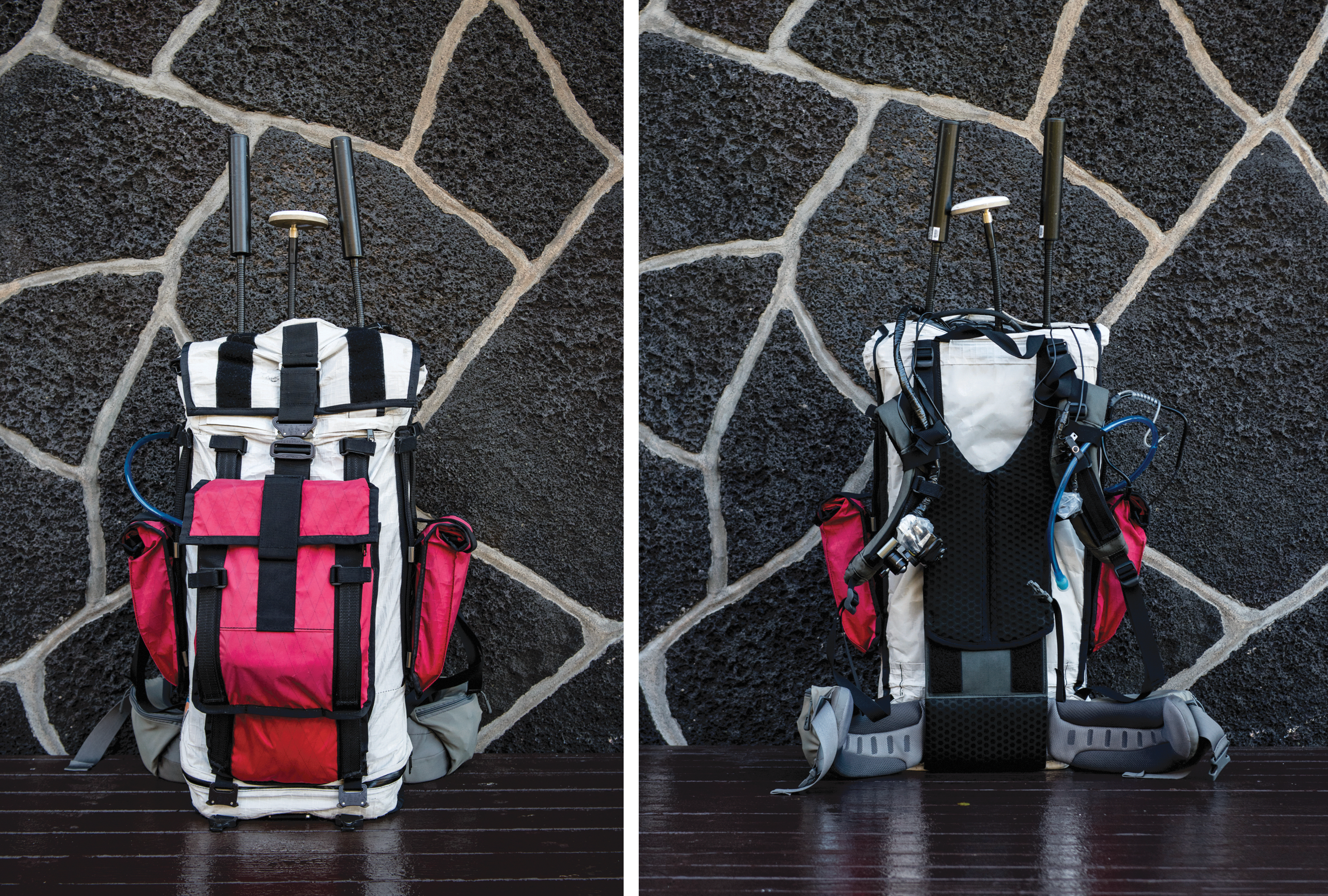
EVIB shown fully packed after pre-EVA preparations. Credit: J. Sathngam.
Due to the modular nature of the backpack design, there were also modular storage compartments for spare batteries, tablets, and ice packs (for hot days). The backpacks were constructed from a variety of high-tech Dyneema fabrics that provided water and abrasion resistance. The white color also helped reduce heating effects from the Sun. The external storage compartments were color coded to represent the EV1 Operations lead (Blue), EV2 Science lead (Red), and Telecommunications relay node (Gray), so that the operators could be distinguished in images and video.
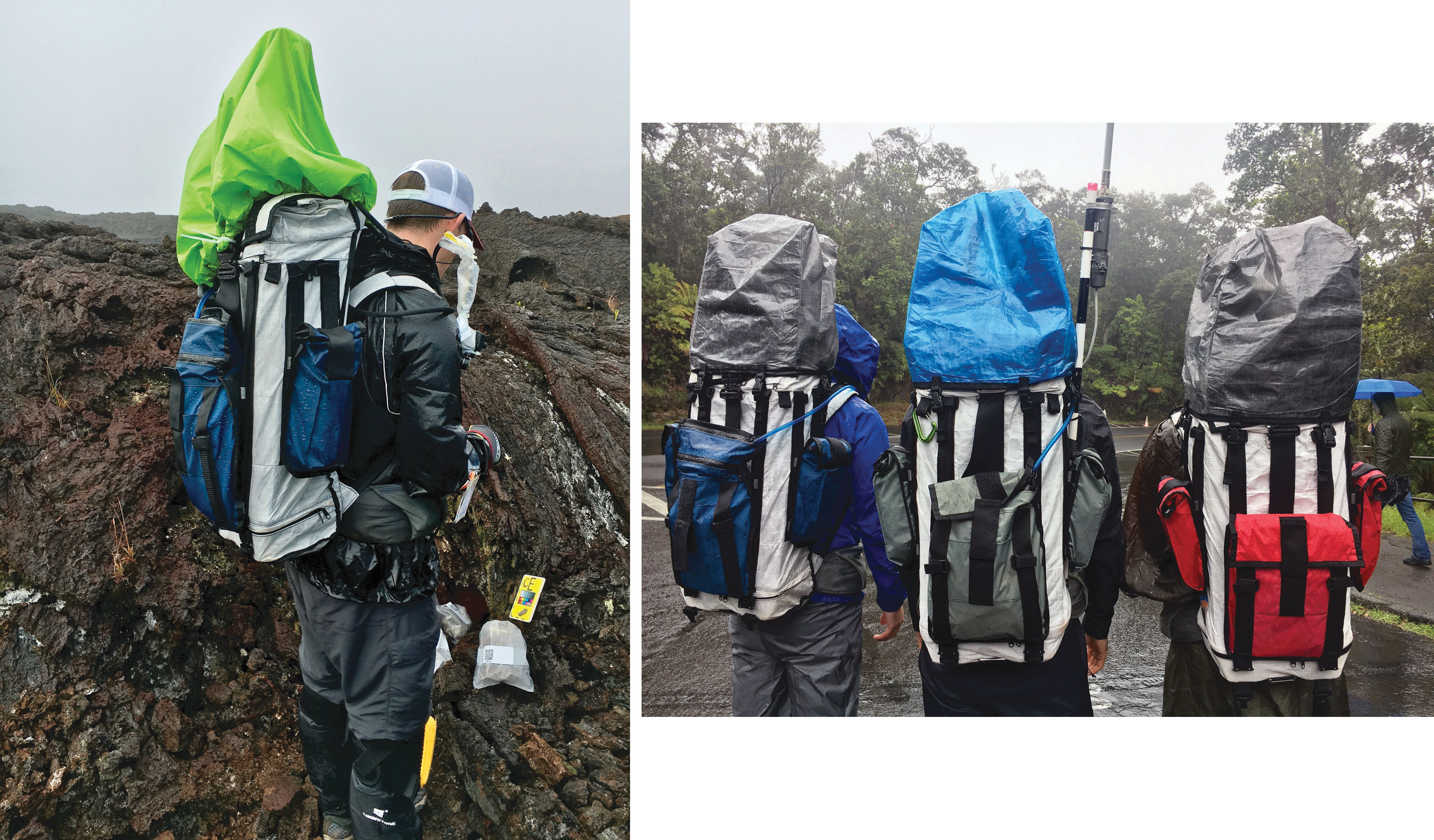
A key issue of field analog work is contending with the weather elements such as extreme heat or rain. When the design for the backpacks was first conceived, it was agreed that the EVA would terminate if there was more than a light rain at the field site. On one of the BASALT-2 (Hawai‘i 2016) mission days, significant rain and wind threatened termination of the EVA, but the collective team agreed to continue with the EVA if the equipment would not be damaged and the field team was not at risk (e.g., no lightning). Rain flies from the spare FST's backpacks, along with zip ties, duct tape, and black plastic trash bags provided a temporary In-Field waterproofing solution to get through the EVA (Fig. 10, Left).
(
Following the BASALT-1 deployment to Idaho, a lightweight, waterproof, packable cover that could be quickly installed by the FST was fabricated to protect the antennas and open cable ports on the top of the backpacks (Fig. 10, Right). The EVA shoulder cameras were permanently covered with heavy-duty plastic and electrical tape, and the wrist display was stored in a waterproof accessory pouch on the EVIB.
2.3.2. Position and navigation system
Since one goal of analog field work is to evaluate the application of technologies for use in future spaceflight missions, BASALT implemented GPS in the EVIB as a COTS product that provided the required capabilities of position and navigation. While there is disagreement about the exact position and navigation requirements planned for future missions, there is agreement that a method that resembles GPS will be implemented to locate and monitor surface assets.
The GPS units provided 1.5 m resolution in the L1 band. A digital compass was included in the backpack navigation suite to provide heading and dual axis tilt information. While a relative heading could be obtained with GPS, the compass provided absolute heading without movement. Both devices sent data through an RS-232 serial connection directly into the backpack computer.
The GPS data were then incorporated into the Exploration Ground Data System (xGDS) software suite which provided route planning and real-time annotation tools to the mission support team (Marquez et al., 2019). Before each mission day, the team would plan a traverse path for the following day with candidate sample locations. All of this information was entered onto the xGDS server, and that plan was subsequently sent to the wrist displays used by crew members. By having a planned position and heading, crew members could see their own positions relative to the traverse path and candidate sample locations. Their position and heading from the backpacks were also sent over the wireless network to a server and subsequently integrated into the Minerva mission tool suite and used by the mission support and IV teams to guide the crew members and make annotations during an EVA. The Minerva suite consisted of these software tools: xGDS, Playbook, and Surface Exploration Traverse Analysis and Navigation Tool (SEXTANT) (Marquez et al., 2019).
2.3.3. Voice system
Each backpack contained an audio encoder that served as a gateway between the analog audio headset worn by the EV crew member and the Asterisk server located in the MSC. A specific channel driver was configured for these encoders and provided full-duplex communication with the BASALT voice system. The encoders operated on a single channel that was configured to be the primary voice loop for the analog mission. There was direct, two-way communication between EV and IV, but only one-way from EV to the MSC (see Marquez et al., 2019, for details).
The EV crew members wore monaural headsets with a single boom-arm microphone. Safety, clarity, comfort, and wind noise mitigation were the primary design considerations. With a monaural earbud, one ear was left open to maintain situational awareness of the surroundings while a noise-blocking ear bud in the other ear enabled crew members to clearly hear audio from voice loops, even in high wind conditions. The microphone was a typical boom arm–style microphone with a digital signal processor for noise cancelling and an aggressive windscreen made of faux fur. While these accommodations suppressed wind noise, wind distortion still persisted to some extent.
2.3.4. Imagery system
The EVIB supported streaming video and still images during the BASALT project. To determine the optimal streaming video camera placement, cameras were attached to the head and chest of two test subjects during a precursor reconnaissance trip to an area with similar topography to what would be seen in the BASALT project. Afterward, the video was analyzed by team members who determined that the chest would be a more appropriate mounting location, primarily because the head-mounted perspective produced too much erratic motion. Additionally, head-mounted video cameras were cumbersome and conflicted with other headsets, safety glasses, and the associated cabling. As the design of the backpacks matured, the video cameras were moved from the chest to the shoulder strap of the backpack on a custom webbing rail. This design change eliminated a camera harness from the already encumbered crew members.
The video camera provided an output resolution of 1920 × 1080 pixels at 30 frames per second (FPS) and had a High Definition Serial Digital Interface (HD-SDI) Bayonet Neill-Concelman (BNC) video interface to ensure a robust physical connection between the camera and the EVIB video encoder. The camera was also powered by the 12V direct current (DC) bus voltage on the backpacks, which added stability to the configuration over a micro-USB connector.
Before the video signal could be broadcast over the network or ingested by the informatics computer, the HD-SDI video signal was converted to an IP-encoded H.264 digital stream. This encoding format has become the industry standard as it allows for lower latency and better image quality at lower data rates versus other encoding schemes. The video encoder sent two video streams over IP: one to the informatics computer at full resolution for local recording and a second stream with a resolution of 1280 × 720 pixels at 30 FPS over the wireless network to IV and the MSC. The 1280 × 720 pixel stream was sent over the network to limit the amount of bandwidth used for video.
Still imagery was provided by a rugged point and shoot 16-megapixel camera that the EV crew members stored in their hip belt pocket. The still camera used a Wi-Fi SD card to communicate with an AP located on the EVIB. Once an image was taken with the camera, the file was transmitted over the telecommunications network into the xGDS server for IV crew members and (after time delay) the MSC personnel.
2.3.5. Power system
The power system was anchored by dual 12V DC lithium-ion batteries that could be exchanged during a mission without losing power to the electronics. They provided enough power to run the EVIB system for a standard 4-hour EVA. All hardware was either directly powered by the 12V DC bus voltage or by Power Over Ethernet (POE) where a DC voltage is applied to unused conductors on an Ethernet cable and eliminates the need for a separate power cable. In the cases where POE was used, the injectors were powered by the 12V DC bus voltage. To protect the equipment, the batteries were connected to a device that monitors and protects equipment from overvoltage and undervoltage. Each piece of hardware was connected to a Deutsches Institut für Normung (DIN) rail-mounted circuit breaker that minimized the risk of an overcurrent event.
2.3.6. Communication system
The primary protocol used to interconnect wired devices inside the EVIB was IEEE 802.3 Ethernet. These devices connected through an industrial POE network switch. By using POE, power and weight were conserved, and the overall electrical design was simplified. With IEEE 802.3 being such a prolific standard, there were many IP-ready COTS hardware solutions that met the requirements for the EVIB subsystems.
During development, the wireless meshing radio could not reliably act as a 2.4 GHz Wi-Fi AP for connecting wireless components on the backpack due to internal limitations of the meshing radios. An intermediate solution of using a small Wi-Fi AP inside the backpacks proved to be unsuccessful because the aluminum base plate of the backpacks blocked too much of the RF energy. Therefore, an AP that was external to the electronics enclosure, but still inside the backpack, was implemented. This solution provided the reliable connection that was needed to support the informatics wrist display, still camera, scientific field instruments, and physiology tablet.
Finally, EV crew member safety was a priority in the design of the EVIB, especially for the telecommunication systems. For the RF devices, maximum permissible exposure limits were calculated for humans in an uncontrolled environment. Antenna placement and power levels of the equipment were designed accordingly. For the power system, the batteries had a proven safety and reliability track record.
2.3.7. Informatics wrist display system
In addition to managing information to be sent to the IV and MSC operators, an informatics wrist display was also implemented to provide the EV crew members with various sources of information. The display consisted of an iPhone 6 Plus mounted on the EV crew member using an armband case (Fig. 11). An external battery was stored in a side pocket of the EVIB and connected to the iPhone for the duration of the EVA to allow for continuous runtime. The wrist display connected via Wi-Fi to the backpack AP for its data connection. Pre-mission checkouts of the wrist display could be time consuming (up to 45 min) when there were issues connecting to the servers in the MSC. Once the connection was established, it was stable for the duration of the mission day. The software running on the wrist display included xGDS traverse planning software to show daily traverse, way points, and current location of crew member; Playbook timeline and mission log; hardware status of the EVIB; and a live view of the shoulder camera (to aid in pointing) (see Marquez et al., 2019, for details).
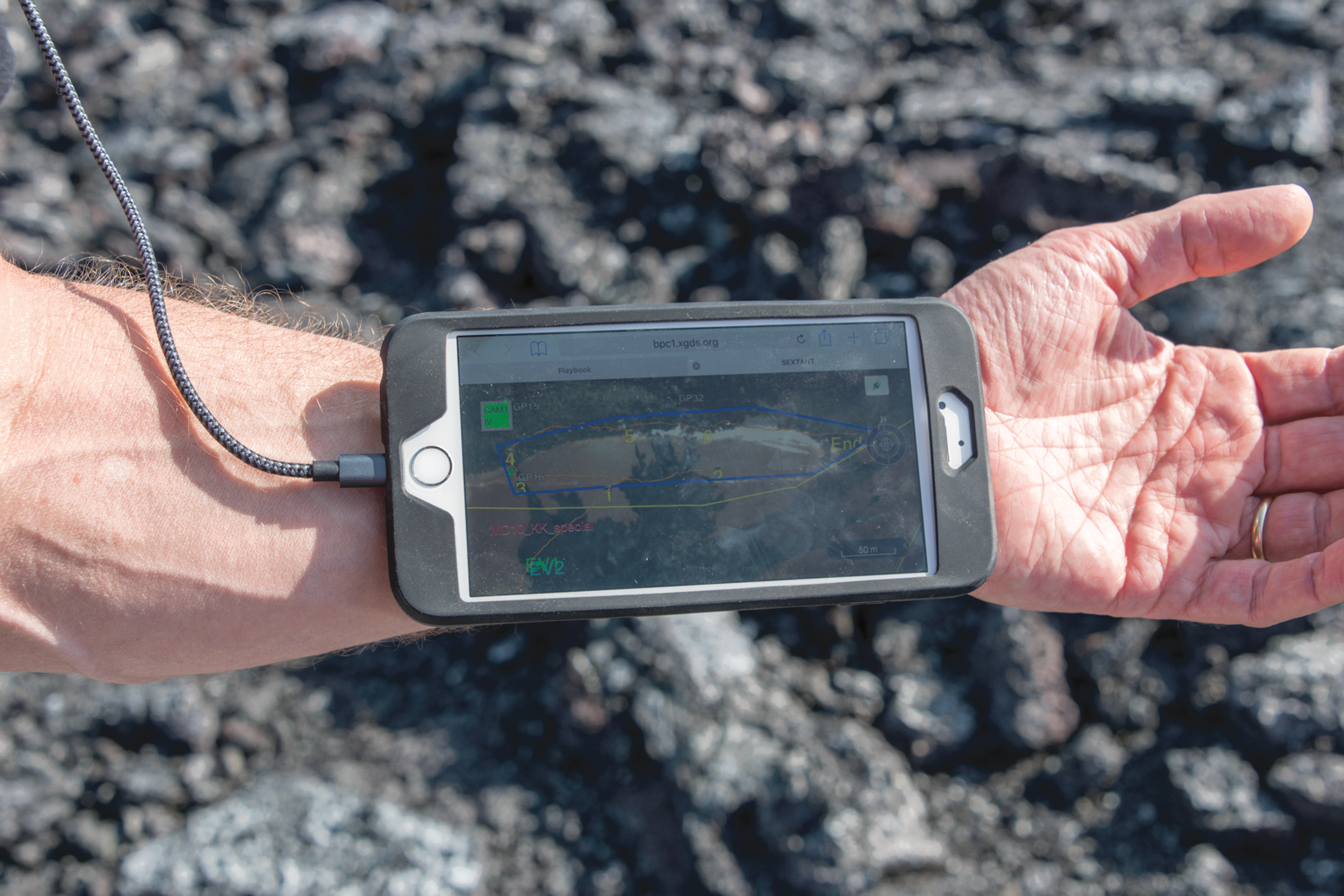
Informatics Wrist Display shown during EVA with xGDS mission planning tool running. Credit: K. Beaton.
2.3.8. Physiological monitoring system
The BASALT EVIB also included a COTS physiological monitoring capability with data storage. Crew members wore the physiology monitor around their chest, and it provided heart rate, respiration rate, heart rate variability, along with posture, activity levels, and estimated core body temperatures. The telecommunications team devised a method to transmit the live data from the sensor through the telecommunications infrastructure back to IV since the sensor had the capability to transmit over only short distances (see Hill et al., 2018, for more details about this system).
2.3.9. Instrument systems
Two scientific instruments were used during simulated EVAs: a Bruker Tracer IV-SD X-ray fluorescence spectrometer and an ASD TerraSpec Halo portable visible-near infrared (VNIR) spectrometer. The X-ray fluorescence unit provided an elemental analysis on contact, while the VNIR spectrometer provided mineralogical information. For further details on instrument specifications, see Sehlke et al. (2019). All data was transmitted over the network to the MSC.
2.4. Mobile Instrument Platform (MIP)
The MIP was initially conceived as a payload on board a planetary vehicle ranging in size from a small rover to a large pressurized, manned rover (Lim et al., 2019 ). The core capabilities of the MIP included carrying science instruments, providing a telecommunication relay, transmitting science instrument data to IV, and providing an S/A camera for broad context video. For BASALT, the FST carried the science instruments throughout the mission and passed them to the EV crew members as needed. Data from the science instruments were wirelessly transmitted through the EVIB over the telecommunications relay provided by the In-Field Comms Leader EVIB. The S/A camera was a stand-alone unit managed by the communications field team. In this configuration, all capabilities were simulated by the various field team members working as one collective unit.
2.4.1. Situational Awareness camera implementation
In the human Mars exploration mission scenario envisioned by the BASALT program, an S/A camera (Fig. 12) was mast-mounted on the MIP (Beaton et al., 2019a). This camera provided both IV and mission support a broad contextual view of the EVA, to augment the cameras worn by the EVA crew members. To enable this capability, an action camera with a High-Definition Multimedia Interface (HDMI) output was connected to a video encoder that was connected to a wireless meshing node to stream the live video with a resolution of 1280 × 720 pixels at 30 FPS. A battery pack was sized to provide uninterrupted power for the duration of a mission day. All the hardware was secured to a portable lightweight tripod that the telecommunications team could safely carry across the BASALT field sites.
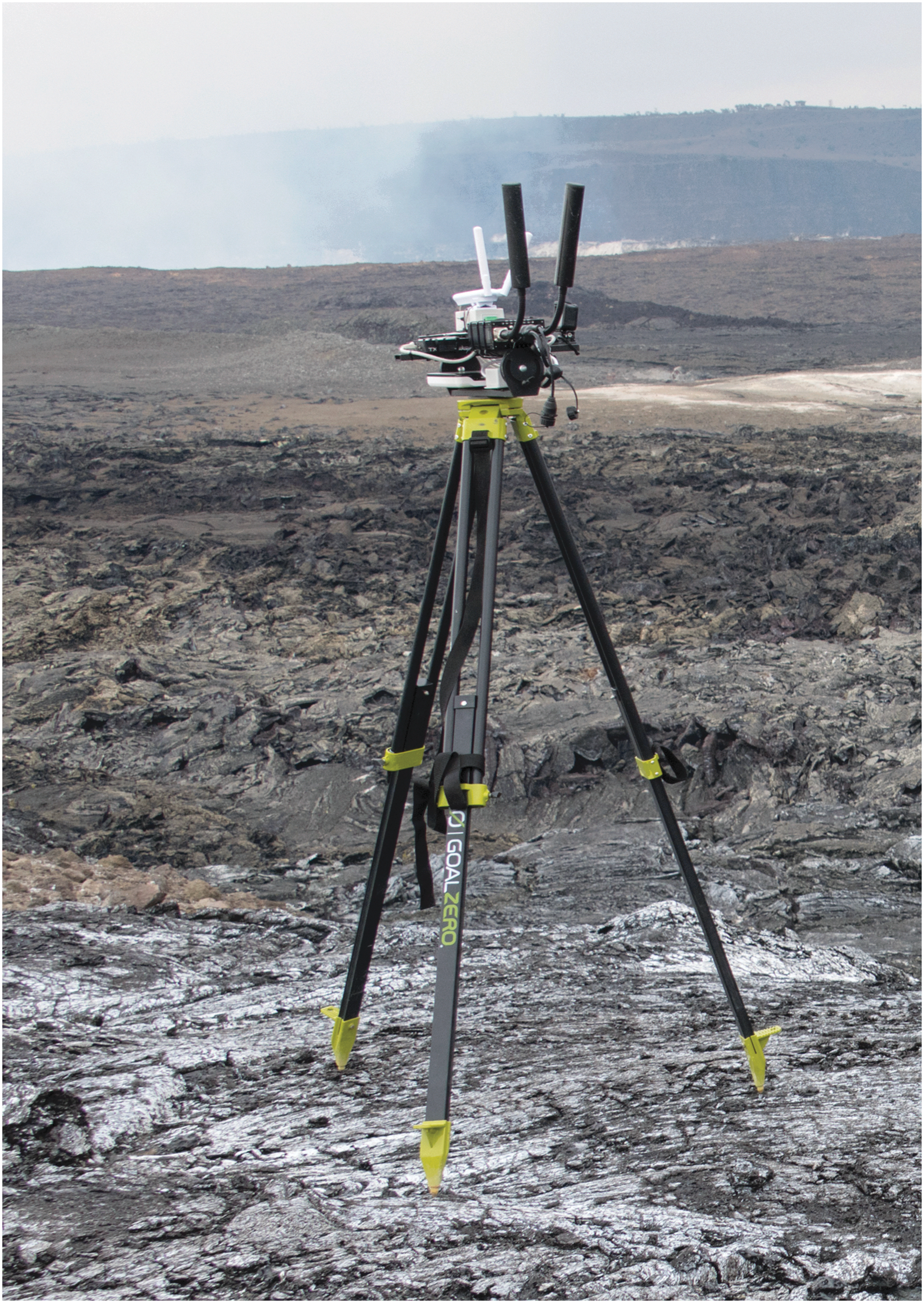
S/A camera with wireless meshing radio, camera, battery, and video encoder.
2.4.2. Mobile telecommunications relay
Also called the In-Field Comms Leader Backpack (Fig. 13), the mobile telecommunications relay consisted of the telecommunications system that was on the MIP in a real mission scenario. Having this hardware in a backpack configuration allowed for rapid, on-the-fly relocation as the EVA was underway since no vehicle could traverse the rugged terrain being explored. This backpack consisted of many of the same components as the EVIB, including the power system, batteries, along with the wired and wireless telecommunications systems. The wireless meshing radio in this backpack could connect with all the In-Field mission elements to provide connectivity back to the MSC through the Central Relay Node. The connection to the Central Relay Node was made through a secondary wireless radio on the backpack.

In-Field Comms Leader moving into position as a communications relay. Credit: J. Sathngam.
3. Communication Infrastructure Data Utilization
The primary test conditions which directly impacted the telecommunications infrastructure were the 5 and 15 min time delays and low/high bandwidth test conditions imposed between the field team and MSC. BASALT did not impose total budget limits on the test conditions but rather constrained the transmission rate of data. There was no delay between the local planetary surface elements such as EV, MIP, and IV workstation. Likewise, there was no delay within Mission Control elements. The 5 and 15 min time delays took place between these two functional analog locations of the deployment (“Earth” and “Mars”); see Lim et al. (2019) for more details. The low-bandwidth condition was defined as 0.512 Mb/s uplink and 1.54 Mb/s downlink, and the high-bandwidth condition was defined as 5.0 Mb/s uplink and 10.0 Mb/s downlink. Acceptability ratings of the various test conditions were studied and reported by Beaton et al. (2019b).
3.1. Bandwidth data collection methods
In order to determine the amount of data demand experienced during the BASALT EVA simulations, all network traffic was collected by a network data collection tool running on a server. The tool, called Netflow, provided the ability to gather and filter all network traffic as it entered or exited predetermined network interfaces. The entire network traffic was then filtered per element and sub-element (e.g., EV chest camera video, voice communications, physiological data). This provided the capability to calculate exactly how much data was transmitted/received between each component during each BASALT EVA.
For the BASALT deployments, the Netflow data collected during each EVA was decomposed into the following data elements: GPS and compass, voice communications, EV chest camera video, wrist display information, and physiological data. The following section provides a comprehensive description of the telecommunication network demand experienced for both the Idaho and Hawai‘i BASALT deployments.
3.2. Bandwidth data analysis
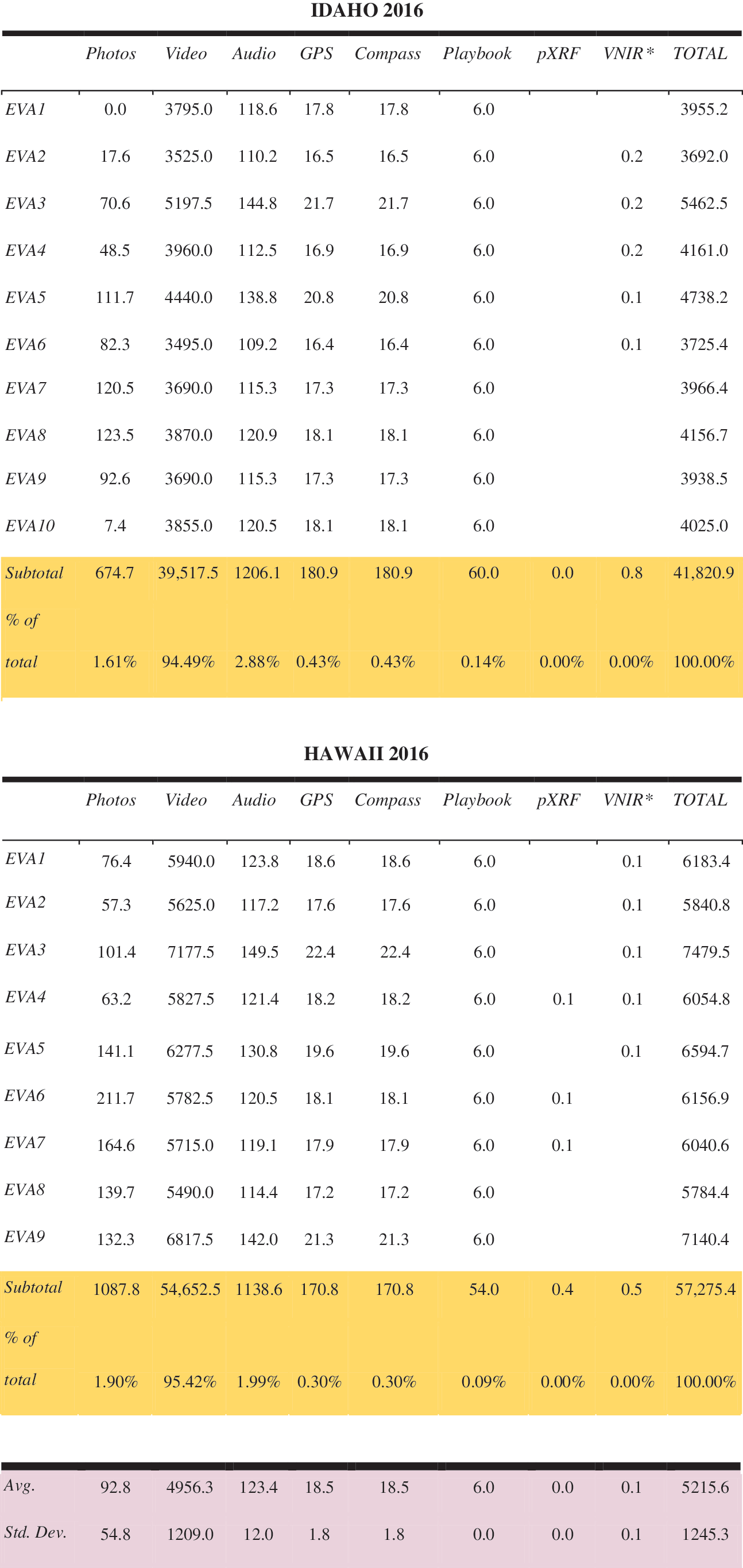
Data transmitted during the 2016 BASALT-1 (Idaho 2016) and BASALT-2 (Hawai‘i 2016) expeditions are shown in Table 1, with all values reported in megabytes. Data volumes were calculated in aggregate for each EVA, and not broken down by test conditions, as our goal was to examine how the different data capabilities pulled on the bandwidth in total. Data such as notes and sample metadata were not included because the file sizes were negligible in comparison with the other types of data listed. The majority of the data transmissions were from the analog field site to the MSC, with the exception of some information transmitted from the MSC through Playbook to the field team (see Marquez et al., 2019, for more details). For each category of data type, the average and standard deviation of the daily EVA values are shown at the bottom of the table, across all EVAs for each of the Idaho and Hawai‘i deployments.
Data Transmitted during the 2016 BASALT-1 (Idaho 2016) and BASALT-2 (Hawai‘i 2016) Expeditions
VNIR data was not transmitted directly from the instrument to xGDS but is included here as transmitted data because there is a small technical barrier to doing this and it should be considered transmitted instrument data.
Photos and portable X-ray fluorescence (pXRF) measurements were both directly transmitted from the field to xGDS using a Wi-Fi SD card that communicated with an AP located on the EVIB. Photo data volumes were calculated by tabulating the number of photos on a given EVA day in xGDS and multiplying that by the average photo size, which was 1.47 MB. These values do include some test images and instrumentation screen photos, but real mission operations would also likely contain test images and perhaps other photos as backup to instrument transmissions. pXRF measurement data volumes were calculated by tabulating the number of pXRF measurements on a given EVA day in xGDS and multiplying this by the average pXRF measurement size, which was 10 kB.
Due to instrument limitations, VNIR data were not transmitted from the instrument to xGDS live during the deployment but were uploaded to xGDS after each EVA. However, VNIR data transmission information are included here because COTS solutions for transmitting these data exist; nevertheless, we were unable to acquire them for this work. In a future flight mission, this type of instrument data would likely be readily transmitted. VNIR measurement data volumes were calculated similarly to photo and pXRF data estimates, by multiplying the number of VNIR measurements on a given day by an average VNIR measurement size of 9 kB.
For streaming data sources, including video, audio, GPS, and compass data, the entire length of time of each EVA, including short breaks between phases, was multiplied by the average data transmission rates for the streaming data, which were 0.125 MB/s, 8 kB/s, 1.2 kB/s, and 1.2 kB/s, respectively. If data streamed from a specific source were dropped for a known amount of time, the data during the drop were not included in the final total.
Data from Playbook was estimated by summing the Playbook code and the mission plan size (1.5 MB total) and assuming these were transmitted up to twice on each end of the IV/EV communication line, for a total of four transmissions of this type of data, yielding a total estimate of 6 MB transmitted per day. Messages transmitted through Playbook were assumed to be negligible in size (a few tens to hundreds of bytes each), and file attachments were transmitted infrequently and are thus not included here.
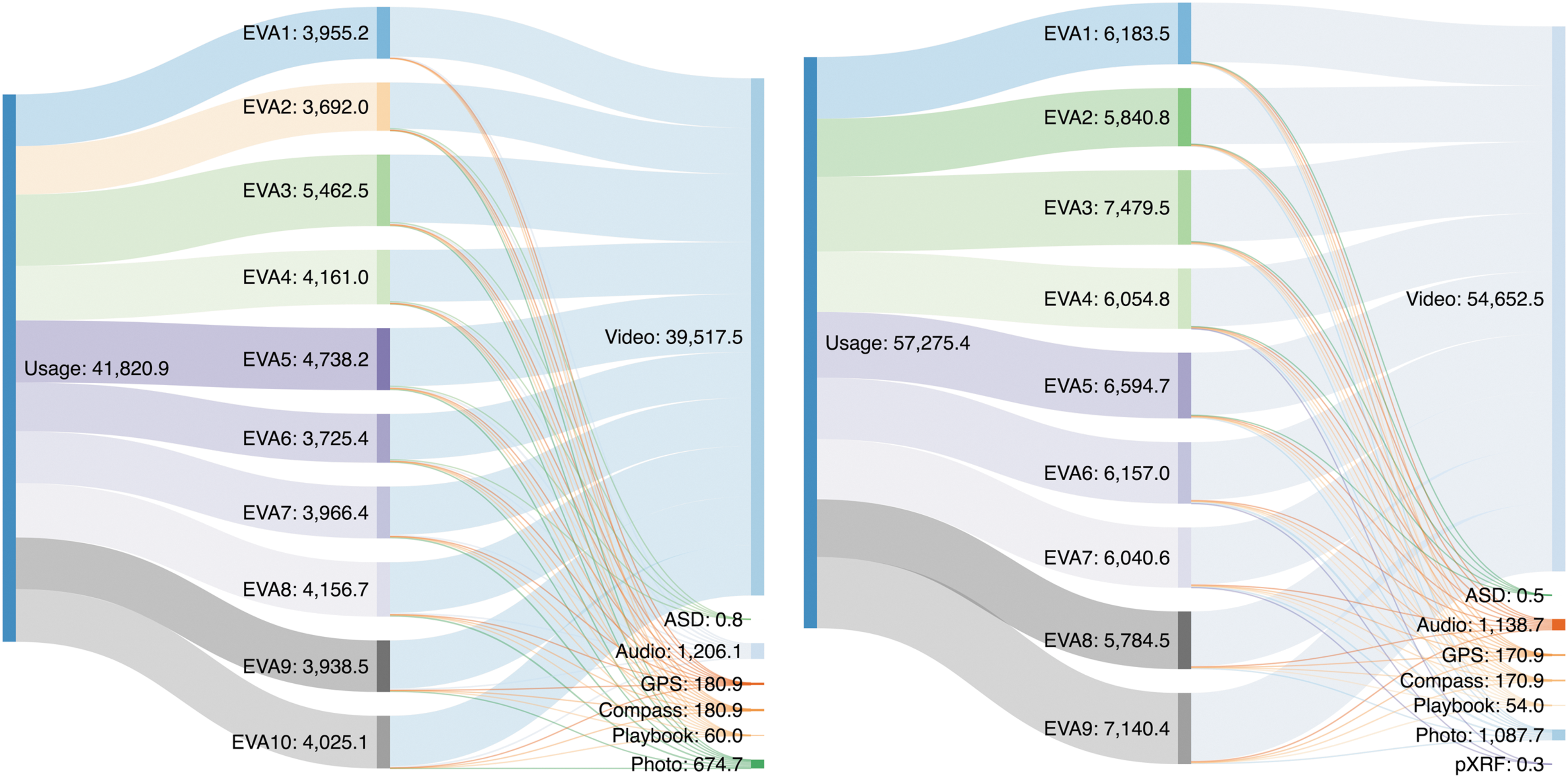
The data from Table 1 are shown graphically in Fig. 14 for BASALT-1 (Idaho 2016) and BASALT-2 (Hawai‘i 2016). The vast majority of all data transmitted for both expeditions was video data, which uses approximately 95% of the total bandwidth. Audio data imposed the second largest data demand, although for the BASALT-2 Hawai‘i expedition, still camera images were equivalent in data volume to the audio.
(
Figure 15 shows the data usage for each deployment; data usage in megabytes is shown on the y axis, and the EVA day number is shown on the x axis. This shows the daily data usage totals shown in the rightmost column of Table 1 in bar graph format and sums these values over the length of each expedition, shown by the points. A linear regression is plotted over the cumulative sums of data usage. The daily data usage was higher for each EVA day for the BASALT-2 (Hawai‘i 2016) deployment as compared to the BASALT-1 (Idaho 2016) deployment. This could be because the BASALT-1 (Idaho 2016) deployment in Idaho experienced more issues with video streaming and on average had shorter EVAs, both of which resulted in reduced video data transmitted for BASALT-1. For the BASALT-1 Idaho deployment, a linear fit of y = 4221.7x + 70.55 (R 2 = 0.9985) was found, and for the BASALT-2 Hawai‘i deployment, a linear fit of y = 6352.4x − 40.652 (R 2 = 0.9994) was found. These linear regressions constrain potential data usage estimates over the length of a human exploration mission for a given number of EVA days of similar EVA objectives, thereby aiding communication planning for exploration mission concepts.
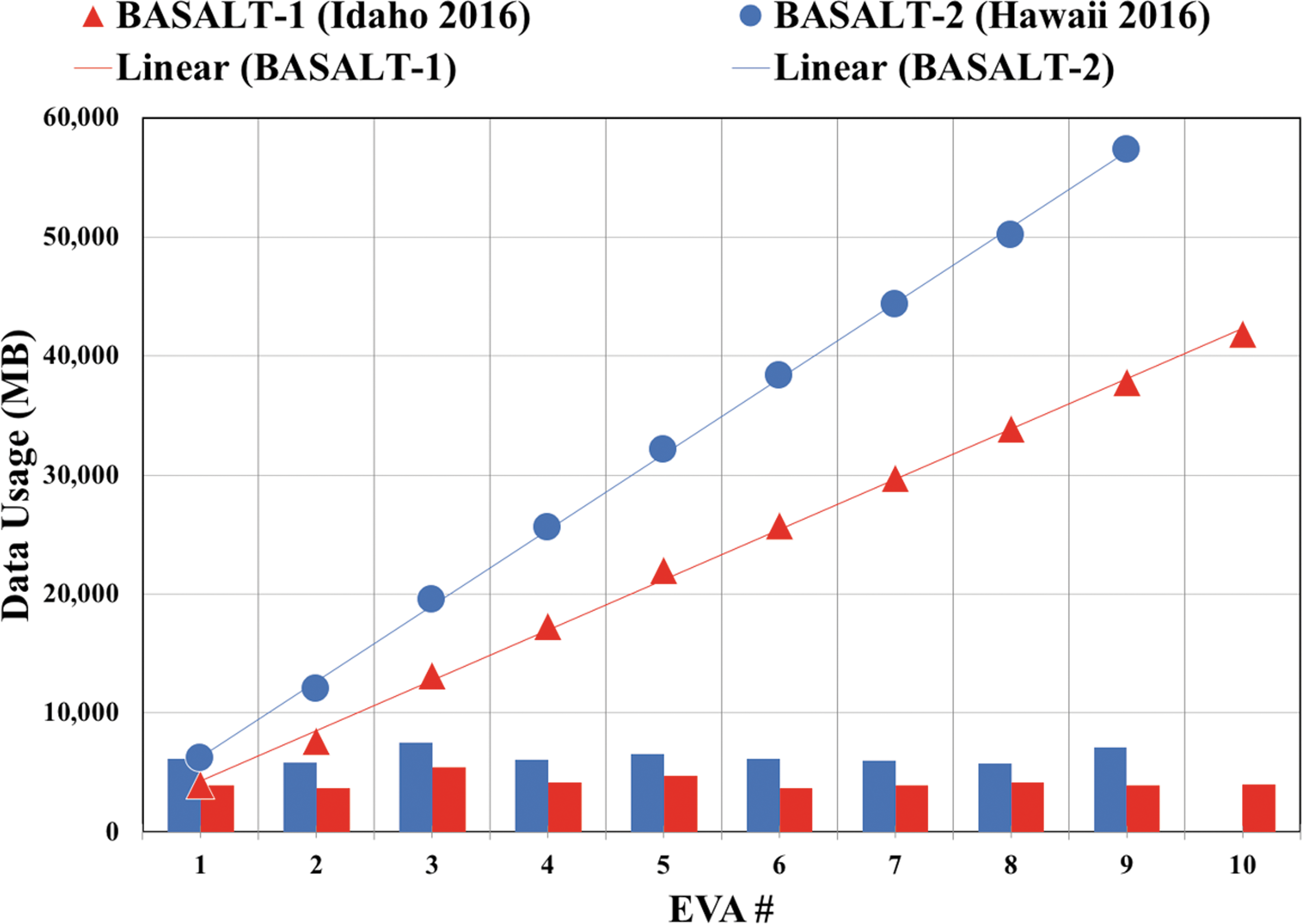
Data usage for the BASALT-1 (Idaho 2016) (red) and BASALT-2 (Hawai‘i 2016) (blue) expeditions. The bar graph at the bottom shows daily data usage sums, while the data points show the cumulative data usage, with a linear regression overlaid, all in megabytes.
4. Discussion
A robust telecommunication architecture is one of the pillars of a successful mission. With the BASALT field campaign, the team simulated the primary data sources for a human science-driven mission to Mars to understand how effectively this architecture can support the real-time demands imposed by a full EV, IV, and MSC team (Lim et al., 2019). Data utilization analyses provide an explanation of how the total bandwidth was utilized by each data product type. These data are valuable because they show the data products required by the science team to guide the EV crew members and collect valuable scientific measurements on the sample areas without the experts being in the field to survey and collect the samples themselves (Kobs Nawotniak et al., 2019). The subsequent sections discuss the primary design challenges faced by the telecommunications team along with a short narrative explaining the relevancy of the data analysis provided in Section 3 to the planning of human planetary telecommunications architecture.
4.1. Challenges and benefits of using COTS hardware for the EVIB
Using COTS products allowed the telecommunications team to construct a working system in a relatively short time compared to designing custom components for each subsystem. Most devices used common standards such as IEEE 802.3 Ethernet Protocol, so the data connections between devices required minimal custom hardware dedicated to standards or format conversions. One design parameter that was not met for all hardware was the operating temperature range of a few devices. The high ambient summer temperature in Idaho coupled with the heat generated by the hardware inside the EVIB led to a few failures during the first field deployment. The telecommunications team had enough spare parts to keep the EVIB systems running for the duration of the field test and came up with creative strategies to mitigate some of the heat (e.g., utilizing heat sinks with a conductive cooling solution). But overall, by not designing a custom system with the appropriate thermal tolerances, the EVIB were not fully functional for the entire mission.
The headsets needed a better overall fit and a significantly improved noise-cancelling microphone. Better-quality connectors also needed to be budgeted for and used in the future for all exterior bulkhead connections, as failures arose after the BASALT-2 field test. Management of the wrist display became cumbersome during rainy days since it was not waterproof. EV crew members either kept them in a resealable plastic zipper storage bag tucked in their pocket or under a rain jacket sleeve. Having a waterproof device, or a device in a waterproof case that could still be worn on the wrist, would be greatly beneficial.
Designing hardware and software that could natively handle the delay seen on a long-distance link, as with Earth to Mars, would be more flightlike. A delay emulator could be added to the network and allow configuration of packet loss, bandwidth limits, jitter, packet duplication, corruption, re-ordering, and most importantly, long delays. Instead of each system and software suite inserting their own delay, all systems would experience the same delay.
Another important step for the advancement of this analog program would be to use Disruption Tolerant Networking, or DTN, which ensures data delivery to the destination by storing it until the connection is available. This technology will be a requirement by the time that humans are sent to explore Mars and will be part of NASA's Space Communication and Navigation (SCaN) space inter-networking architecture (NASA, 2014).
4.2. Development milestones of deploying hardware in an analog environment
A significant amount of planning was required to successfully execute the remote field deployments for the BASALT program. The planning process began by having capability requirements discussions with the Mission Management Team, closely followed by a recon trip to the field site. The two most important factors considered by the telecommunication team during planning were (1) the geographical location of the MSC and field sites and (2) the communication capabilities needed by the field team.
The high-level requirements for developing the new EVIB for the BASALT project were primarily derived from inputs by the science and exploration researchers. However, in addition to the new requirements, at least 50% of the previous primary hardware components had to be reused to stay within the allocated budget. Because of the unplanned redesign of the backpacks (instead of reusing existing backpacks from past analogs, as originally proposed), the schedule and budgetary constraints posed significant challenges. Existing EVIB from a previous project had to be redesigned to provide greater subject mobility, reduce fatigue resulting from extended (5–8 h) usage, and improve the internal component layout to accommodate new hardware capabilities. The telecommunications team was able to develop a design that fulfilled the requirements and met the schedule for design, prototype, and final delivery.
In a future flight mission, the S/A camera will likely be attached to a rover or other robotic vehicle that will follow the crew members during EVA. To simulate this function, the telecommunications team had to task one member of the field team with carrying, moving, and aiming the S/A camera to follow the EV crew members while on EVA. Similar to the S/A camera, the “In-Field Comms Leader” had the primary job of carrying a set of the meshing radios to act as a relay between the Central Relay Node and the EVIB. During the mission, it was necessary for this person to actively seek out ridges and other high spots that permitted line of sight to both the Central Relay Node, EVIB, and S/A camera, while staying out of any potential science sample sites. The ability of the S/A camera to follow the EV crew members, and the ability of the telecommunications relay to maintain line of sight between the crew members and the Central Relay Node, were viewed as necessary for future human exploration missions (Beaton et al., 2019). For a flight mission, S/A camera implementation needs to carefully consider minimizing the hands-on time required by astronauts to position these assets.
4.3. Data utilization and the effect on future human spaceflight telecommunications development
While several of the data products were captured wirelessly within the telecommunication architecture, other data products were not and still need to be considered for a complete understanding of bandwidth requirements. The BASALT program did not have any rovers, habitats, or landers in this mission; therefore, any system data products required for those mission elements are an area of future work. These data include but are not limited to vehicle state of health, position, audio, imagery, and housekeeping telemetry from onboard systems. The system health of the EVIB was not monitored during the mission. Additionally, BASALT focused on the Intra-EVA portion of the mission, which means the bandwidth requirements during the non-EVA portions of each mission day were not studied or captured.
The network data demand demonstrated from BASALT, especially the observation that video consumed 95% of the data bandwidth, suggests that the current Deep Space Network architecture for Mars must evolve to support the higher bandwidth requirements of human exploration missions, especially if live streaming video is a requirement. Seibert et al. (2019) outline the current upgrade plans for the Mars telecommunication architecture. Further effort should also be devoted to investigating the optimal streaming video frame rate, resolution, and compression algorithms to ensure adequate scientific data return while making efficient use of network bandwidth. Studying the tradeoffs between various video options, including supplementing video with still images of varying file sizes, will help determine the true bandwidth needed for imagery. For example, if lower resolution or frame-rate video are acceptable when augmented with a few higher-resolution images, this could save substantial overall Intra-EVA bandwidth. As indicated by Beaton et al. (2019), video provided valuable S/A to the remote scientists in the MSC, so the BASALT team expects that efforts to improve its bandwidth utilization efficiency, while still delivering the required S/A, will prove worthwhile.
5. Conclusion
Overall, the telecommunications team successfully achieved its primary goal of enabling the exploration and science researchers to complete their goals through providing proto-flight telecommunications infrastructure and EVIB along with bandwidth collection tools required to complete postmission analysis of data products. This bandwidth utilization data proved to be valuable in evaluating effectiveness of a particular technology (science instrument or imaging source) for a given amount of bandwidth by allowing the scientists to gauge how a given measurement source aided in selecting sampling locations.
The origination of the telecommunications infrastructure and its constituent elements (including the EVIB and S/A camera), along with the implementation process, requisite operations, and data analytics, illustrate the level of effort needed to execute a combined science and exploration analog mission. This project has revealed areas where taking smaller risks to advance current technology can be beneficial for the exploration community. An example of this was integrating a new COTS meshing radio system into the EVIB and observing the performance relative to previous hardware. Leveraging partnerships with academia and industry will also help foster development and provide a platform for up-and-coming technologies to be tested against flightlike mission constraints, especially within the EVIB systems.
This team will continue to work with the NASA Human Spaceflight Architecture Teams to provide data on bandwidth requirements and what telecommunication architectures have proven to provide the greatest flexibility and reliability under simulated mission conditions. These agency-level teams will use our data to refine the flight architecture, specifically for the Intra-EVA phase of the exploration. In turn, the telecommunications team will continue to evolve our designs to reflect the current thinking of the mission planning teams, and keep the cyclic approach so that the two groups move closer to a realistic and proven communications architecture that works for the scientists using the infrastructure as well as the engineers designing the systems.
Footnotes
Acknowledgments
The authors would like to thank the NASA Planetary Science and Technology Through Analog Research (PSTAR) Program (NNH14ZDA001N-PSTAR) grant (14-PSTAR14_2-0007) to D.S.S. Lim, with additional support from NASA SSERVI FINESSE grant to J. Heldmann. We would also like to thank the community of Arco, Idaho, and the staff at both Craters of the Moon National Monument and Preserve (Idaho). We are also grateful for the support provided by Hawai‘i Volcanoes National Park (Hawai‘i), USGS Hawai‘i Volcanoes Observatory (HVO), and Kilauea Military Camp (Hawai‘i). The science operations research conducted during BASALT deployments was approved through the NASA Johnson Space Center Institutional Review Board (IRB) (Protocol ID 2202). This is BASALT publication number BASALT-2018-009.
Author Disclosure Statement
No competing financial interests exist.
1
TRL is a measurement scale developed by the United States Government to assess the maturity level of a technology. The scale ranges from one to nine where a Level 1 is denoted for a new scientific principle observed or reported, and Level 9 is an actual system “flight proven” through successful mission operations (NASA, ![]() ).
).
2
Mission Workshop can be found at