
Abstract
Metalworking fluids have the ability to extend cutting tool life and improve the machinability of materials. There is a need for the development of reliable machining tests which can be used to screen fluids with high confidence to allow for ranking in terms of performance. This study developed a novel methodology utilizing single-point milling to evaluate fluid performance in terms of tool wear and cutting forces across various aerospace alloys. The repeatability of the procedure was assessed and demonstrated by using standard deviation. The study showed alternative cutting fluid compositions could influence tool life performance across all the aerospace material variants. Inconel 718 was shown to be the hardest material to machine followed by Titanium Ti–5Al–5Mo–5V–3Cr and Titanium Ti–6Al–4V. However, with each material, there was a differentiation in fluid performance with up to 11% difference in average tool life between different fluids.
Keywords
Introduction
Metal cutting processes such as milling, turning and drilling account for a large proportion of the cost of high-precision part production. However, these processes remain popular, as they outperform competing manufacturing operations at creating the surface quality and dimensional accuracy which are demanded by designers and customers. To consistently achieve product requirements the machining process parameters and cutting tool conditions should be carefully monitored as the extreme tribological contact conditions found in machining can lead to significant tool wear, thermal expansion and contraction of parts and unwanted near-surface work hardening of the workpiece [1].
To reduce the severity of the contact conditions in metal cutting, metalworking fluids (MWFs) are used to reduce friction, evacuate chips from the cutting zone and remove heat from the system [2]. MWFs are designed with specific compositions of oils (mineral and synthetic) and specialty additives. These formulations enhance the fluids’ ability to reduce friction in the contact zone by forming a tribofilm layer, separating the asperities on the surface of the sliding contacts via fluid entrainment and chemophysical interaction of additives.
Due to the hybrid polycrystalline microstructure of metals and the defects in structure, the free surface energy and ability for additives to bind to the surface greatly varies depending on the material, surface treatment and surface topography [3]. This means there is a large difference between the tribochemistry of different materials and grain structures of the contacting surfaces. Cutting parameters will also have a marked effect on the tribology of the contact area. As the cutting speed increases the coefficient of friction reduces, and temperature and pressure will activate certain additives [4]. Previous studies have demonstrated that extreme pressure (EP) additives containing phosphorus or sulphur can impact tool life during the machining of aerospace alloys [5]. The diversity of MWF products means that it is crucial to have the ability to differentiate the influence of fluid additives on performance over a range of materials and cutting parameters during machining, using a test methodology that is applicable to industry.
In most sciences replicable, widely applicable, and repeatable testing methods are refined to produce standardized testing techniques [6]. Due to the nature of machining, the underlying phenomena are complicated and difficult to measure. This leads to macro-level studies being conducted at an industrial-size scale with disputed theories and a potentially high cost of validation. Existing methodologies utilized to test the performance of MWFs are often unique and no standardized test is available, making it difficult to compare data from different studies [7]. Industrially accepted testing methods such as ‘ISO8688-1989 – Tool life testing in milling, part 2: end milling’ are in need of review considering current technological capabilities and theory [8].
Benchtop tribometers such as reciprocating wear and four ball tests are typically used to assess the tribological behaviour of MWFs [9]. By measuring friction trends the fluids can be ranked [10]. The aim of these systems is to replicate the testing conditions found in machining applications, providing a cost-effective methodology with high repeatability. However, shortcomings of these testing systems include the inability to replicate extreme conditions and realistic interactions found within actual metal cutting, such as severe plastic deformation and high-speed contact at interfaces [11].
Previously, a simplified milling test was used to compare the machinability of various steel materials through monitoring tool wear. The study demonstrated the ability and cost-effectiveness of using a single cutting insert for milling trials to compare machinability when using different cutting configurations [12]. Other publications detail how to document the workpiece material information and how to measure the progression of tool wear over time [8]. However previous work did not discuss tool wear methods in milling that ensure resource efficiency and experimental control. Fluid maintenance or the tool path to follow for each cut was not specified.
The authors’ previous work [13] developed an enhanced single-point milling (SPM) methodology as a simplified laboratory-style machining performance test aiming to fill the gap between tribometer tests and application machining tests. This methodology allowed the comparison and selection of MWFs for specific industrial applications. The current study is an evolution of the previous work which requires less tool life trials per fluid/material combination, allowing the tests to be more efficient with time and cost. Additional workpiece material options have been included alongside rigid controls on test variables such as sump MWF levels and tramp oil levels. Additional quantitative performance comparison includes the application of standard deviation (SD) and cutting force comparisons.
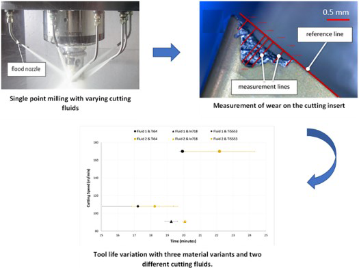
This study further develops a novel SPM test procedure which allows MWFs (coolants) to be screened and ranked in terms of performance. This test methodology aims to assess fluid performance by monitoring tool life via tool wear during the machining of common aerospace alloys. Demonstrated in this study is the milling of Inconel 718 (In718), Ti–6Al–4V (Ti64) and Ti–5Al–5Mo–5V–3Cr (Ti5553). Ti5553, a beta titanium alloy, is used within the aerospace sector due to its high strength and fracture toughness. Arrazola et al. [14] demonstrated the low machinability of Ti5553 in comparison to a common aerospace alloy Ti64, where 25–50% higher cutting forces were measured. The difficulties associated with machining titanium such as its low thermal conductivity and premature tool wear due to high chemical affinity to the surface treatments applied to cutting tools are well known [15]. The increased difficulty in the machining of Ti5553 was believed due to its higher strength and hot hardness combined with eight times the molybdenum equivalency in comparison to Ti64 [14].
Experimental work
Milling is deemed to account for a large percentage of metal machining operations and is shown to be sensitive to the choice of coolant due to the intermittent tool engagement [16]. This SPM methodology utilizes a short, stiff milling tool holder running at low depths of cut with little material consumption. The use of a single cutting edge or ‘tooth’ reduces the probability of tool chatter (excess vibration) and eliminates any runout variation which could occur from tooth to tooth [12]. It also reduces the complexity of the system, such as how the wear effect on one tooth increases the loading on the subsequent tooth to enter the cut.
Trials configuration
The machine tool used was a three-axis vertical CNC machine, a DMG Mori Seiki NVX5080. The machine tool was fitted with an ‘IFDR’ filtration system which supplied external flood coolant, which filtered metallic particulates and removed tramp oil. Machining involved a shoulder milling process, down milling (climb milling) at 2 mm axial and 2 mm radial depths of cut, with a feed rate of 0.11 mm tooth−1 and with one insert in the holder. The tool performed a straight-line cut through the work material. Following common practice for hard-to-cut alloys, the tool entered the cutting pass in an arc to control chip form and cutting forces on entry. Surface speeds were dependent on the workpiece machined – for Ti64: 170 m min−1, Ti5553: 108 m min−1 and In718: 91 m min−1, with the speed selected after screening trials and the aim is to achieve a tool life of 20 minutes using a reference MWF. These surface speeds were utilized when machining with two different MWFs, and the time to achieve a predetermined level of tool flank wear was monitored and compared to the target 20 minutes achieved with the reference fluid. The link between increasing machining productivity and increasing tool wear rates has been extensively shown with an example being [12]. A tool life of around 20 minutes is recommended by cutting insert manufacturers in order to strike a balance between utilizing too much machine and operator time at lower rates of productivity and wearing out too many tools at higher productivity rates.
A single type of Seco Tools’ coated cemented carbide ‘turbo’ cutting insert (type XOEX120408R – M07 MS2050) was used with the different work material variants. The milling inserts used had a cemented tungsten carbide substrate with a titanium aluminium nitride pressure vapour deposited (PVD) coating. Inserts had an axial rake angle of 8°, radial rake angle of 5.8°, helix angle of 15°, and a corner radius of 0.8 mm. This type of insert was selected as carbide-based nitride-coated tools with this type of cutting geometry are representative of a large proportion of the milling tool options used on heat-resistant super-alloys, so these inserts represent a low-cost sensible ‘Pareto’ type choice. A 50 mm diameter milling tool holder (Figure 1(a)) was utilized which supplied coolant through the holder body (known as ‘through-tool’ or TT) and then out through three fixed nozzles of approximately 1 mm exit diameter, aimed at the milling insert's rake face. Fluid was also supplied to the cutting zone via external flood nozzles as per Figure 1(b).
Experimental set up of the DMG Mori Seiki NVX5080: (a) tool holder and cutting insert set up in the machine spindle, (b) external flooding of cutting insert during machining using nozzles.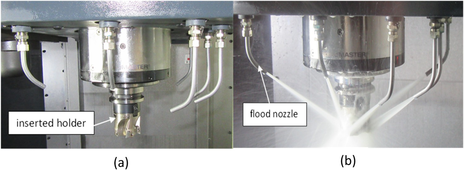
To ensure fluid performance differentiation in terms of tool wear in comparison to the reference fluid, the following experimental methodology was utilized throughout the trials. Four repeat tool life tests were run at the reference surface speed per fluid and per work material, until tool failure had occurred in each case.
Nominal chemical composition of In718.
Nominal chemical composition of In718.

Nominal chemical composition of Ti64.

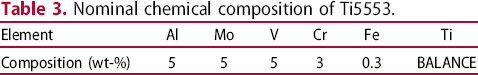
Nominal chemical composition of Ti5553.
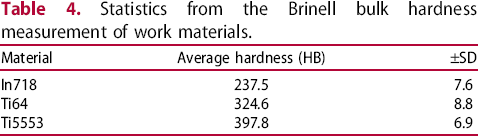
Statistics from the Brinell bulk hardness measurement of work materials.
Two MWFs were tested within this project. Fluid 1 was a commercially available aerospace MWF and was used as a suitable benchmark reference fluid. Fluid 2 was a competitive commercial fully formulated MWF. This work has been disseminated for research purposes rather than commercial purposes, so product names are not used. Further details of the fluid formulations are provided below.
Fluid 1 – this is a fully formulated benchmark commercial fluid; a high-lubricity product containing mineral oil and considered well-suited to hard-to-cut alloys. Fluid 2 – alternative fully formulated commercial fluid from a different supplier; vegetable-based and with low hydrocarbon content, this is a contrasting product to the benchmark in terms of formulation so was expected to provide a counterpoint in performance terms. Fluid 2 is also said to perform well when processing hard-to-cut alloys.
Fluids were supplied in two 20 L pails each, which were diluted on site to give 10 vol.-% oil-in-water emulsions. Pressure gauges indicated that the TT MWF pressure was 30 bar. The total MWF flow rate (TT plus flood) was 66 ± 2 L per minute.
Tool life testing
An ISM-PM200 digital toolmaker's microscope with a stand was used for measuring flank wear on the cutting tool inserts as shown in Figure 2(a). The microscope was calibrated using a graticule when the magnification was adjusted and when the device was first used. The milling tool assembly was removed entirely from the machine tool spindle or carousel and placed into a jig with the axis orientated horizontally to allow ease of rotation when placing the tool under the microscope. The cutting edge to be inspected was cleaned beforehand with a cloth to remove any MWF and swarf.
(a) ISM-PM200 digital microscope set up to take cutting insert flank wear images and (b) example of where tool wear measurements were taken on the flank face of the cutting region of the insert.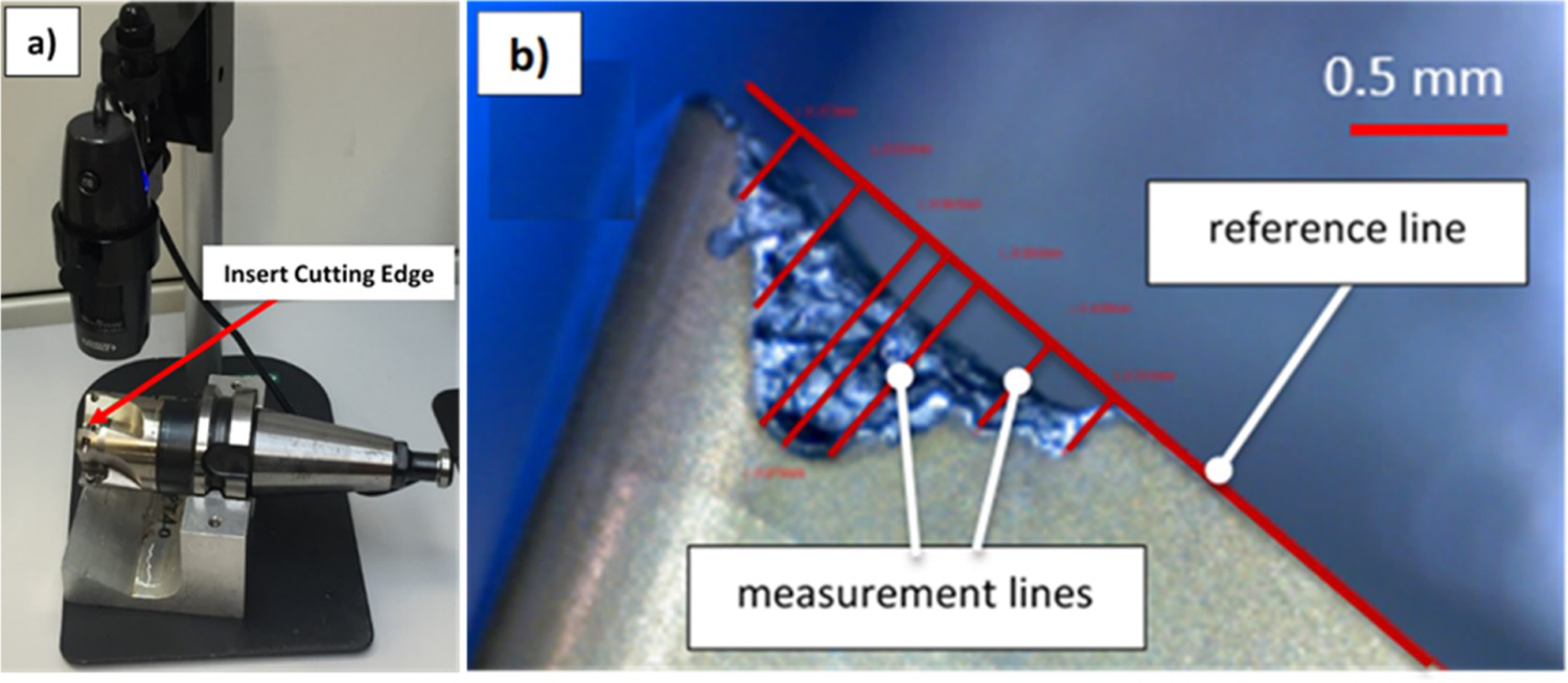
Wear was measured on the flank face of the cutting region after a specific number of milling time intervals (Figure 2(b)). These measurements focused on the corner radius feature of the tooling insert. This region was in cutting contact and was therefore the area of interest. The cutting time intervals were usually equal to the time taken to cut a full length of the block, which varied between 1 and 4.5 minutes. To save testing time once approximate tool lifetimes had been established for a particular combination of surface speed and alloy, each tool life test was run uninterrupted for 14 minutes. Tool wear was then measured regularly after each complete pass, and this was repeated until the test ended based on the average measured flank wear being equal to 0.25 mm. This limit was selected as a level beyond which the quality of the machining process started to suffer due to increased cutting forces and the tool wear rate beginning to accelerate towards eventual fracture.
A Kistler 9139AA plate dynamometer was used for this study. The dynamometer was bolted onto the machine table with plastic sheeting placed over it to minimize any MWF getting into the instrument and affecting the sensors.
Cutting force tests were performed for each of the three alloys tested using Fluid 1 during tool life trials. Whilst tool wear was measured after a set number of passes, cutting forces were measured during the whole of a cutting pass. Forces were measured for the tool in the new condition (pass 1). Kistler DynoWare software was used for data acquisition and subsequent data analysis. The key aspect for force data acquisition was to analyse the mean resultant forces in the steady-state milling condition, where the tool was fully engaged with the work material and where forces had stabilized. Mean forces in X, Y and Z directions were measured over a period of 10 steady-state tooth passes, then the mean background (non-cutting) force for this period was subtracted to calculate the mean cutting forces in X, Y and Z. The resultant force was then calculated. The background ‘zero’ force was measured in between engagements of the milling tooth. A high force sampling frequency of 5 kHz was used, based on the tooth pass frequency and low radial immersion in this trial set up.
Experimental control methods
Cutting tool inspection
Previous work indicated that the condition of supply of the cutting inserts could differ significantly between or within batches. It was shown that this affects cutting forces and tool life and it is therefore important to check the condition of supply [17]. An Alicona SL high-resolution 3D imaging system was used to check the condition of supply of the inserts and to eliminate any anomalous cutting edges.
Tramp oil contamination
The NVX5080 machine releases hydraulic lubrication oil at a high rate during machining. This is an intentional feature of the machine, implemented to ensure long-term reliability. If this lubrication oil enters the machine tool sump (known as the ‘tramp oil’ effect) the performance of the MWF can be measurably enhanced in terms of tool wear rates which is a potential confounding effect for tool life testing [18,19]. Three steps were taken to control tramp oil. A coolant separation tank which collected contaminating lubricating oil and MWF from under the machine slideways and was identified as a route for tramp oil contamination into the sump was removed. This was followed by retrofitting an IFDR300 filtration system which utilized a weir system to remove tramp oil. This was combined with a see-through separator which is also capable of capturing tramp oil [20].
MWF concentration
MWFs are tailored to work within a specific concentration range. This range is determined by the manufacturer for optimal performance to assure product quality and longevity, as well as for health and safety reasons [21]. Bulk MWF concentration was measured twice daily using a Hanna HI 96801 digital refractometer to ensure that the concentration was maintained at (10 ± 0.5)%.
Sump level
During preliminary machining, higher-than-range concentration and low sump fluid volume levels were observed due to water loss. To continuously monitor the sump level an LVCN414 series non-contact ultrasonic level controller and transmitter was utilized. The LVCN414 gives a resolution of 0.5 mm and an accuracy of 3 mm. Level indication was monitored via a local display. A level sensor was positioned at the top of the tank and utilized ultrasonic pulses. The pulses transmitted from the sensor reflected off the top surface of the fluid media and back to the sensor. The time it took for the signal to return to the sensor was used to measure the position of the fluid's surface. The level of MWF in the machine sump was sampled every 15 minutes using the level sensor and when the sump level needed to be corrected, the refractometer was used to simultaneously control concentration.
Sump temperature
The MWF temperature in the sump was monitored using a type K thermocouple probe. One measurement was taken every 2 minutes. With a temperature range between −50°C and 450°C and ±1.5°C accuracy, the probe had the adequate ability to monitor changes to coolant temperature. The thermocouple was connected to a data logger.
Results
Tool life curves
Milling insert tool life was evaluated at a range of surface speeds with the three alloy material variants for the baseline commercial MWF (Fluid 1). The initial aim was to determine machining surface speeds for all material variants that would achieve (a) 15 then (b) 25 minutes of tool life. This firstly involved milling for 25 minutes at between four and seven different surface speeds, starting at a low speed, with tool wear being measured only once after 25 minutes’ cutting. The target in these tests was to achieve 0.25 mm (VB) average tool flank wear within this time limit. Once the surface speed corresponding to 25 minutes’ tool life was established, milling was run for 15 minutes at between four and seven slightly higher surface speeds with tool wear measured once after 15 minutes’ cutting. The target in these tests was to achieve 0.25 mm average wear after 15 minutes, so a higher surface speed was required for a higher tool wear rate.
After ascertaining the appropriate surface speeds for 15 and 25 minutes’ tool life with Fluid 1, a linear tool life curve was plotted to interpolate and approximately predict the surface speed corresponding to 20 minutes’ tool life (known as V20). Four repeat tool life tests were run at the interpolated surface speed, still using Fluid 1. It was checked that the mean tool life was as expected, with a target of 20 minutes.
Alloy Ti64
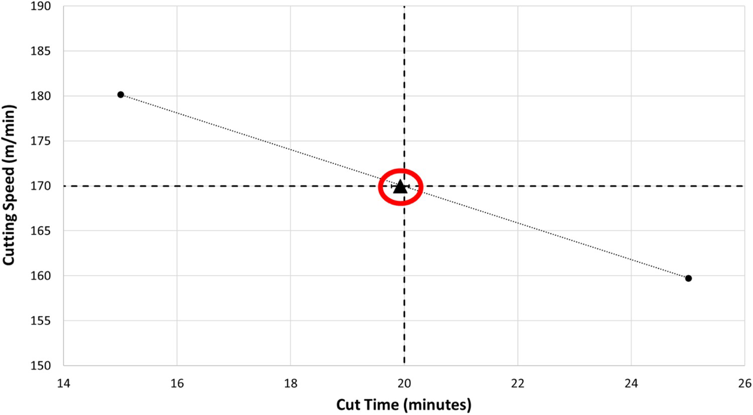
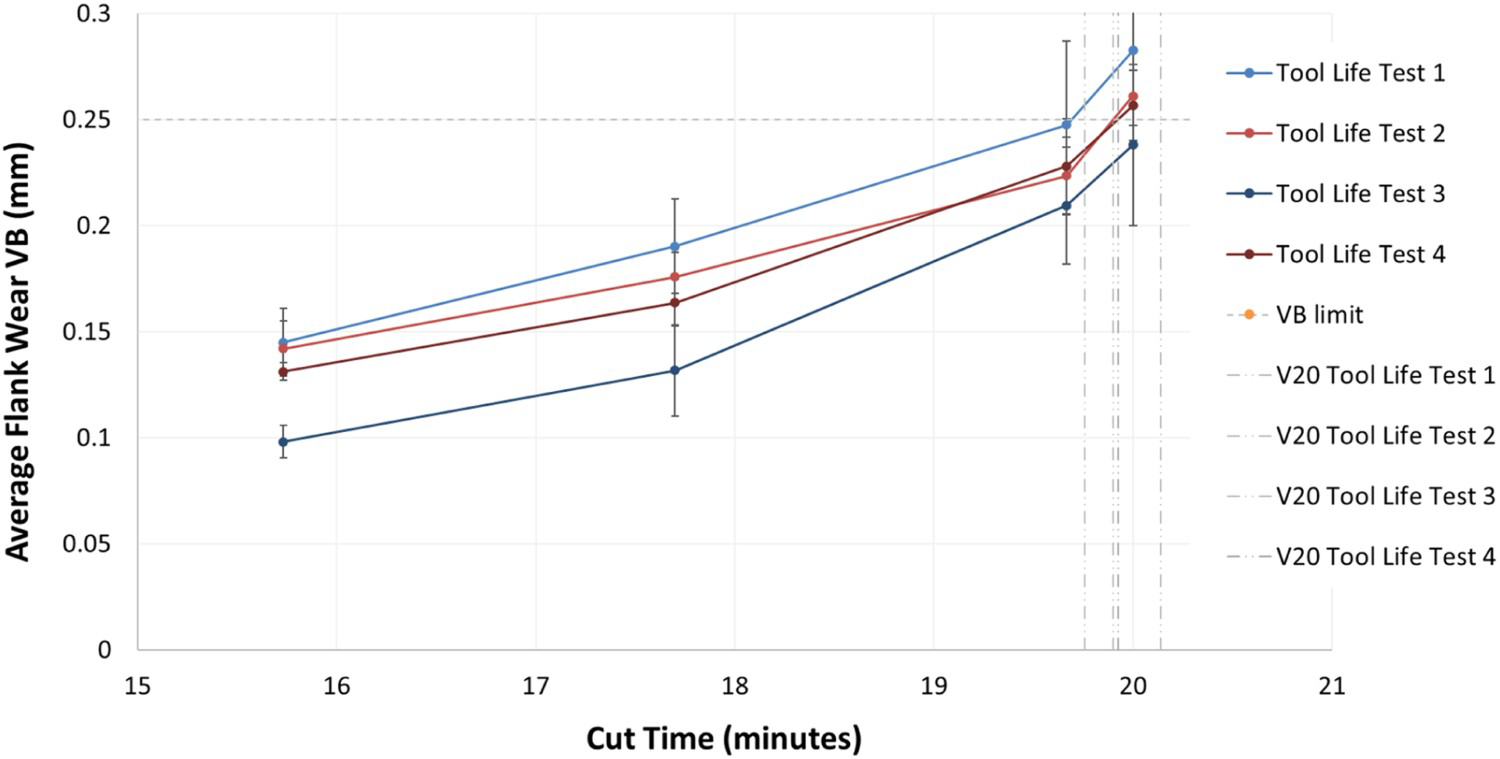
For the Ti64 material with the baseline fluid (Fluid 1) four cutting speeds from 155 to 160 m min−1 were utilized to achieve a tool life of 25 minutes, and higher cutting speeds of 179–188 m min−1 were run to achieve 15 minutes, both with an average tool flank wear of 0.25 mm (VB) (Figure 3). A cutting speed of 180 m min−1 achieved a 15-minute tool life and a cutting speed of 160 m min−1 achieved 25 minutes. From the graph (Figure 4), the cutting speed to achieve a 20-minute tool life was interpolated at 170 m min−1. Four repeat tool life tests were carried out (Figure 5) at this selected cutting speed and the mean tool life achieved was 19.9 minutes (highlighted in Figure 4), extremely close to the target of 20 minutes. Measures used to assess the variability of multiple test results around the mean are the standard deviation (SD) and the 95% confidence interval (the CI). The error bars featured in the plots which are to follow are illustrating the CI for the data.
Results of tool wear tests for Ti64 with Fluid 1, used to identify V15 and V25 surface speeds. Non-filled plot point represents an anomalous result. Tool wear data for Ti64 with Fluid 1: V15 and V25 data are plotted and V20 cutting speed was interpolated. Progressive tool wear data for Fluid 1 and Ti64 highlighting four repeat tool life tests. Error bars represent the 95% CI from seven measurements taken across the width of the flank wear scar.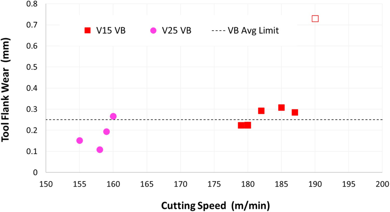
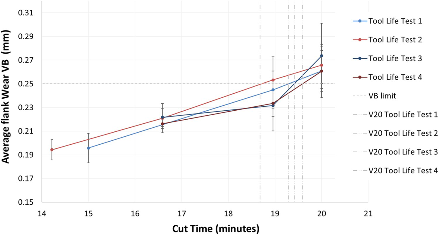
With In718 being a harder material to machine than Ti64, lower cutting speeds were utilized for testing. Four speeds between 90 and 105 m min−1 were utilized to achieve 15 minutes’ tool life and lower speeds between 85 and 90 m min−1 were used to achieve a 25-minute tool life. Figure 6 highlights that 15 and 25 minutes of tool life were achieved via cutting speeds of 96 and 87 m min−1 respectively. By interpolating this data, a cutting speed of 91 m min−1 was selected to achieve a tool life of 20 minutes. Four repeat tool life tests were carried out (Figure 7) at this selected cutting speed and the mean tool life achieved was 19.2 minutes as highlighted in Figure 6 – close to the targeted 20 minutes.
Tool wear data for In718 with Fluid 1: V15 and V25 data are plotted and V20 cutting speed was interpolated. Progressive tool wear data for Fluid 1 and In718. Four repeat tool life tests. Error bars represent the 95% CI from seven measurements taken across the width of the flank wear scar.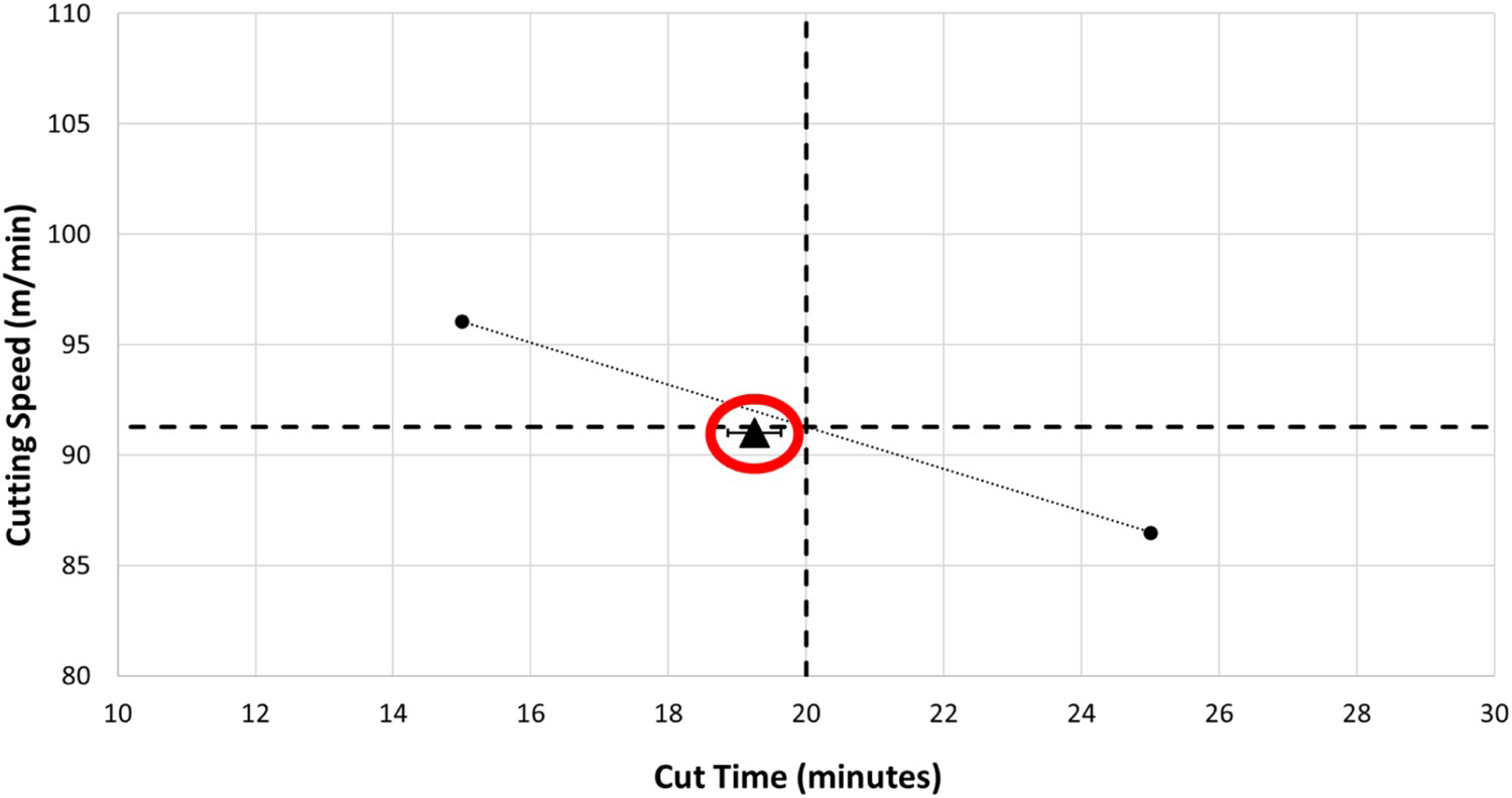
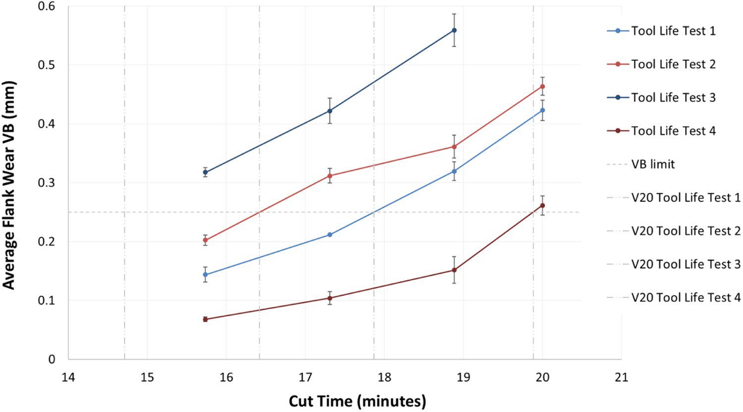
Four speeds between 110 and 125 m min−1 were utilized to achieve 15 minutes’ tool life and lower speeds between 80 and 105 m min−1 were used to achieve a 25-minute tool life. Figure 8 highlights how 15 and 25 minutes tool life were achieved by cutting speeds of 115 and 101 m min−1 respectively. By interpolating this data, a cutting speed of 108 m min−1 was selected to achieve a tool life of 20 minutes. Four repeat tool life tests were carried out (Figure 9) at this selected cutting speed and the mean tool life achieved was 17.2 minutes, highlighted in Figure 8. Compared to the other two material variants the repeatability of tool life was lower for Ti5553 and as can be seen there is a larger variation between the four wear curves.
Tool wear data for Ti5553 with Fluid 1: V15 and V25 data are plotted and V20 cutting speed was interpolated. Progressive tool wear data for Fluid 1 and Ti5553. Four repeat tool life tests. Error bars represent the 95% CI from seven measurements taken across the width of the flank wear scar.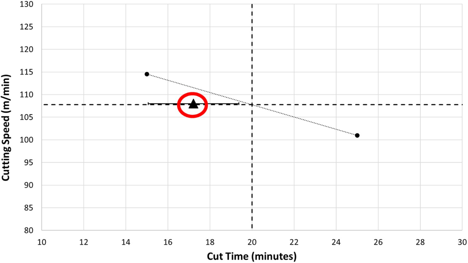
Introducing the second fluid tested, Figure 10 presents the tool life and cutting speed data for the reference fluid (Fluid 1) and for Fluid 2, for all three alloy material variants. The machining parameters for each alloy variant to achieve 20-minute tool life, as selected in Section 3.1, were utilized for the second fluid providing a means to compare the performance of the two fluids. As with Fluid 1, four nominally identical tool life tests were performed with Fluid 2 for the three alloy variants.
Summary of tool life testing data for three alloys and Fluids 1 and 2. Four repeat tool life tests for each fluid/alloy combination. Averages (markers) shown. Error bars represent the 95% CI based on four repeat tool life tests.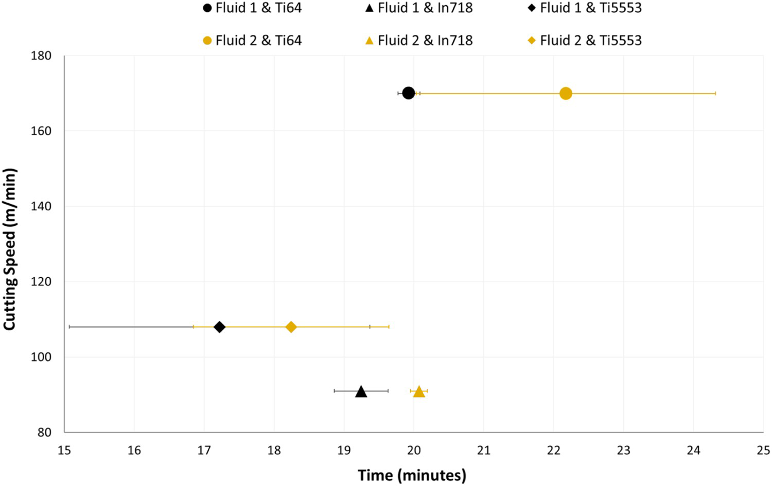
Figure 10 illustrates the differentiation in tool life during the machining of Ti64 with the two MWFs. With the reference fluid (Fluid 1) the average tool life was 19.9 minutes, whereas with Fluid 2 the tool life extended to 22.2 minutes (11.6% increase) on average at the same machining parameters. Similar trends were observed with Ti5553 where Fluid 2 was the better-performing fluid with an average tool life of 18.2 minutes (5.8% increase) in comparison to 17.2 minutes with Fluid 1. With In718, Figure 10 furthermore shows that Fluid 1 achieved 19.2 minutes of tool life on average whereas lower tool wear rates were observed with Fluid 2 which achieved a tool life of 20.1 minutes (4.7% increase).
Summary of experimental tool life data for Fluid 1 and Fluid 2.
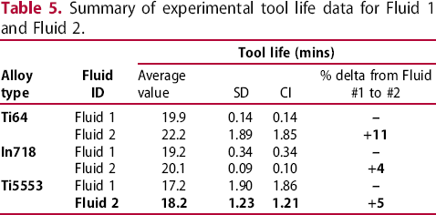
Figure 11 captures tool wear occurring after 16 minutes’ machining of the three alloy material variants with the two fluids. As already identified, the tools wore quicker with the application of Fluid 1. For Ti64 (Figure 11(a)), with both fluids, the cutting edge has an appearance at the contact zone which is much shinier than either the tool coating or substrate, indicating that alloy workpiece material has adhered onto the tool surface. When machining Ti5553 (Figure 11(b)), notably less workpiece adhesion was observed than for Ti64. With In718 (Figure 11(c)), compared to the titanium alloys, score lines appear perpendicular to the cutting edge which seems to indicate a dominant abrasive wear mechanism. As with Ti64 (Figure 11(a)), clear workpiece adhesion is observed for In718.
Images showing tool wear for the three material variants (a) Ti64, (b) Ti5553 and (c) In718 with the two MWF variants, all after 16 minutes of machining.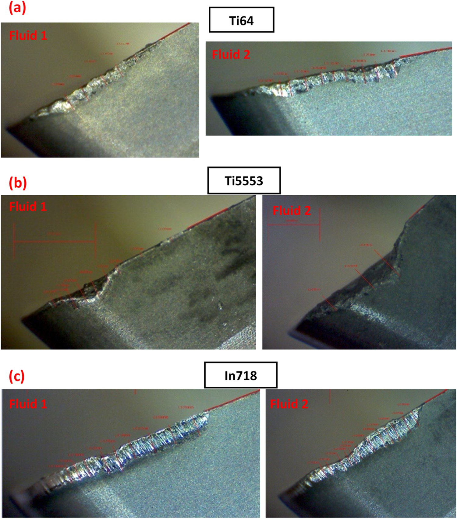
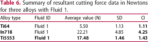
Figure 10 highlights that the better-performing fluid was Fluid 2 with higher tool life achieved when machining all alloy variants. This graph also highlights that Ti64 was the easiest alloy to machine with higher cutting speeds utilized during trials. Use of lower speeds was necessary for In718 indicating that it was the hardest material to cut. This would not be predicted based on material hardness alone (Table 4) but is supported by the cutting force data of Figure 12. Cutting forces were measured during the machining of all three alloys with Fluid 1 to further understand the difficulty of machining the alloy variants. Each block of coloured bars in the figure is the result of a repeat force test for each of the alloys with Fluid 1. Figure 12 highlights that Ti64 milled with distinctly lower forces, Ti5553 with an intermediate force level and In718 with the highest forces. The force levels observed when machining In718 and Ti5553 are similar. In this sense, Ti5553 has more in common with nickel-based In718 than with the other titanium-based alloy Ti64. As for the case of tool life, this pattern would not be predicted on the basis of standard material hardness testing.
Comparison of repeat resultant cutting force data for three alloys and Fluid 1. Each block of coloured bars in the figure is the result of a repeat force test for each of the alloys with Fluid 1.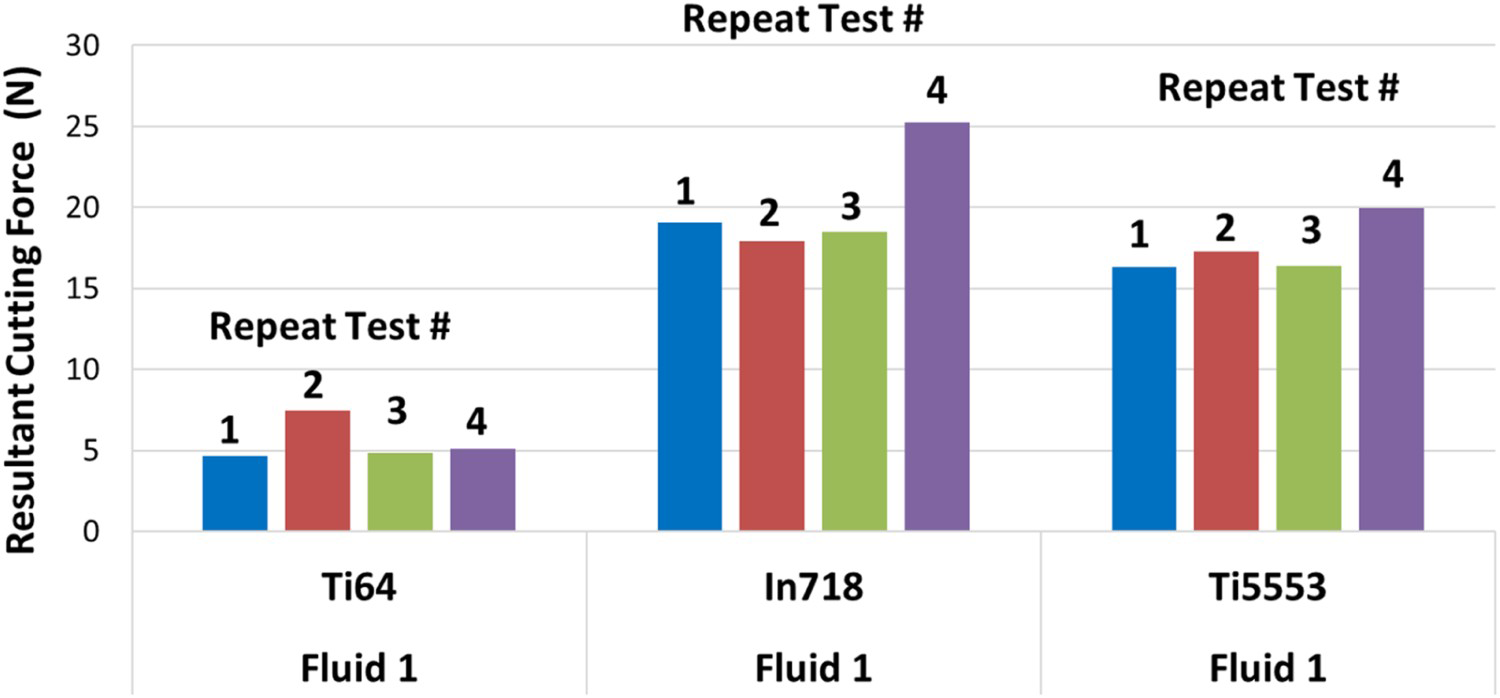
Summary of resultant cutting force data in Newtons for three alloys with Fluid 1.
This SPM process demonstrated itself to be a simple and inexpensive method of testing fluid performance in milling. Compared to the authors’ previous work [13], these trials used 4 repeat tool life tests rather than 12 so resource efficiency is higher. The use of single inserts improved repeatability and reduced testing variability compared to solid carbide tools. Solid carbide tools have multiple flutes with potentially varying tolerances for each cutting edge which would impact the variability of results [22]. The ratio of (SD/Average) for tool life results when milling Ti64 alloy with four-fluted solid carbide tools from previous work by the authors was 13%, compared to values of 1% and 9% for Ti64 milling with a single tooth from this study, indicating lower uncertainty in this study. De Chiffre and Belluco's [16] work includes summary data for repeat tool life testing used to evaluate MWF performance in drilling and turning. The SD shown was between 10% and 65% of the mean value, whereas referring to Table 5 and this project's milling method, the worst-case SD for tool life (Ti5553 with Fluid 1) was 11% of the mean value. This SPM methodology demonstrates a high repeatability and provides confidence in the sensitivity of the results produced which is necessary when the performance differentiation between two different fluids is below 20%.
Eight speeds were used to construct a tool life graph (Figure 3) for Fluid 1 for all three alloy variants, allowing surface speeds achieving 15- and 25-minute tool lives to be determined. Using this data, cutting speeds that would achieve 20-minute tool life for all material variants with Fluid 1 were interpolated. This tool life criterion of 20 minutes allowed tool failure to be achieved without consuming a large machining time and cost. Excessively high speeds and short testing periods (sometimes referred to as ‘accelerated testing’) would lead to stochastic tool wear and tool failure with low repeatability [12].
For Ti64 (Figure 4) and In718 (Figure 6) the error bars for the derived speed to achieve 20-minute tool life are all relatively small and provide confidence in the data and behaviours observed. For Ti5553 (Figure 8) overlaps in the error bars were highlighted and were expected due to the well-referenced machining behaviour of this alloy. Titanium materials have a low thermal conductivity which limits heat transfer and reduces the ability of MWFs to penetrate the cutting interface. This can cause a localization of high cutting temperatures at the tool tip during cutting. At these high temperatures, the near-beta Ti5553 material retains its high hardness which leads to high cutting forces as observed in Figure 12. This alloy can exhibit a high chemical affinity to the surface treatments applied to the cutting tools which exacerbate early tool failure [15]. The difficulty to machine this alloy plays a role in the stochastic behaviour observed in these trials with the different machining speeds and fluid variants [15,23–27]. Ti5553 is shown to be the harder to machine titanium alloy, and less material transfer onto the cutting edges was observed. The inserts used to machine In718 showed signs of scoring potentially from abrasive wear as well as relatively rapid wear rates, which are consistent with hard inclusions known to exist with In718 and are supported by the high cutting forces measured.
For all material variants (Figure 10) Fluid 2 increased the average tool life in all cases. With Fluid 2, there was a larger tool life variation with the titanium materials in comparison to In718, this may be due to a negative tribochemical interaction or chemical instability between the alloy and the fluid components [28]. This study highlighted the higher cutting forces and lower machinability of Ti5553 in comparison to Ti64, similar trends were observed by Arrazola et al. [14] who believed this was due to the higher hot hardness and the increased Mo equivalency of Ti5553.
It can be expensive to carry out individual tests to assess the effectiveness of previously untested MWFs. This study provides a cost-effective and simple fluid screening test that can be utilized by industrial stakeholders to select an optimum MWF to reduce cutting tool wear during machining processes [16,29].
The next stage of this testing methodology (future activity) would include cutting force analysis with both MWF variants and analysis of machined surface quality. This would provide additional information to support fluid behaviour and performance trends, mostly derived from tool wear measurements collected so far.
Conclusions
This study aimed to develop a laboratory focussed machining test which would allow the assessment and differentiation of metalworking fluid (MWF) performance during the milling of aerospace alloy variants. The study's key conclusions are:
Using a single cutting insert helped to increase trial repeatability whilst reducing the consumption of trial resources. This new methodology reduces the number of tool life tests per fluid/alloy combination, which in turn helped produce a more cost- and time-efficient machinability methodology. Standard deviation was utilized to analyse the tool life results and assess the repeatability of the tests for each fluid and alloy variant. Of the three alloys tested, Ti–5Al–5Mo–5V–3Cr (Ti5553) produced the least repeatable tool life testing results. Flank tool wear measurements combined with cutting force measurements can give an indication of cutting fluid performance in improving the durability of the cutting tool life. Ti5553 was deemed difficult to machine in terms of high tool wear rates compared to titanium alloy Ti–6Al–4V (Ti64). This was supported by the measurement of significantly higher cutting forces and Brinell bulk hardness values for Ti5553 compared to Ti64. Inconel 718 (In718) was the hardest of the three materials to machine in terms of tool wear in spite of having the lowest Brinell bulk hardness levels. Tool wear mechanisms observed included workpiece alloy adhesion when milling Ti64 and In718. Score marks down the tool flank were most prominent when milling In718. The MWF chemistry packages can impact cutting tool life behaviour. When comparing the performance difference between two distinct MWF types, there was an 11% improvement in average tool life with Ti64, 4% with In718 and 5% with Ti5553 when switching from the first test fluid to the second test fluid.
Footnotes
Acknowledgements
Gratitude is expressed for the technical assistance of colleagues Matthew Broderick and Matt Cawood.
Disclosure statement
No potential conflict of interest was reported by the author(s).