
Abstract
Strong protection capability of zeolite coating for AA6061 substrate from corrosion in NaCl, H2SO4 and NaOH solution has been demonstrated with reduction of corrosion current by five orders of magnitude. Film resistance was identified as the governing parameter in the formation of a barrier shielding the penetration of aggressive species. For the MFI zeolite film growth on the surface of the AA6061 substrate, while the in situ crystallisation (InC) protocol generated loosely packed film made of large zeolite crystal, the dry-gel conversion (DGC) protocol prepared dense film comprising of nanoparticles. Superior protection ability of DGC-grown film is attributed to the increased film resistance associated with a dense and impermeable zeolite layer. As such, the DGC-grown film requiring thinner film thickness around 5 μm showed better anti-corrosion function than the InC-grown film.
This paper is part of a supplementary issue from the 17th Asia-Pacific Corrosion Control Conference (APCCC-17).
Introduction
Anodic aluminium oxide, hexa- and trivalent chromium, Cr(VI) and Cr(III) coatings have been the mostly applied coatings for metal to provide adequate anti-corrosion property toward the attacks from destructively aggressive environmental components. Owing to the concerns on the carcinogenic Cr(VI) compounds, there is a need for a more environment-friendly alternative. Currently, only very few environmentally friendly Cr-free coatings have been reported having satisfactory anti-corrosion property. Some organic, inorganic and organo-inorganic hybrid coating, composite and surface modification using sol–gel, hydrothermal, coating processes have been proposed as possible substitutions to chromate. Metroke et al. and recently Wang and Bierwagen have reviewed the use of sol–gel coatings of ZrO2, SiO2, SiO2–TiO2, SiO2–A12O3, etc. as possible substitutions to chromate coating [1,2]. However, inorganic coatings are prone to crack and may not provide adequate corrosion protection. They may also require a high curing temperature not compatible with many metal alloys.
Zeolite is a cation exchangeable negatively charged silica–alumina oxide framework. Coating of zeolite film on the metal surface for corrosion protection has been done by the growth of a zeolite film from a synthesis gel, or by cross-linking of zeolite containing composite made from zeolite powder and sol–gel solution [3–7]. While the sol–gel route could be more versatile by requiring a shorter processing time, the directly grown film is more effective, particularly for severe corrosive environments. Several zeolite film growth methods, namely in situ crystallisation (InC), dry-gel conversion (DGC) and secondary growth, have been reported [3–5]. The property of a zeolite coating changes with the preparation procedure in a complicated and divergent way [8–10]. Very few mechanistic studies have investigated the governing parameters of zeolite film property for its corrosion protection property. The design principle on the understanding of governing parameters for optimising zeolite property by applying proper preparation protocol needs to be developed. The present paper studies the effect of zeolite growth protocol and the governing parameters of zeolite film property on corrosion protection property.
Experimental
Substrate pre-treatment procedure
AA6061-T6 aluminium alloy was cut into 2 × 2 × 0.1 cm pieces and used as the substrate. The polished metal piece was further immersed in 30% H2O2 for 45 min for oxidation of surface aluminium, or in 1N NaOH solution for 30 min for cleaning the surface, and then rinsed with distilled water.
DGC film (or steam-assisted crystallization of dry film)
The DGC preparation procedure for growing MFI film on the AA6061 substrate was reported [5]. A mixture of tetraethyl orthosilicate (TEOS): 0.25 tetrapropyl ammonium hydroxide: 20 H2O was stirred until it becomes a homogenous solution. A small quantity of Tween-20 (polyoxyethylene 20 sorbitan mono stearate, Tween-20/SiO2 = 0.01 w/w) was added to improve the wetting of the substrate. The final precursor sol remained stable for over 5 weeks at room temperature.
The above precursor sol was deposited on the substrate by dip coating (5-min immersion and 2.4 cm min−1 withdrawing rate). The coated substrate was placed on top of a stainless steel frame in a 125 mL polytetrafluoroethylene (PTFE) cup containing y mL of distilled water. The whole setup was enclosed inside an autoclave at 180°C for various durations. The film produced after x hours were denoted as DGC-Tx-wy.
InC method
Zeolite film was grown on the surface of Al alloy substrate from a solution in the composition of 1 SiO2:0.41 (TPA)2O:150.4 H2O at 180°C for 12 h. The film prepared from the H2O2-pre-treated substrate was denoted as InCO-T12 and the one pre-treated with NaOH was denoted as InCB-T12. Subject specimen for thermal stability test and removal of TPA template, the zeolite coating denoted with an ending code of –CA was prepared from the as-synthesised sample through calcination at 540°C (heating rate of 0.5°C min−1) for 20 h under a nitrogen gas stream containing 2-20% oxygen in either a continuous flow tubular reactor or a muffle.
Electrochemical property measurement
The room-temperature corrosion behaviours of the MFI zeolite-coated Al alloy in 0.5 M (3 wt-%) NaCl, 0.1 M H2SO4, 0.1 M NaOH and H2SO4–NaOH aqueous solution at various pH were investigated with a model CHI-627D electrochemical spectroscope (CH Instrument). A saturated calomel electrode (SCE) was used as the reference electrode, while a platinum wire served as the auxiliary electrode. The working electrode was either a bare substrate or one coated with zeolite film. Both were immersed 0.78 cm2 into the solution. The potentiodynamic polarisation spectrum was taken with d.c. polarisation scan, beginning at 2 V vs. SCE with a stabilisation time of 1 min, and continuously in the anodic direction at 5 mV s−1. Electrochemical a.c. impedance spectroscopic (EIS) measurements were performed at room temperature in a Faraday cage using a frequency response analyser and an electrochemical interface connected to a computer. The measuring frequency ranged from 105 Hz down to 10−2 Hz.
Results and discussion
Preparation of zeolite coatings on 6061 Al alloy substrate
Various zeolite films were grown with InC or DGC method on different pre-treated 6061 Al alloy substrates. The 6061 Al alloy substrate could be pre-treated with various protocols to facilitate the film growth. According to the previous study, the surface morphology of 6061 Al alloy substrate does not change after H2O2 pre-treatment leaving with polishing trails having a peak height of around 100 nm and valley in depth of around 50 nm being generated during sand paper polishing [11]. On the other hand, the surface of after NaOH pre-treatment becomes distributed with an irregular swamp in 10-25 μm diameter.
Under the InC conditions, the heterogeneous nucleation of zeolite occurred on the metal surface, while the homogeneous nucleation happened in the solution phase. The zeolite crystals showed strong adhesion on the aluminium plate [12]. Those generated from the homogeneous nucleation were only loosely attached and could be rinsed away during ultrasonic treatment without affecting the densely grown film. The morphology and thickness of MFI film are usually controlled by hydrothermal conditions (temperature and time) and the reactant compositions. On the other hand, under DGC method, the precursor solution is first pre-deposited on the 6061 Al alloy substrate to form a dry gel; and then the dry precursor is steam-assisted ‘in-situ’ crystallisation into the zeolite film. Therefore, the film thickness of MFI film could be controlled directly by the amount of precursors coated before the steam-assisted conversion process.
By the characterisation of X-ray diffraction patterns, all films showed the typical pattern of the MFI zeolite, suggesting that they were made of fully grown zeolite MFI. As shown in Figure 1, the X-ray diffraction pattern of zeolite MFI became stronger with extending DGC time; and the DGC-grown film exhibited complete zeolite MFI crystallinity at DGC time of 12 h. As a result of weakening diffraction by decreasing grain size in accordance with Scherrer equation, zeolite coating prepared with InC method exhibited much higher XRD intensity than those prepared with DGC method [13].
XRD patterns of various DGC-grown MFI zeolite films coated on AA6061 plates.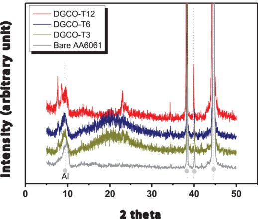
According to the SEM images (Figure 2), the particle morphology and thickness of MFI zeolite films changed with the preparation protocol. When using the InC process, the film InCO-T12 and the film InCB-T12, -T20 and -T40 all were in loosely packed multi-layer, consisting of randomly stacked crystals with hexagonal prism shape. Notice that upon increasing hydrothermal time, the MFI film became denser packing with more crystal inter-growth and thicker with increasing thickness from 15 to 60 μm in the InCB-T12 and InCB-T40 film, respectively.
SEM images at different magnification scales of various as-synthesised MFI films (a) InCB-T12 (×10,000); (b) InCB-T40; (c) DGCB-T12-w1 (×1,000) and (c−1) (×30,000); (d) DGCO-T12-w1 (×10,000) (inset: cross section view).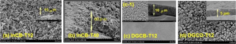
On the other hand, DGC-grown films were in dense layers made of closely packed spherical agglomerates of around 250-500 nm particles. The production of round-shape nanocrystal was expected, as the nucleation occurred under a rather high silica concentration [14]. The difference in packing density between InC and DGC processes is attributed to the zeolite crystal morphology. The nano-sized spherical crystals prepared from DGC method could pack closer and denser than the micro-sized prism shape crystal prepared from InC process. Notice that the thickness of the DGC-grown film was always thinner than that prepared by the InC process. For example, the thickness of DGCO-T12-w 0.01, 0.1 and 0.5 was 2, 4 and 4.5 μm, respectively.
Protection of zeolite-coated 6061 Al alloy substrate against salt corrosion
Corrosion parameters derived from the polarisation curves of the different coated method in 3 wt-% NaCl solution.
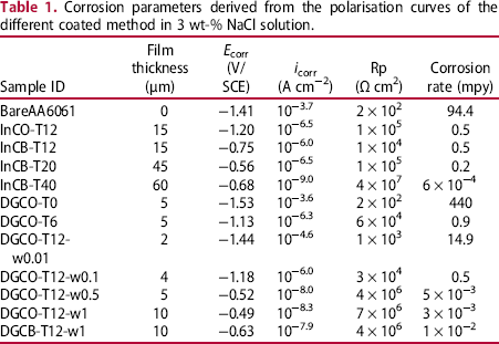
For the DGC-grown films, the i corr of the listed MFI films was in the range of 10−5–10− 8 A cm−2. Therefore, DGC-grown MFI films could reduce the i corr of the AA6061 substrate by four orders of magnitude. Note that the DGC-grown films were much thinner than the InC-grown ones. The crystallinity effect on corrosion resistance was tested in Figure 3. The i corr of DRCO-T0 with a film thickness of 5 μm (AA6061 coated with zeolite precursor without DGC treatment) was exactly the same with that of bare AA6061. With extending DRC treatment, the i corr value decreased from DRCO-T0 to and T12. As a result of DGC treatment at 12 h, the DGCO-T12-w0.5 film exhibited a very low i corr value of 10−8.0 A cm−2. Therefore, it is concluded that crystallinity strengthened anti-corrosion resistance.
Electrochemical polarisation spectroscopy of AA6061 plate coating with DGC-grown MFI zeolite film. The measurement was done while immersing in 3 wt-% NaCl solution.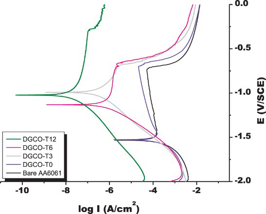
Figure 4 summarises the corrosion rates of various silica-coated AA6061. The corrosion current ranked in the order of bare AA6061, DGCO-T0, silica nanoparticle, InCO-T12, DRCO-T12. Similarly, as shown in Table 2, the DGCB-T12 sample with a film thickness of 10 μm exhibited a much lower i corr and stronger protection than InCB-T12. Therefore, the DGC-grown film was more effective for protection of AA6061 from corrosion than the InC-grown film. The superior protection capability of the DGC-grown film is attributed to high crystal-packing density resulted from nanoparticle morphology (Figure 1). Presumably, MFI film-packing density plays a key role in the protection capability of MFI film. Whereas increasing film thickness could increase film resistance providing stronger protection from the attack of aggressive species, intensified film-packing density through crystal morphology control could reduce film voidage and strengthen the protection capability of film.
Corrosion rates of various silica-coated AA6061 in 3 wt-% NaCl solution. Electrochemical parameters of the experimental EIS curves of bare and MFI zeolite-coated alloy AA6061 while immersing in 3 wt-% NaCl solution. aUnit: R in bZeolite film calcined at 540°C in air for 20 h.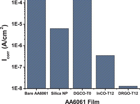
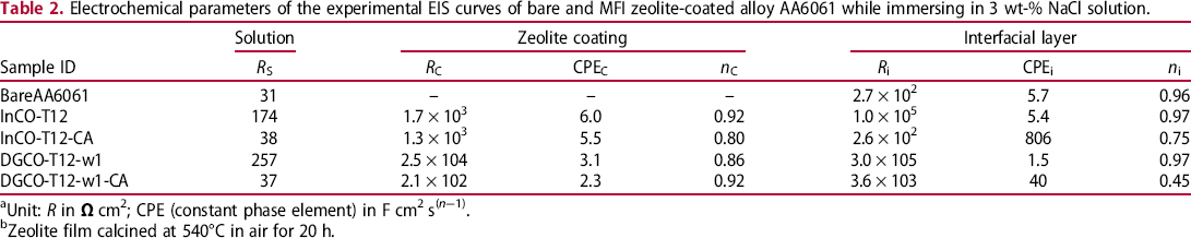
Electrochemical impedance spectroscopy (EIS) was studied. The frequency domain corresponding to the outmost layer to metal substrate decreases accordingly. In reference to the literature, the relaxation phenomena in the high-frequency domain in the Bode diagram could be attributed to the outmost protection layer arisen from zeolite coating [15–17]. The one in the low-frequency region is ascribed to the existence of an interfacial layer between the zeolite film and the aluminium alloy substrate. The experimental EIS data were fitted with different electric circuits comprising with resistive terms R S, R C and R i accounting for the resistances of electrolyte, zeolite film and zeolite–alloy interfacial layer, respectively. Therefore, the contribution of individual coating layer could be elucidated from EIS data.
As shown in Table 2, in comparing to the R i of the outmost interfacial layer in the bare Al alloy plates, the zeolite-coated A6061 possessed much higher R C for the outmost zeolite layer and R i for the interfacial layer. R C changes with the thickness, density and structure of the zeolite film. The high R C value represents strong film resistance and protection against the penetration of Cl− ion through the solid phase. Accordingly, the Cl− ion concentration reaching the interfacial layer reduces; and R i would increase. As a result, increasing R C value accompanying with the down-field shifting of the high-frequency domain would induce high interfacial layer resistance R i. In referring to the InC-grown film, the DGC film with higher film-packing density had higher R C providing with stronger R i. As expected, stronger corrosion protection of DGC-grown film than the InC-grown film was observed. Accordingly, film resistance R c is one of the major governing element for corrosion protection. Film resistance could be increased with increasing thickness and density as well as film structural integrity. Whereas increasing film thickness could increase film resistance, intensified film-packing density could reduce film voidage and strengthen the protection capability of film.
TPA is always used to assist the formation of MFI structure by which TPA was occluded at the intersection of MFI zeolite channels. It is interesting to study the TPA role in the corrosion protection of zeolite film. The as-synthesised DGCO-T12-w1 and InCO-T12 films were thermally treated at 540°C under 2% oxygen containing nitrogen. As a result, the impedance of InCO-T12-CA and DGCO-T12-w1-CA descended following about the same behaviour with the bare AA6061 but providing a higher impedance.
Subjected to air calcination, MFI film became a porous structure having micropores after TPA removal and macropores after crack formation. The TPA-free zeolite film allowed the electrolyte solution to penetrate into the interfacial layer through the microporous channels and macropores. Among various factors, the film resistance R C depends on the voidage and film thickness. Consequently, the concentration of corrosion species in the interfacial layer of the calcined MFI zeolite film should be much higher than the case of the as-synthesised ones, leading to a much lower interfacial layer resistance R i. Notice that R C of the calcined film all decreased accompanying with a sharp reduction in R i (Table 2). In contrast to the characteristics of as-synthesised films, the calcined DRC-grown film with thinner thickness exhibited significantly lower R C than the calcined InC-grown one. Possibly due to low macro-porosity, Cl− ion penetrated slower in the former providing reduced Cl− ion concentration in the interfacial layer than that in the latter. Accordingly, the former still had higher R i than the latter. The EIS data indicate the indispensable role of TPA by blockade of zeolite micropore channels for exerting maximum protection of MFI film.
Protection of zeolite-coated 6061 Al alloy substrate against acid and base corrosion
The anti-corrosion ability of DRC-grown zeolite MFI film DGCO-T12 was examined in electrochemical measurement while immersing in 0.1 M H2SO4–0.1 M NaOH mixture at various pH values. At pH = 1, the bare AA6061 and DGCO-T12 film exhibited good acid resistance showing low i corr of 10−5.8 and 10−7.2 A cm−2, respectively, at corrosion potential around −0.4 V/SCE. As shown in Figure 5, the DGCO-T12 remained stable and anti-corrosion effective in a wide pH range below 12. At pH of 13 in 0.1 M NaOH solution, while AA6061 suffered serious corrosion showing high i corr (10−3.9 A cm−2), the DGCO-T12 film exhibited low i corr of 10−6.1 A cm−2. In comparison, the DGCO-T0 film can be stable only at pH lower than 9 with a medium corrosion protection capability. Therefore, zeolite film is applicable as a whole pH spectrum. It showed robust protection capability by 100-fold stronger than silica in a strong basic environment.
The corrosion rate of AA6061 coating with DGC-grown MFI zeolite film. Electrochemical polarisation spectroscopy was taken in H2SO4–NaOH solution.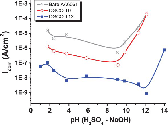
Conclusions
Strong protection capability of zeolite coating for the AA6061 substrate from the corrosion by aggressive species NaCl, H2SO4 and NaOH has been demonstrated. As revealed in potentiodynamic polarisation spectroscopy, MFI zeolite film-coated AA6061 is corrosion resistant to the entire pH range. Meanwhile, the potentiodynamic polarisation spectroscopy and by EIS both indicate the strong protection capability of MFI zeolite film for Al alloy in NaCl solution. In reference to the bare substrate in NaCl solutions, MFI film exhibited decreasing corrosion current by five orders of magnitude. The protection ability of zeolite film is attributed to the increased film resistance associated with a dense and impermeable zeolite layer. By using proper crystal morphology, the DGC-grown film consisting of nanoparticles exhibited higher film-packing density than the InC-grown film.
The micropores and channels blocked by the structure-directing agent (SDA) TPA during zeolite crystallisation formed a barrier shielding the penetration of aggressive species. The anti-corrosion function of this zeolite layer deteriorated after the removal of the SDA by combustion. Consequently, the TPA molecule is an indispensable element of MFI anti-corrosion film.
Footnotes
Acknowledgements
The authors are grateful to Professor Anthony S.T. Chiang for fruitful discussions.
Disclosure statement
No potential conflict of interest was reported by the authors.