
Abstract
Corrosion-resistant alloys (CRAs) are employed in severe oil and gas production environments that operate at high pressures and temperatures and contain chlorides, CO2, and H2S. They exhibit high resistance to uniform corrosion in these environments due to their passivity. However, they can suffer from different forms of environmentally assisted cracking (EAC), depending on the environmental and metallurgical conditions. This paper reviews the recent literature of EAC in CRAs and presents an overall framework for evaluating the SCC based on electrochemical modelling of corrosion and repassivation potentials for localised corrosion. The modelling is supported by experimental data on crack growth as a function of environmental variables, alloy content, and potential.
This paper is part of a supplementary issue from the 17th Asia-Pacific Corrosion Control Conference (APCCC-17).
Keywords
Introduction
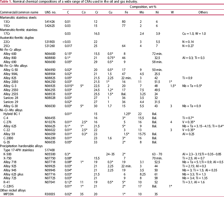
Nominal chemical compositions of a wide range of CRAs used in the oil and gas industry.
CRAs can suffer a variety of EAC phenomena. At pH below the depassivation pH (pHd), CRAs can undergo active, uniform corrosion. In the absence of other cathodic reactions, active corrosion results in the generation of hydrogen as the cathodic reaction, leading to hydrogen embrittlement. This is the case for sulphide stress cracking (SSC), where the presence of reduced sulphur species promotes the entry of atomic hydrogen into the metal [10]. However, hydrogen entry into the metal can also result from cathodic polarisation due to galvanic coupling with more active metals or due to electrical coupling of CRAs to cathodically protected steel. This is defined as hydrogen stress cracking (HSC) or galvanically induced hydrogen stress cracking (GIHSC) [10]. At pH values more positive than the pHd, and potentials more positive than the proton reduction potentials, anodic stress corrosion cracking may occur due to various local dissolution mechanisms. At pH values close to the pHd, active to passive transition current density may be high [15]. Under these conditions, SCC may occur because of the effect of plastic deformation on the active–passive current density. At pH values significantly above the pHd, such a large active–passive transition current may not exist [15] and SCC may be driven by the tendency of the alloy to suffer localised corrosion (pitting or crevice corrosion).
ISO 15156 provides a number of guidelines for the selection of CRAs for sour service [11]. The localised corrosion resistance of the CRAs is often ranked by the pitting resistance equivalent number (PREN), which is given by (wt-% Cr+ 3.3 wt-% (Mo + 0.5 W) + 16 wt-% N) [11]. The correlation of PREN to localised corrosion susceptibility is dependent on the chloride concentration and the corrosion potential, but is used as way to rank the alloys. The limits of SCC resistance are given in terms of chloride concentration, temperature, pH, and H2S partial pressure [11]. The resistance of CRAs for SSC and HSC are given more qualitatively in ISO 15156. These limits were established through a combination of laboratory studies and field experience.
Previous reviews, notably those by Rhodes [12], Turnbull and Griffiths [13], and Ueda [14], have discussed the performance of CRA in sour environments extensively. The objective of the present review is to fill in some of the details, extend previous information, and provide a framework for understanding the results.
Test techniques
A brief overview of the types of approaches and their strengths and limitations is provided to form the basis for subsequent discussions. The reader is referred to the standards and other literature cited in the subsequent sections for details of the test techniques.
Localised corrosion testing
Long-term immersion test at open-circuit potentials in the relevant environments is a common method to measure the corrosion rates and characterise the extent of localised corrosion (depth, area, etc.). Although, these tests yield information on the corrosion behaviour under natural exposure conditions, the main uncertainty of such tests is the sufficiency of time for the incubation of localised corrosion. This problem is especially acute for highly alloyed CRAs where the open-circuit potential can evolve over several months as passive films improve [16]. Therefore, applied potential tests are performed under suitable environmental conditions with or without intentional crevices. In such tests, the problem can be split into two parts – measurement of critical potential and corrosion potential. For the former case, cyclic potentiodynamic polarisation (CPP) scans [17] are often performed at a relatively slow scan rate of 0.167 mV s−1, starting typically from open-circuit potential, and cycling back to the potential at which the backward potential scan intersects the forward scan. A typical polarisation in a H2S-containing solution is shown in Figure 1 [18], along with a schematic illustration of critical points in the curve. In the region 1-2, above about −300 mV vs. saturated calomel electrode (SCE) maintained at room temperature (SCERT), H2S oxidation occurs with a nearly Tafel behaviour masking the anodic dissolution currents. This is a function of H2S concentration, with the deflection point occurring at lower potentials for higher H2S concentration. In the region 2-3, localised corrosion causes a rapid increase in current, in contrast to H2S oxidation that could become diffusion limited. On the return scan, the point of intersection with the forward scan (Point # 5) is typically regarded as the repassivation potential (E rp). However, a deflection in current is also observed as illustrated by Point # 4. This deflection could be due to the cessation of crevice corrosion or reduction of other oxidised species in solution. If the deflection Point # 4 is within 10 times the passive current density, this is taken as the E rp. It is further confirmed by conducting potentiostatic holding test below this inflection point. In some cases, inflection point # 4 was not distinctively revealed, E rp is arbitrarily defined at intersection point #6 of reverse scan with vertical line of 10 times of passive current density (dotted vertical line).
The effect of H2S on CPP curve for a martensitic stainless steel. The right-hand side curve illustrates the critical points in the polarisation curves, including inflection points [18].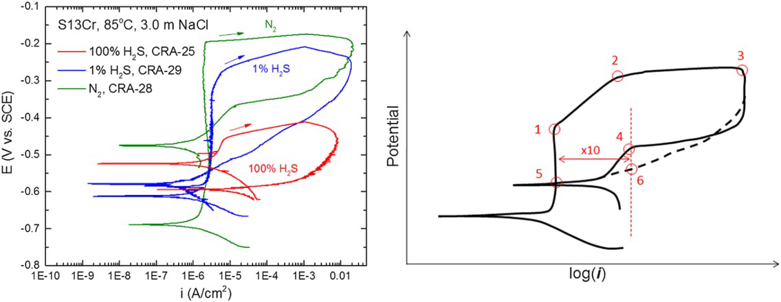
An alternative to the CPP test is the ASTM G192 test (also known as the Tsujikawa–Hisamatsu Electrochemical or the THE test) [19]. In this test, the potential is raised to a value at which pitting or crevice corrosion initiates, the current is then held constant until a pre-defined charge density is attained, then the potential is decreased at a pre-determined stepwise way until the measured current shows a monotonic decrease, indicating repassivation. The main advantages of this method are that the localised corrosion is controlled by galvanostatic polarisation for fixed charged density and the repassivation potential is determined by monitoring current decrease at each potentiostatic step. Faster test variations of the THE method, with either greater potential step changes or reduced time intervals between potential changes, were also performed to determine a conservative E rp, e.g. potentiodynamic–galvanostatic–potentiodynamic test [20,21], and potentiodynamic – potentiostatic – potentiodynamic test [22,23]. Because of the interference from H2S oxidation, some authors have used electrochemical noise measurements to determine a critical pitting/crevice temperature [24]. The test yields critical localised corrosion temperature, but it lacks predictive power. However, it can be used to verify localised corrosion models.
Environmentally assisted cracking tests
For EAC to occur, the potential must attain a critical value, while the plastic strain rate is maintained above a certain value that is dependent on the alloy–environment combination [18], as illustrated in Figure 2(a). Even if macroscopic plasticity is not attained, there is evidence that microplasticity exists for promoting EAC [25].
Electrochemical and mechanical conditions needed for EAC to occur. Schematic polarisation curve indicating possible critical potential regions for EAC [18].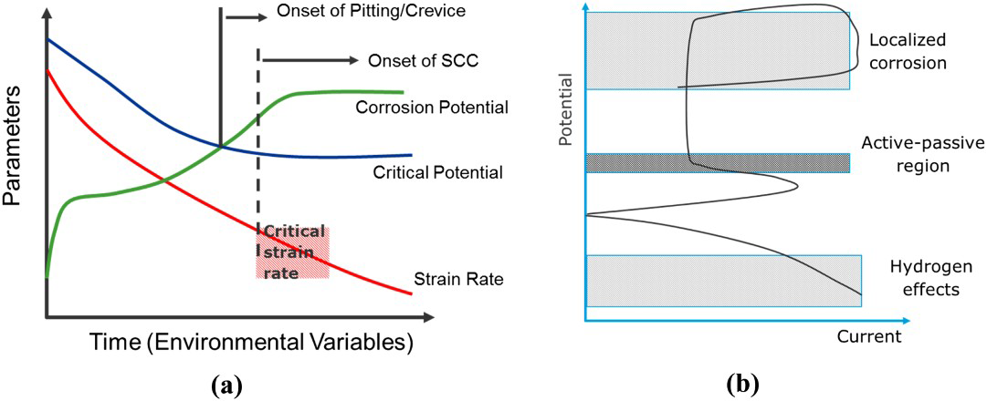
The critical potential may be the repassivation potential for localised corrosion or the active–passive transition potential for SCC or a cathodic potential for HE. SCC has been shown to occur at the active–passive transition for carbon steels and other alloys [26,27], but this has seldom been demonstrated for CRAs in oil and gas environments. SCC usually initiates from localised corrosion, which occurs above the repassivation potential, marked in Figure 2(b) as the cross-over point of the polarisation curve. It should be noted here that from a mechanistic perspective, HE may contribute to SCC in pits where an acidic electrolyte and low potential may co-exist, but the overall EAC mode is still termed SCC. HSC or GIHSC occurs at cathodic potentials (Figure 2(b)). However, attaining the critical potential region is a necessary, but not a sufficient condition, as strain rate at the crack tip must also be maintained above a certain value. Thus, higher temperatures may contribute to increased SCC susceptibility through reduced critical potential and higher strain rates. The metallurgical structure may also provide important boundary conditions required for critical strain rates. For example, if a microstructure permits dislocation pile-up at interfaces, the critical strain rate may be lower.
The most utilised test methods for cracking susceptibility are the constant deflection (e.g. C-ring, U-bend, and 4-point bend tests) and the constant load (e.g. proof ring test) [12–14,28]. The advantage is the simplicity of the tests, the ability to expose many samples to a given environment simultaneously, and the simulation of appropriate product forms (e.g. tubulars). The main disadvantage of the test is that the strain rates decrease with time to negligible levels due to work hardening and this drop in the strain rate can reduce cracking susceptibility. A notch can be added to these tests either to increase the severity of loading or to localise cracking to specific features such as welds and heat-affected zones. A minimum exposure duration of 720 hours is recommended. However, in the case of high-alloyed CRAs considerably longer test durations may be required, in some cases exceeding 10 months. Regardless of the exposure period, one is left to wonder whether longer exposure would have resulted in cracking.
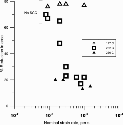
An alternative to the constant load/deflection test is the slow-strain rate test (SSRT), which has been reviewed comprehensively by Henthorne [29]. The principle behind SSRT is the maintenance of plastic deformation that is required to cause stress corrosion cracking. The typical initial strain rate used is 10−6 s−1. Although SSRT is generally regarded as a more severe test than the constant deflection tests, in many stainless steels that has not been found to be the case. In dilute chloride environments, SCC has been observed in constant deflection tests, but not in SSRT [30,31]. This may be related to the effect of strain rate and test duration (Figure 3) [31,18]. At the higher strain rates, the localised corrosion did not occur prior to the overload failure of the specimen [18]. Correspondingly, no SCC was observed. At the slower strain rate, localised corrosion occurred prior to failure and significant SCC was found. Alternatives to SSRT include the cyclic SSRT, wherein a ripple load (e.g. from 90 to 100% of measured load at any strain) is superimposed on the static load during straining at a relatively low frequency of 0.001 Hz, or interrupted SSRT, where the loading is stopped after attaining plastic deformation and the specimen allowed to creep over a longer period of time [18]. The optimum strain rate for SCC could depend on the alloy, environment, and temperature combinations, as shown in Figure 4 for a Ni-base alloy [32].
Effect of strain rate on cracking susceptibility of a martensitic stainless steel. Also shown is the anodic current from polarisation of the specimens [18]. Effect of strain rate on SCC susceptibility of alloy UNS N06985 in 25 wt-% NaCl +0.5 wt% acetic acid +0.7 MPa (100 psi) H2S (at RT). Redrawn from [32].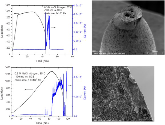
Pre-cracked specimens have also been widely used. The double cantilever beam test in which a pre-cracked specimen is wedge loaded and exposed in the environment for different periods of time is used as a standard test [33]. The recommended exposure duration is 720 hours, after which the specimen is cleaned and placed in a tensile machine to measure the load–displacement curve. The main limitations of this technique are the arbitrary duration of exposure, the lack of continuous crack growth data, and the potential for the crack to deviate significantly from its original plane.
In situ crack growth rate (CGR) measurements in environments using potential drop techniques were pioneered by Andresen [34] and provide the means to study the effect of changes in environmental conditions on EAC in a controlled manner on a single specimen. In this approach, a compact tension (CT) specimen is used with a width and length of either 25.4 or 50.8 mm (1 or 2 inches) and a thickness of 6.35 mm (0.25 inches). The notches are machined with electro discharge machining and pre-cracked to an initial crack length/specimen length (a/W) of 0.3 or 0.35 at a final stress intensity factor range (ΔK) of 16.35 MPa.m0.5 (15 ksi.in0.5), such that the plastic zone size from fatigue pre-cracking does not unduly influence subsequent SCC. The crack growth is measured either using a direct potential drop or a reversed pulse potential drop technique [35]. During the environmental exposure, the crack is ‘encouraged’ to grow by providing sufficient cyclic loading slowly tapering off the cyclic component to a near-static loading [34]. For example, cyclic loading is started with an R-ratio (ratio of minimum stress intensity factor over maximum stress intensity factor) of 0.1 and a frequency of 1 Hz, then the frequency is slowly reduced to 1 mHz and the R-ratio slowly increased towards 0.8-1. Once a crack is growing at a near-constant stress intensity factor, changes to the environmental conditions or applied potential can be made to evaluate changes in CGR, as illustrated in Figure 5 [18].
In situ crack growth measurements using a single CT specimen and varying the environmental conditions [18].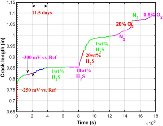
A decrease in load (load shedding) is necessary as the crack grows to maintain constant maximum stress intensity factor. In these tests, it is necessary to go back to stable crack growth conditions prior to every environmental change to ensure that changes detected are reproducible. Furthermore, maintenance of good temperature control and noise shielding is necessary to correlate changes in potential drop to crack growth accurately. Finally, at the end of the test, the sample should be opened to examine the fracture surfaces under a scanning electron microscope to verify crack growth and compare the extent of crack growth with potential drop measurements. Side grooves may be necessary for some cases to prevent crack plane deviation [33].
The CGR measurements described above provide an excellent approach to determining EAC sensitivity to environmental and metallurgical parameters. However, they are time consuming, as measurements can take from several weeks to more than a year depending on CGRs. Another approach is to continuously strain the pre-cracked CT specimens (also called rising displacement test) to failure at a slow rate (e.g. a stress intensity factor increase rate of 5 × 10⁻⁴ MPa.m0.5.s−1), while measuring crack growth using the potential drop technique [36]. These measurements yield fracture energy vs. crack growth curves, which are then compared between inert and test environments. Depending on the specimen geometry and fracture toughness properties, the resulting measurements may also be used in design criteria. The advantage of this test method is that it is less time consuming than the CGR method described previously, but the disadvantage is that it requires separate specimens for measurements and, therefore, not as elegant as measuring changes in CGR due to environmental changes on a single specimen. Combinations of rising displacement test with constant displacement or constant K can also be performed [37] since CGR is dependent on the crack tip strain rate as well as the loading method (e.g. rising K vs. decreasing K).
Test solution preparation
Generally, bottom hole environments have extremely low-oxygen fugacity. Because oxygen can increase the corrosion potential as well as chemically interact with H2S to produce elemental sulphur (S0), it must be rigorously excluded in the test solutions and the dissolved oxygen must be measured using sensitive techniques. Typically, the test cells are loaded with the specimen, closed, purged with nitrogen, the test solutions are deaerated in a separate vessel with nitrogen, and then the solution is pushed into the test cell using the inert gas. The use of polymeric tubing leading to and away from the test cells must be minimised as these can be permeable to air. Exit traps also ensure that oxygen does not enter the test cell. In tests conducted with S0, The manner of introducing elemental sulphur may affect the test results [12], although this issue has not been sufficiently resolved. The consensus is that attaching sulphur to the sample surface either through a crucible affixed to the specimen or taping sulphur powder is more aggressive than introducing sulphur in solution.
Effect of metallurgical variables on SCC and HE
Metallurgical factors influence the performance of CRAs in oil and gas production systems in essentially four ways: (i) plastic deformation behaviour of the matrix phase, (ii) effect of precipitation/second phase on plastic deformation behaviour, (iii) electrochemical response of the matrix phase, and (iv) effect of second phase precipitation on electrochemical behaviour.
Effect of alloying elements on plastic deformation of the solid solution alloys
Alloying elements have multiple effects on plasticity of solid solution alloys, including the increase in yield strength and the increase in slip planarity that leads to an increase in work hardening rate. Higher strength alloys do not automatically have a lower resistance to EAC. It is now well recognised that planar slip generally promotes SCC and HE [38–41], whereas it retards low-cycle fatigue crack growth [42–45]. The mechanisms behind the effect of planar slip on SCC/HE vs. fatigue appear to be different. In the case of fatigue, the formation of persistent slip bands, which are the origins of fatigue crack, seems to be retarded by a decrease in stacking fault energy (SFE) and increase in planar slip. In the case of SCC, it has been argued that planar slip leads to greater localisation of dissolution, modification of passive film properties, or increase of local stresses at grain boundaries. In the case of HE, the relationship between planar slip as characterised by lower SFE and hydrogen embrittlement appears to be more complex [46]. It is interesting that the effect of planar slip on SCC/HE and fatigue is opposite to each other and the confluence of these two processes in low-frequency cyclic loading may lead to a peak in crack growth as a function of increasing cycling frequency and perhaps amplitude of stress/strain.
In solid solution alloys, planar slip occurs because of low SFE, although recent studies have indicated a greater role for solute interactions as well as short-range ordering [47–50]. Many different empirical correlations have been developed for estimating the SFE as a function of alloy composition for stainless steels [46,51–55]. Theoretical modelling of SFE has been attempted using atomic level mechanisms [46]. The general view, reinforced by first principles modelling, is that for Fe–Ni–Cr alloys, Cr decreases the SFE while Ni increases SFE [55,56]. Although modern atomistic modelling has given us considerable insights into the estimation of SFE with alloying elements, a simplified procedure is needed to estimate the trends in SFE for complex, commercial alloys. We reach out to an old approach proposed by Brewer [57] based on d-sp orbital hybridisation. Although this approach has been criticised [58], it provides reasonable agreement of SFE trends with alloying elements, especially considering the errors inherent in SFE measurements. Essentially, the Engel-Brewer (E-B) approach [59] suggests that the electron/atom (e/a) ratio attains certain critical values for phase transitions – specifically elements with an e/a ratio of 1 typically exhibit a body-centred cubic crystal structure, elements with an e/a ratio of 2 exhibit hexagonal close packed (HCP) structure, and elements with an e/a ratio of 3 exhibit a face-centred cubic (FCC) structure. Because the intrinsic stacking fault in a FCC lattice can be regarded as a region of HCP structure, the SFE has been modelled in terms of FCC to HCP phase transformation [60]. The E-B rule was applied to predicting the SFE of Ni–Fe–Cr–Mo alloys [61] (Figure 6).
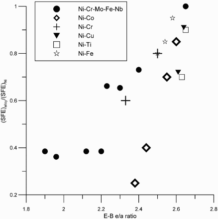
Ni tends to increase the E-B e/a ratio and hence SFE, whereas Cr and Mo tend to decrease this ratio and hence the SFE. The lower SFE of Ni–Cr–Mo alloys would generally mean higher planar slip and greater susceptibility to EAC if environmental conditions are appropriate [38–40]. Lee [46] arrived at a somewhat different conclusion for hydrogen embrittlement. Although his correlation of SFE to alloying elements is somewhat similar to that proposed above, he showed that the minimum in SFE does not correspond to a maximum in HE. He argued that the contribution of electrons from the hydrogen atom to the empty d-orbitals of the host transition metal near the Fermi energy should be considered in the effect of hydrogen on bond decohesion. His arguments rest of his correlation of hydrogen embrittlement susceptibility as a function of alloy content in binary alloys, such as Ni–Co alloys.
Effect of coherent phases on plastic deformation and EAC
The presence of short- and long-range ordering as well as coherent precipitates can also serve to enhance planar deformation and embrittlement. The role of short- and long-range ordering on hydrogen embrittlement has been demonstrated previously for Ni–Cr–Mo alloys [62,63]. As shown in Figure 7, aging at 500°C for a short time increases crack velocity and decreases time to failure of smooth samples, but continued aging for long times increases CGRs significantly. These changes can be due to a combination of ordering and grain boundary segregation of phosphorus [64–69]. It must be noted that the rapid kinetics of the aging process is due to the high degree of cold work that introduces a high concentration of defects. For annealed alloy, the ordering reactions are much slower [62]. A parallel study on a Ni–Fe–Cr–Mo alloy containing 20 wt-% Fe showed that the increase in CGR was much less marked due to aging [63]. Although short-range ordering was present in this alloy, long-range ordering did not occur. Since grain boundary segregation of P was likely to occur in both alloys, the difference in embrittlement susceptibility can be attributed to long-range ordering.
The effect of low-temperature aging on the hardness and hydrogen embrittlement susceptibility of a 59% cold worked Ni-base alloy (UNS N10276) [62].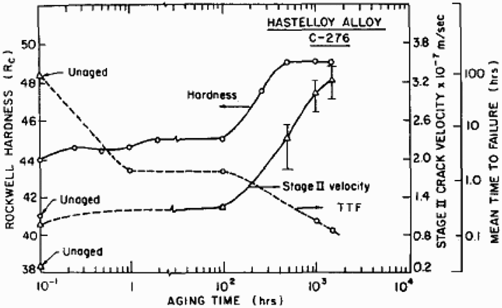
Lehman and Kosel [68] and Abd-Elhady and Sargent [69] showed that for model Ni2Cr intermetallic alloys containing different concentrations of P, the ordering reactions were accelerated by the presence of higher P. The ordering reactions have been shown to occur in other Ni–Cr–Mo alloys [70,71] and they occur very slowly in annealed alloys at temperatures below 500°C [72,73]. Some Ni–Cr–Mo alloys are aged at close to 700°C to form ordered Ni2Cr type phase in order to strengthen the alloy through heat treatment [74,75]. The effect of ordering reactions on high temperature SCC have not been studied as systematically, although the effect may be less significant than for HE [76,77].
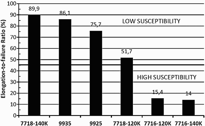
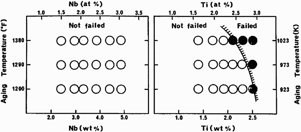
Although, ordering reactions are, by and large, unwanted reactions in CRAs, coherent precipitates, such as γ′ (Ni3Ti/Al type) and γ″ (Ni3Nb type), are intentionally obtained through heat treatments to increase strength without cold working [78]. The precipitation-hardened (PH) alloys are used in thick sections (e.g. tubing hangers) and in complex-shaped parts where strengthening by cold work is not possible. Generally, the γ′ alloys (e.g. X-750, R-41, K-500, 925) are more susceptible to EAC than the γ″ alloys (e.g. alloy 718, 725) [79]. Since alloying elements, such as Cr and Mo, also influence the localised corrosion behaviour under anodic conditions, it is instructive to examine the HE of these alloys to discern the effect of coherent precipitates. The lattice mismatch appears to cause greater loss in ductility (Figure 8), therefore γ′ alloys would be expected to exhibit greater HE [39]. However, the HE susceptibility is not only determined by lattice mismatch, but other factors, such as the matrix SFE and non-coherent precipitation. This is seen in a recent result [81] on the HE of a number of CRAs due to cathodic charging, where the γ″ alloy (718) showed the least embrittlement, but was followed by a γ′ alloy (935) and the most embrittled alloy was a mixture of γ′ and γ″ (716) (Figure 9). The SFE of alloy 716 (higher Mo and Nb) is likely to be lower than that of 718 and 935. These findings are consistent with those of Igarashi et al. [72] (Figure 10).
Effect of lattice mismatch between γ′ and the matrix on gaseous hydrogen embrittlement of Ni-base alloys [39]. HE susceptibility of a number of commercial PH alloys [79]. The difference between a γ′ (right) and γ″ (left) alloy on SCC in CO2+H2S environment [80].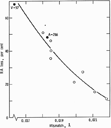
The effects of coherent precipitation on hydrogen embrittlement of alloys K-500 and X-750 have been studied in oil and gas production processes [81,82]. While these cracking occurrences have been at ambient temperatures, hydrogen embrittlement of alloy K-500 and other precipitation-hardenable alloys, such as alloy 925, has been shown to occur at temperatures up to 125°C (257°F) in MgCl2 brines under cathodic polarisation [83]. Another example of failure in oil and gas production is cracking of tubing hangers made of alloy X-750, a γ′ precipitation-hardened alloy, which was shown to be related to hydrogen embrittlement in combination with hardness above 35 in Rockwell C-scale (HRC) [84]. Hydrogen embrittlement of alloy 718, a γ″-type precipitation-hardenable alloy has occurred in high-pressure hydrogen gas when the alloy was double-aged to produce hardness above 40 HRC [27,84]. Hydrogen embrittlement of alloy 718 under cathodic charging conditions has been observed by several authors [85–88]. Hydrogen embrittlement in H2S-containing solutions has not generally been observed in 718, with the exception of a result from slow-strain rate testing [87]. In contrast to SCC/HE, precipitation of γ and γ′ in alloy 718 upon aging decreased the fatigue CGR (R ratio of 0.1 and frequency of 1 Hz) in NaCl solutions [89].
The transformation of the ferrite phase of a duplex stainless steel through spinodal decomposition to form alpha prime increases the planar deformation mode [46]. It is expected that duplex stainless steels exposed to low-temperature aging in the temperature range of 300-500°C will show enhanced susceptibility to HE and SCC. However, there have not been extensive studies in this area. Formation of the Cr-rich alpha prime phase also can lead to local Cr-depletion, although the size of such depletion region must be quite small when compared with stable pit sizes. Alpha prime precipitation has been shown to reduce the pit initiation potential [90], but its effect on repassivation potential, a better indicator of long-term localised corrosion behaviour, is unknown.
Effect of incoherent precipitates (carbides, nitrides, and intermetallic phases)
For the duplex stainless steels, the major detrimental precipitates are Cr2N (mostly in the welds and heat-affected zones) and sigma phase (mostly in the base metal due to mis-treatment). The effect of Cr2N precipitate and the resulting depletion of Cr and Mo, on the localised corrosion resistance of duplex stainless are relatively well established [91–93]. Cr2N precipitation in the welds has also been implicated in HE/HISC [94], where Cr depletion mechanism cannot account for the increased HE susceptibility. It is possible that coherent alpha prime precipitation that was not detected by these authors contributed to increased HE susceptibility. The effect of sigma phase precipitation on the localised corrosion resistance of duplex stainless steel has been well documented [95]. Analytical electron microscopy combined with localised corrosion studies has shown that the effect of sigma phase in reducing the localised corrosion resistance of duplex stainless steels is due to the formation of a depleted gamma phase in the ferrite that leads to a wide chromium and Mo-depleted region [96,97]. In the case of Ni-base alloys, the precipitation of carbides has been shown to have only a minor effect on localised corrosion [98]. However, precipitation of the intermetallic phase, such as mu phase, appears to have a significant effect on localised corrosion [80,99]. Based on these findings one would expect that µ-phase precipitation in Ni-base alloys would also detrimentally affect the SCC in sour environments.
Effect of environmental factors
From a laboratory testing perspective, one approach to organise the classes of environments for testing CRA is given in ISO 15156, Annex E in terms of different levels (Level 1 through Level VII) of environmental severity. These levels correspond to increasing temperatures, CO2 and H2S partial pressures, and total chloride concentration. They may include elemental sulphur and galvanic contact with steel. While these levels provide a general idea of environmental severity, they are not particularly useful in guiding selection of CRAs. In this review, the role of environmental variables is examined through their effects on critical and corrosion potentials (Figure 2).
The role of pH
The large active–passive peak currents occur in alloy–environment combinations that are close to the depassivation pH (pHd) of the alloy. For the martensitic stainless steels, the pHd has been shown to be around 3.6 [13,100]. The pHd for a number of alloys has been correlated to alloying elements by Okayama et al. [101], who found that Cr and Mo decreased the pHd, whereas Ni had a variable effect depending on the alloy class. Although Okayama et al. did not examine the effect of H2S, they found that chloride and temperature had no significant effect on pHd. For a 13%Cr martensitic stainless steel with 0.15%Ni and 0.08%Mo, Okayama et al. reported a pHd of 2.6, suggesting that measurement techniques, solution composition, and microstructure may have influence on pHd. Sridhar and Cragnolino [102] measured the pHd in a variety of chloride solutions (the pH was determined at 25°C, whereas the polarisation curves to determine depassivation were conducted at 95°C) and determined that the pHd for alloy 825 ranged from 0.03 to 0.1 and that for type 316L stainless steel was approximately 1. These correspond reasonably well with those determined by Okayama et al. for the same alloys (0.4 and 1.25, respectively). Thus, the pHd measurements suggest that for most of the high-Ni–Cr–Mo–W alloys, the pH of the produced fluids is significantly above their pHd.
The same cannot be said for well-stimulation fluids that are mixtures of HCl, HF, and other acids [103] and active corrosion and cracking of all the CRAs have been observed in the presence of H2S [103]. Although the authors [103] discounted the possibility of HE, it seems likely that hydrogen generation through active corrosion and the H2S acting as a recombination poison caused the cracking of these alloys. Cracking was not observed in the absence of H2S, under cathodic polarisation that reduced the corrosion rates, and with corrosion inhibitors. The corrosion behaviour of CRAs in uninhibited, non-oxidising acids, such as HCl and HF has been modelled and shown to correlate to alloying content [104] (Figure 11).
Effect of alloying elements on the calculated corrosion rate of Fe–Ni–Cr–Mo–W alloys in non-oxidising acids. The symbols are calculated using the model and the lines serve as a guide to the eye. The numbers next to the symbols are alloy designations [104].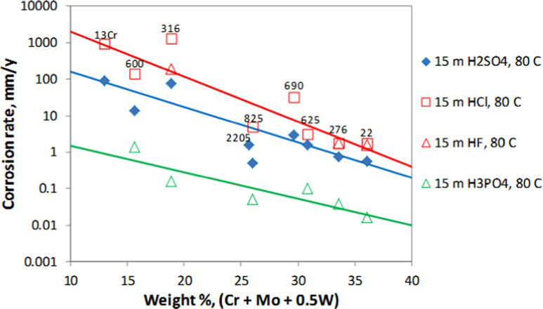
The roles of CO2 and H2S
A rough selection scheme for CRAs was identified by Ueda [14] and reproduced in Figure 12. Takabe et al. [105] established pH, H2S, and chloride limits for a 110 grade of 13Cr–5Ni–2Mo martensitic stainless steel using constant deflection tests at 125 and 175°C. They concluded that for this material, the limits of H2S depended on the chloride concentration and pH. Iannuzzi et al. [24] conducted critical pitting temperature measurements on 13Cr–5Ni–2Mo steel in two different environments containing approximately 0.003 MPa of H2S. The two environments represented produced water containing 30,000 mg L−1 of chloride at a pH of about 4 and condensed water containing approximately 60 mg L−1 chloride at a pH of about 3.5. They found that the pitting temperature, depending on the test technique, were approximately 144 and 121°C for produced and condensed water, respectively. These are below the SCC temperature limits determined by Takabe et al. [105]. Testing time is an issue for both the SCC and critical pitting temperature tests. In the case of SCC tests, as mentioned in the experimental section, the constant deflection tests always leave open the question whether the tests were of sufficient duration [106]. In the case of critical temperature tests, slower test rates may produce higher critical temperatures. It is also possible that higher temperatures than those defined by localised corrosion initiation are needed in terms of maintaining adequate strain rates.
CRA selection scheme identified by Ueda [14].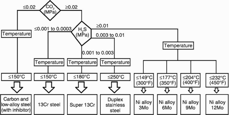
Critical and corrosion potentials for SCC
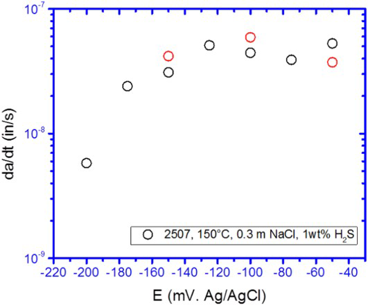
For pH values above the pHd, localised corrosion is a precursor event for SCC [12,107–111]. It is reasonably well established that repassivation potential, E rp or E rcrev represents bounding critical potentials for long-term stable pitting or crevice corrosion [16,102]. Early work on 316L stainless steel, alloy 825, and alloy 22 in chloride solutions showed that SCC occurred only above the E rcrev for the specific alloy–environment condition [30,112]. Others have demonstrated this for similar alloys in sour environments [107–110]. Recent studies of martensitic and duplex stainless steels using CT specimens, wherein a crack is grown at constant K max at a high R-ratio and low frequency have demonstrated the same point (Figures 13 and 14) [18].
Effect of potential on CGR of a 13Cr–6Ni–2Mo martensitic stainless steel CT specimen in N2 deaerated 0.3 M NaCl at 85°C. Also shown as a band of repassivation potentials measured independently on unstressed specimens [18]. Effect of applied potential on CGR of a 25% Cr duplex stainless steel in 0.3 m NaCl with 1 wt-% H2S at a total gas pressure of 1 atm. at 150°C (E rp= ∼−250 mV vs. Ref) [18].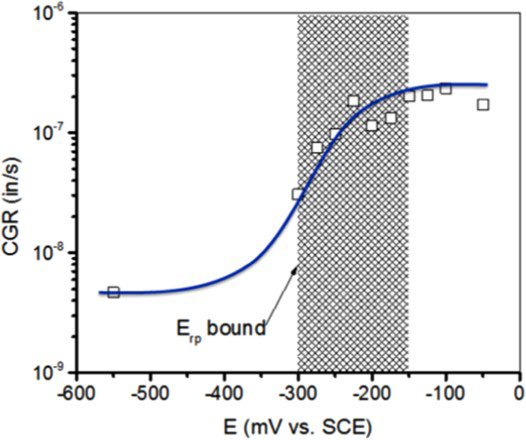
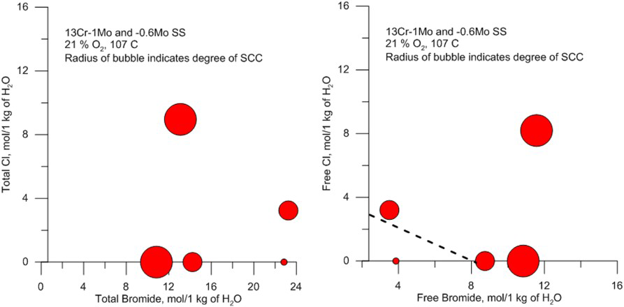
Localised corrosion and SCC in completion fluids
Completion fluids are used in annular space between the production tubing and casing to prevent the reservoir fluids from entering the annular space. The completion fluids are mostly high concentration brines consisting of either bromides of Na, Ca, or Zn, or mixtures of these with chlorides. In some cases, formate salts are used instead of halide salts because of lower corrosion rates in the former. However, in the presence of acid gases, CO2 and H2S, corrosion can occur for the lower alloys in formate brines [113]. The halide brines are more corrosive in general and can cause SCC of some CRAs depending on the composition and temperature [114]. In concentrated brines, speciation is an important consideration as well as pH. In Ca-halide brines, dissociation into free anionic species is essentially complete, whereas in Zn-halide brines significant proportion of the salt is in the form of various complexes. The complexed species do not affect either the SCC susceptibility as shown in Figure 15 [115,116]. The SCC susceptibility in a three-salt brine mixture with a total bromide of 23 molal did not induce any SCC of 13 Cr stainless steel, whereas, if the same mixture is considered in terms of free bromide, the reason for its low susceptibility becomes clearer. Similar conclusions were arrived at by McKennis et al. [117]. In the tests conducted by Skogsberg et al. [116], the presence of H2S exacerbated SCC susceptibility of duplex SS. However, the high-Ni alloys, including some precipitation-hardenable grades did not suffer SCC [116]. Some oxygen scavengers were found to be beneficial as they probably lowered the corrosion potential [116]. It has also been shown that thiocyanate added as a corrosion inhibitor for the carbon steel casing exacerbates the cracking of the CRAs due to an in situ evolution of H2S [114].
Modelling localised corrosion
In the environments in which CRAs are used, H2S exists predominantly as a neutral molecular species. Therefore, modelling the effect of H2S on localised corrosion must consider the competitive adsorption of H2S on the passive film along with Cl− and water. The effect of adsorbed H2S on a number of metals has been studied by Marcus and Protopopoff [118–120]. Single pit experiments conducted by Enerhaug et al. [121,122] have shown that H2S in pits affects the repassivation rate of stable pits. Thus, modelling by Anderko et al. [123,124] considered the competitive adsorption of H2S on the surface of the metal inside the pit. The reactions at the metal surface may further lead to the formation of a metal oxide (MO), metal chloride, and metal sulphide (MS) species, which then undergo dissolution to form metal cations at different rates determined by the potential. The results of the model for two different systems are shown in Figures 16 and 17. The effect of H2S on E rp is complex for the 13Cr alloy. At high H2S concentration (100%), E rp shifts approximately 200 mV from that in the H2S-free condition. In contrast, the effect of low H2S concentration (1%) strongly depends on the chloride concentration. At high-chloride concentrations, E rp of 1% H2S lies between 0 and 100% H2S and follows the similar trend – increase with decreasing chloride concentration. This results from the fact that the adsorption of H2S is strong, therefore, 1% H2S in the gas phase is sufficient to obtain a substantial H2S coverage on the metal surface. At low-chloride concentrations (<0.1 molal), there is no reduction in E rp due to the presence of H2S. Instead, E rp increases dramatically even higher than its level in the H2S-free environment, which indicates a change in mechanism. This effect in the model is a result of the formation of solid MS in competition with MO. The presence of MS has a strong inhibitive effect. The net behaviour of the system is a result of the competition between the acceleration of anodic dissolution due to the adsorption of H2S and the inhibition due to the formation of a solid sulphide phase. The transition between the enhancement and inhibition of localised corrosion is predicted to occur over a narrow range of Cl− activities (between approximately 0.01 and 0.05), which agrees with the experimental data. At very low-chloride concentrations, the E rp lines for 0% H2S and 1% H2S converge. In this region, the potential becomes too high for the MSs to persist. At such potentials, MSs should not be stable because they should oxidise to higher oxidation states of sulphur. Because the E rp enhancement is attributed to the effect of MSs, it should disappear at high potentials. These predictions are consistent with the experimental results reported by Hinds et al. [125]
Model (lines) vs. experimental results of repassivation potential for 13Cr–5Ni–2Mo martensitic stainless steel. All results are at 85°C [123]. Model vs. experimental results for repassivation potential for a 25%Cr duplex stainless steel. All results are at 85°C [123].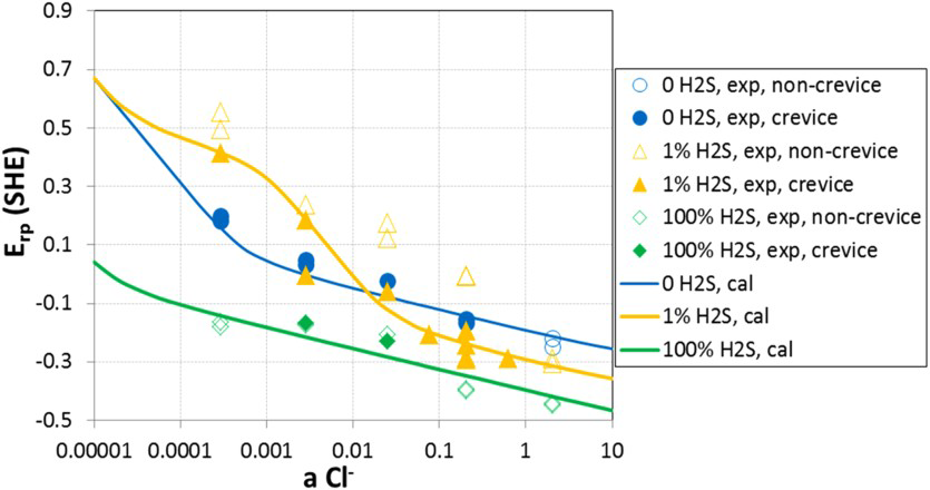
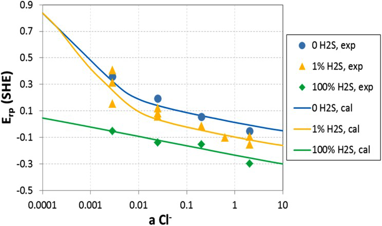
For the duplex stainless steel (Figure 17), in the moderate- and high-chloride concentration (>0.03 molal), the presence of H2S enhances localised corrosion by decreasing E rp values. Both E rp for 1 and 100% H2S are largely parallel to the line of nitrogen and shift to more negative direction successively. The high H2S concentration has a stronger enhancement on localised corrosion than the lower concentration. Nevertheless, the enhancement effect of 1% H2S diminishes in the low-chloride region. The complex behaviour of 1% H2S reflects the competition effects between oxide and sulphide formation. In addition, the two-phase structure of 2507 duplex adds behaviour complexity. Sulphide effects tend to be stronger in the weak passivity, while sulphide effects should disappear at higher potential where sulphides are not thermodynamically stable. Again, the agreement between the model and experiments is reasonable. The corrosion potential in downhole environment is determined by pH, H2S, and S0 [12]. In some cases, air leakage into the annular space has been reported leading to an increase in corrosion potential due to oxygen reduction reaction [114]. The increase in corrosion potential due to H2S is shown in Figures 18 and 19 [124].
Corrosion potential of S13Cr as a function of temperature in Cl−+H2S systems. Total pressure of H2S+N2 is 25 atm. Symbols are experimental data and lines are model results [124]. Corrosion potential of 2535 as a function of temperature in Cl−+H2S systems. Total pressure of H2S+N2 is 25 atm. Symbols are experimental data and lines are model results [124].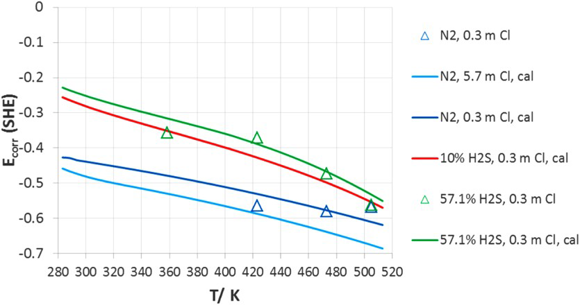
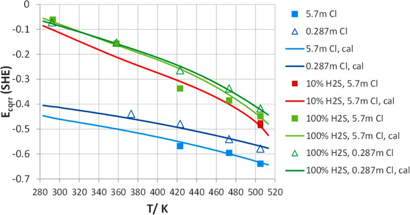
The effect of H2S on increase in corrosion potential arises from two mechanisms: the decrease in pH and the direct cathodic reduction of dissolved H2S [124]. The combination of decrease in repassivation potential and increase in corrosion potential due to H2S would be expected to result in localised corrosion above a critical chloride concentration in the presence of H2S. This is indeed consistent with experimental results [124,125].
Effects of surface condition on SCC
The effect of surface preparation on SCC of austenitic stainless steels has been known since the 1940s [126]. Rougher surfaces increase metastable pitting of stainless steels [127–129], but do not affect stable pitting and the repassivation potentials [128,130]. The chemistry inside crevices on rougher surfaces are not as concentrated and acidic as under crevices on smoother surfaces [15]. The adverse effect of surface roughness in the direction perpendicular to the stressing direction on SSR testing in H2S environments has been demonstrated by numerous authors [29,32]. Hinds et al. [130] showed that type 316L stainless steel heat tinted at 800°C showed greater tendency to initiate pits and cracking in an aqueous environment containing 50,000 ppm Cl−, pH 4.5, and 1% H2S in CO2 at 110°C. The initiation of cracking was not dependent on surface roughness, but was shown to originate at pits. The difference in cracking susceptibility of the heat-tinted specimens was evident in the 90-day test vs. the 30-day test. Post-test examination of the specimens showed that mechanical defects created by grinding showed a greater propensity for pitting than inclusions. Microcrack clusters in chloride environments on duplex stainless steels was observed to be associated with dealloying layers in ferrite from grinding [130]. The stable growth of SCC from the transformed layers at the surface has not been studied.
Summary and future directions
Since mid-1970, the use of CRAs in oil and gas production and the knowledge regarding their selection has continued to expand. The factors leading to the localised corrosion and environmentally assisted cracking of CRAs are generally recognised. These factors include (i) the depassivation pH below which active corrosion occurs, (ii) the corrosion potential, (iii) the critical potential of an alloy in an environment for localised corrosion, (iv) the hydrogen transport and solubility, (v) the local strain rate due to loading and defects, and (vi) the critical strain rate required to have a stable SCC or HE. It is possible, in principle, to project all the measurable parameters for a given alloy and production condition in this factor space. This review builds upon previous extensive reviews of the field in presenting some of these factor effects:
The role of alloying and microstructural features, such as coherent precipitates, on micro-plastic deformation mode is highlighted, specifically focusing on planar deformation mode as a trigger for building locally high stresses. The planar deformation mode has a detrimental effect on near-constant load SCC/HE, but has a beneficial effect on fatigue. In many actual structures, there is a cyclic loading component superimposed on a base loading at relatively low frequencies. The effect of planar deformation mode on such ripple loading needs further study. Many of the conventional metallurgical parameters that determine SCC/HE can be understood in terms of critical local stresses brought on by local plasticity. Thus, higher strength, which is mostly (but not always) detrimental to HE and SCC, leads to high build-up of local stresses due to increased barriers to dislocation movement. Precipitation hardenable alloys have shown varying resistance to SCC because of different combinations of matrix SFE, mismatch stresses, etc. The role of strain rate and the critical strain rate for EAC needs further characterisation. The role of alloying elements, second phase precipitation, and environmental composition on the corrosion and critical potentials is reviewed. For pH values above the depassivation pH, localised corrosion is the mode of failure, provided the critical potentials are below the corrosion potential. Significant progress has been made in being able to model the critical (repassivation) potential and corrosion potential, as well as determine the depassivation pH as a function of environmental and alloying factors. The role of H2S in stabilising the pit dissolution process needs further investigation. In situ analytical techniques can contribute significantly to such an understanding. The repassivation potential acts as a threshold for SCC, provided the crack tip strain rate is above the critical strain rate. The crack tip strain rate depends on external factors, such as magnitude of applied stresses and temperature. The critical strain rate is dependent on microstructural features, especially micro-plastic deformation mode as mentioned previously. The combination of these factors provides a framework for understanding SCC of CRAs. The role of surface condition on localised corrosion and their transition to SCC is being characterised using sophisticated microstructural and surface analytical tools. These studies have indicated that surface mechanical damage and heat tint from welding can increase the susceptibility to early stage localised corrosion and SCC. However, the transition from the early stage cracking to stable cracking in oil and gas environments is important to understand. For thick sections as well as bolting, fracture mechanics-based designs and crack growth management approach are becoming of interest.
It is well recognised that there are uncertainties in environmental chemistry, temperature, metallurgical parameters, experimental data, and models. This means that a probabilistic approach is the most appropriate way forward to make decisions. Unfortunately, most risk-based approaches in oil and gas production systems rely on subjective ranking methods, statistics of past failures, or are simply based on consequences. These methods, while attractive from the perspective of simplicity and ease of use, are not satisfactory. The risk ranking methods are usually dominated by consequences and are not sufficiently rigorous in treating probabilities. The statistical methods do not treat the various causative factors that lead to failures and therefore proper risk mitigation methods cannot be evaluated. Probabilistic assessment of EAC limits has been attempted in the past [131], but have focused more on the mechanical aspects of the problem. A more holistic approach to probabilistic failure assessment can take advantage of the Bayesian network approach [132], in which the factors contributing to EAC are linked through probabilities using Bayes’ theorem. For example, the probability of EAC is related to the probabilities of strain rate exceeding a critical strain rate, the probability of corrosion potential exceeding a critical potential, etc. The probabilities of these factors are, in turn, linked to the probabilities of the occurrence of factors influencing their values. A major advantage of the Bayesian network approach is that it captures our understanding of the whole system including expert knowledge, laboratory data and field experience. As sensors and various ‘smart’ devices are increasingly employed in oil and gas production systems, the Bayesian network and other information analytics will be essential to help us make risk-informed decisions.
Footnotes
Acknowledgement
The authors wish to acknowledge the support of the members of the Joint Industry Project, Chevron, ConocoPhillips, Petrobras, Sumitomo Metals Nippon Steel, Vallourec, JFE Steel, Sandvik, and DNV GL, for some of the data presented in this review paper. The support of DNV GL in preparing this manuscript is also gratefully acknowledged.
Disclosure statement
No potential conflict of interest was reported by the authors.