
Abstract
A novel, low-alloy steel has been designed for use in the oil and gas industry. Its high strength and hydrogen trapping potential are derived from a martensitic microstructure containing a dispersion of fine vanadium–molybdenum alloy carbides that evolve during tempering. In this second paper, the effect of quench rate from austenitisation and tempering conditions are investigated with respect to the microstructure. The alloy loses its tempering resistance following slow-cooling from austenitisation as a result of MC precipitation, leading to vanadium depletion and significant M C coarsening. This is predicted using computer simulation and confirmed by high energy X-ray diffraction, combined with electron microscopy.
Keywords
Introduction
High-strength steel is required to exploit subsea oil and gas reserves that operate at an elevated temperature and pressure. However, high-strength steel exacerbates the susceptibility to hydrogen embrittlement [1–5]. This is especially problematic with a hard microstructure, thermally induced residual stresses and a constant supply of hydrogen that is generated during the service life of the material. For this reason, a quench and tempered steel containing alloy carbide precipitates has been designed, that is capable of trapping diffusible hydrogen and rendering it harmless. Full details are available in Part 1 [6], which includes the mechanical properties and hydrogen trapping capacity when compared with a commercially available F22 grade steel.
In the new alloy, designated HT10, a fine dispersion of V–Mo–Cr carbides throughout the martensite provide the mechanism for both strengthening and hydrogen trapping [6]. These precipitates must be sufficiently small to remain coherent with the surrounding matrix and produce the strain fields [7] necessary to act as trap sites [8–11]. The V–Mo–Cr carbides that form in HT10 are expected to be non-stoichiometric and carbon deficient [12–14], containing up to 30 wt-%Mo [15]. It has been shown that the morphology of the carbide is spherical in nature if formed during austenitisation and is in fine platelet form when precipitated during tempering [6]. Because the alloy undergoes a series of thermal cycles during manufacture, its precipitation behaviour has to be known to ensure the correct particle size and distribution that provide adequate level of hydrogen trapping capacity. This paper investigates the effect of the cooling rate from austenitisation along with tempering conditions and their combined influence on the alloy carbide precipitate evolution.
Experimental procedure
 C for 0.5 h. The PAGS were determined using the linear intercept method and transmission electron microscopy (TEM) was conducted on electro-polished foils with an FEI TECNAI Osiris operating at 200 kV. The chemical composition of the precipitates was determined by energy dispersive spectroscopy (EDS).
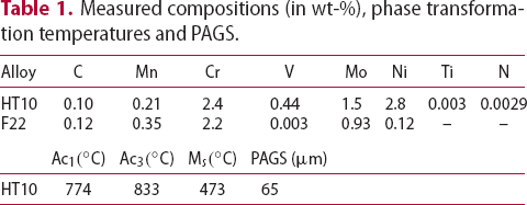
Measured compositions (in wt-%), phase transformation temperatures and PAGS.
Effect of cooling rate on tempering hardness
Specimens were prepared from the as-received hot-rolled plate and austenitised at 1050 Effect of cooling rate from austenitisation on hardness for HT10 steel tempered at 600 C for 0.5 h to dissolve most of the carbides that may have formed. Cooling rates of 3400, 120 and 60
 C h−1 were adopted, followed by tempering at 600
 C for various times. The hardness profiles as a function cooling condition (Figure 1) suggest that HT10 has a high degree of hardenability, which is necessary when manufacturing thick sections. However, the alloy loses its tempering resistance following slower cooling from austenitisation.
 C.
C.
Synchrotron X-ray diffraction
Following thermal treatment, 2 mm diameter and 2.5 mm long specimens were machined for high-energy X-ray diffraction (XRD). The experiment was performed on the I12 beamline at Diamond Light Source, UK. A Debye-Scherrer geometry with sample rotation was employed to improve intensity and avoid the effects of preferential orientation. The instrument was calibrated against a cerium dioxide standard and the X-ray wavelength was 0.1559 Å. The data were analysed with Materials Analysis Using Diffraction (MAUD) [16] software, which was used to calculate the retained austenite content and lattice parameters. The carbon concentration of the austenite was then estimated from the lattice parameter, Onink et al. [17]. The martensite dislocation density was evaluated using the approach detailed by Williamson et al. [18,19].
Synchrotron XRD data were analysed using Rietveld refinement [20,21]. No stable fits with carbides were possible due to their minimal volume fractions, therefore, only austenite and martensite were included. The following variables were included in the refinement: the background function (fifth-order polynomial), incident X-ray intensity, austenite phase fraction, lattice parameter, texture (eighth-order spherical harmonics), crystallite size and microstrain for both austenite and martensite. Isotropic microstrain and crystallite size were assumed.
Figures 2(a) and 3(a) present the obtained X-ray diffractograms for fast-cooled (3400 (a) X-ray diffractogram of HT10, austenitised and cooled at 3400 (a) X-ray diffractogram of HT10, austenitised and cooled at 120 C h−1) and slow-cooled (120
 C h−1) samples followed by tempering at 600
 C for various times. Figures 2(b) and 3(b) highlight a magnified section of the spectrum where the weaker but significant contributions from MC
1
and M
C for various times. Figures 2(b) and 3(b) highlight a magnified section of the spectrum where the weaker but significant contributions from MC
1
and M C
2
can be resolved. Although the peak positions of MC and M
C
2
can be resolved. Although the peak positions of MC and M C are the same for both fast- and slow-cooled specimens, the peak broadening behaviour is different. The MC and M
 C peaks observed after fast-cooling and 24 h tempering are shorter and broader, indicating that a smaller particle size is produced.
  Ch−1; (b) magnified section of (a).
 Ch−1; (b) magnified section of (a).
Retained austenite is detected in the untempered condition for both cooling rates but it is not present following tempering for 1 h. It is expected that retained austenite would transform to ferrite and cementite during reheating and tempering. During reheating and tempering, cementite is expected to form first from supersaturated martensite, cementite would then dissolve and form alloy carbide during further tempering at 600 C indicated by the increase in intensity of the MC and M
 C peaks. A very small austenite (
 ) peak remains after tempering for 1 h and the peak increases in size as the tempering time progress. This is due to the precipitation of nickel-rich austenite (
 ) as reported in nickel-added steel [22–24].
Figure 4 highlights the effect of cooling rate from austenitisation and tempering time on the martensite (b) lattice parameter, (c) tetragonality and (d) dislocation density. Figure 4(a) provides an indication of the goodness-of-fit for the data refinement, evaluated using the weighted profile R-factor ( (a) Weighted profile R-factor  ), where a lower value corresponds with improved fitting. The
  increases with tempering time due to higher carbide contents, that were not included in the Rietveld analysis.
  ; (b) lattice parameter; (c) tetragonality; (d) dislocation density.
The martensite loses its tetragonality (ratio of the lattice parameters, c/a) with prolonged tempering times and tends towards a cubic structure as carbon vacates the interstitial sites [25,26]. Both fast- and slow-cooling resulted in similar hardnesses, despite lower dislocation density in the latter (Figure 4(d)). Samples cooled at both rates show a gradual reduction in dislocation density with increased tempering time.
A larger austenite lattice parameter is observed in the slow-cooled specimen (Figure 5), which is consistent with the extended time allowed for carbon to partition into the austenite during martensitic transformation [27]. (a) Lattice parameter and calculated carbon content of austenite for untempered HT10 steel.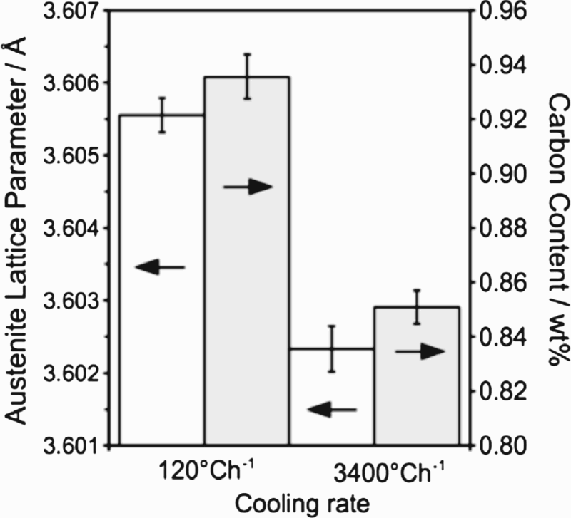
 C were calculated from the measured d-spacing at [111]
 ,
,  and
and  reflection, respectively. The lattice parameters of the molybdenum-rich carbides (M
 C) are very close to the reported values [28,29]. The measured lattice parameter of MC in this work is comparable to some literature values [30–32], whilst there are slight differences (but less than 0.6%) when compared to other data [7]. There is no evidence from the obtained synchrotron XRD spectra that the monoclinic V
 C
C [13] is formed.
Space group and measured unit cell of the phases identified with synchrotron XRD.
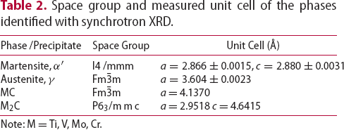
Note: M=Ti, V, Mo, Cr.
Precipitate characterisation with TEM
Microstructural characterisation in Part 1 identified fine V–Mo–Cr-rich carbides distributed throughout a martensitic matrix for rapidly cooled and tempered HT10 steel. In this work, additional precipitates are observed and distinguished in terms of their structure, shape and composition. When subjected to slow-cooling from austenitisation (1050 Microstructures following slow-cooling (120 C), a martensite lath matrix is still observed, Figure 6(a), indicating low carbon content in austenite before martensite transformation. However, the partition of carbon is also evident, where Figure 5 shows a high carbon content in the retained austenite in slow-cooling steel. The evident is further supported by the detection of twin martensite in Figure 6(b), which is commonly associated with high-carbon martensite transformation.
  Ch−1); (a) lath martensite matrix, (b) twin martensite.
 C at 600
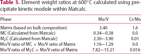
 C were calculated using the precipitate kinetic module within Matcalc, Table 3. In order to incorporate the material surrounding the precipitates within the interaction volume, the carbide weight ratio was multiplied by that of the matrix
3
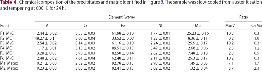
. In this work, a precipitate is considered to be an MC carbide if the Mo/V weight ratio is
C were calculated using the precipitate kinetic module within Matcalc, Table 3. In order to incorporate the material surrounding the precipitates within the interaction volume, the carbide weight ratio was multiplied by that of the matrix
3
. In this work, a precipitate is considered to be an MC carbide if the Mo/V weight ratio is  . M
. M C type carbides are defined by a Mo/V ratio between 7 and 16. The chemical compositions of the identified precipitates based on the discussed Mo/V ratio criteria were shown in Table 4.
Element weight ratios at 600C calculated using precipitate kinetic module within Matcalc.
Chemical composition of the precipitates and matrix identified in Figure 8. The sample was slow-cooled from austenitisation and tempering at 600C for 24 h.
As in Part 1, MC carbide precipitation within the martensite laths were also been detected, Figure 7 shows a fine MC carbide that possesses a Baker and Nutting orientation relationships within a martensite lath in a high-resolution transmission electron microscopy (HRTEM) image. Large M Small MC precipitate observed after slow-cooling from 1050 Slow-cooling and tempering at 600 C precipitates were also observed at pre-existing MC sites, following tempering at 600
 C for 24 h. Such M
 C particles nucleation nature has been reported in the literature [15,33,34] and is identified by the characteristic ‘H’ morphology. The local depletion of vanadium following MC precipitation and replenishment with molybdenum from the solid solution leads to such precipitation phenomenon. Elongated M
 C particles can also form at the grain and martensite lath boundaries (e.g. P6 in Figure 8(b)).
  C and tempering at 600
 C for 24 h; (a) HRTEM image (b) FFT diffractogram of (a) showing that the alloy carbide possesses Baker and Nutting orientation relationships with martensite lath.
 C for 24 h produces large M
 C precipitates; (a) on an existing MC particle with fine carbides in the martensite lath, (b) at grain/lath boundaries.
The measured Cr/Mo ratio of both MC and M C were also included in Table 4. Comparing the EDS measured and calculated values, it is evident that larger amount of Cr partition into both MC and M
 C than has been reported by others [12,35,36].
TEM micrographs shown in Figure 9 reveal the austenite ( Fast-cooled sample, tempered at 600 ) identified during synchrotron XRD, which is enriched in Cr, Ni and Fe. In this figure, fine V–Mo–Cr-rich carbides were found in the surrounding of a larger precipitated austenite (
 ).
).  C for 10 h. Cr, Ni, Fe-rich precipitates with some V, Mo, Cr carbide. The Cr, Ni, Fe-rich precipitation is austenite (
 ), while V, Mo, Cr-rich precipitate is carbide.
MC, M Ti-rich particle encapsulated by V, Mo and Cr following slow-cooling (120 C and precipitated austenite (
 ) were all identified using TEM/EDS mapping. These observations correlate with the phases recorded during synchrotron XRD. Other large particles identified in very low concentrations consisted of a Ti-enriched core surrounded by a V–Mo–Cr carbide shell, Figure 10. Ti-rich precipitates that formed during casting and reheating before hot rolling remain undissolved at the high austenitisation temperature, while the V–Mo–Cr carbide shell would form preferentially on the Ti-enrich core at lower temperature during slow cooling. Epitaxial precipitation is common in Ti-V containing steel and its formation mechanism is explained elsewhere [37].
  C h−1).
Thermo-kinetic simulation
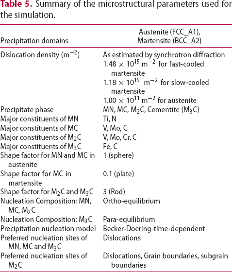
 C [43]. Grain boundaries, subgrain boundaries and dislocation are judged to be the nucleation sites for M
 C, based on TEM observation.
Summary of the microstructural parameters used for the simulation.
Results for the numerical simulations are based on the thermal treatment in Figure 11. Cooling from 1200 (a) Heat treatment cycle used for the simulation. (b–d) Precipitation kinetic in austenite during cooling from austenitisation; (b) phase fraction, (c) mean radius and (d) number density. C is used to simulate high-temperature precipitation that may typically form during casting and hot rolling. Austenitisation is performed at 1050
 C for 0.5 h, which is sufficiently high to dissolve the majority of MC carbides. Two cooling rates were applied (3400 and 120
 C h−1), followed by tempering at 600
 C for a maximum of 24 h.
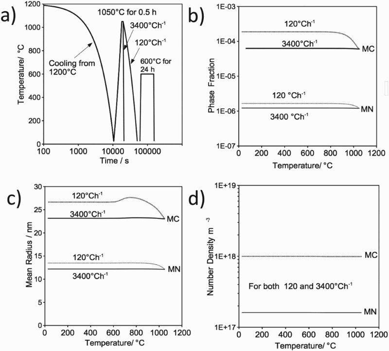
The effect of cooling rate from austenitisation, on the precipitation as a function of temperature, is presented in Figure 11(b)–(d). Due to its stability and the fact that all nitrogen has been tied up by titanium, the phase fraction and mean radius of MN are not influenced by the cooling rate. However, the phase fraction and mean radius of MC carbide increases with decreasing temperature (down to 800 C) during slow cooling. Different cooling rates are not expected to alter the precipitate nucleation site and hence the number density should remain constant for both MN and MC, Figure 11(d).
Element concentrations in martensite before and after tempering.
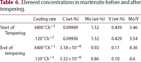
Figure 12 shows the precipitation kinetics in martensite during cooling from austenite. The simulation assumed that the martensite transformation occurred completely at the start temperature, although it is athermal in nature [44]. A slow-cooling rate encourages precipitation of both MC and M Precipitation kinetic in martensite during cooling from austenitisation; (a)–(b) phase fraction; (c)–(d) mean radius; (e)–(f) number density versus time. C, where greater phase fraction, larger precipitate size and higher number density were observed.
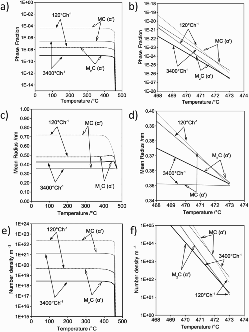
The simulated tempering of HT10 steel at 600 Precipitation kinetic during tempering at 600 C suggests that the MC precipitate reaches its maximum phase fraction as soon as the tempering temperature is obtained (Figure 13). The rapid increase in M
 C phase fraction, observed in the slow-cooled condition, is caused by the higher Mo/V ratio present when tempering begins. Matcalc simulations suggest that M
 C is present at equilibrium and even at the beginning of the tempering cycle, although it is not detected by synchrotron XRD.
  C; (a) phase fraction, (b) mean radius, (c) number density versus time. Hour line markers indicate time at 600
 C.
C.
Specimens cooled at 3400 C h−1 allow finer precipitates (8 nm) to stabilise when tempered for less than 10 h. Slow cooling increases the stabilised MC precipitate radius to 15 nm. Significant coarsening is observed after 10 h for both MC and M
 C in the fast-cooled condition and MC in the slow-cooled condition. At this point, the carbides are expected to lose coherency with the matrix.
MC precipitates increase in radius, while decreasing their phase fraction and number densities after 10 h tempering. This indicates precipitation coarsening and dissolution. Both the radius and phase fraction increase simultaneously for the M C carbide, suggesting that it is more stable compared with MC. Ultimately, MC will be consumed by M
 C following long-term tempering.
The simulation predicts that a slow-cooling rate from austenitisation increases MC formation in austenite, which promotes both MC and M C carbide precipitation (nucleation) in martensite during cooling. Coupled with the increased Mo/V ratio in the matrix, this leads to a more rapid M
 C coarsening rate during tempering. Furthermore, a slow-cooling rate increases the radius and reduces the number density of MC carbide during tempering. For these reasons, HT10 is more temper resistant in the fast-cooled condition.
In order to maintain a tough yet high-strength steel, it is important that any cementite present undergoes dissolution and is replaced by the alloy carbides. Figure 14 shows the calculated cementite precipitation kinetic during tempering. The phase fraction of cementite stabilises during reheating but drops to a very low level once the tempering temperature is achieved. No cementite peak was detected using synchrotron XRD after 1 h tempering. Cementite precipitation kinetic during tempering at 600 C; (a) phase fraction, (b) mean radius, (c) number density versus time. Hour line markers indicate time at 600
 C.
C.
Thermodynamic equilibrium calculation
The equilibrium phases as a function of temperature were calculated using Matcalc with the mc_fe_v2.000_prebeta_012 database as shown in Figure 15. M (a) Equilibrium phase weight per cent of HT10 as a function of temperature. (b)–(d) The atomic fraction of (b) M(C,N), (c) M C is stable below 700
 C compared with M(C, N). MnS and a small quantity of austenite appear below 400
 C. For the M(C, N) phase, Ti and N are the major elements at high temperature, while V, Mo and C are present on cooling. Figure 15(d) shows that the austenite (
 ) that may be present at low temperature has a high nickel and manganese content. However, Ni, Cr and Fe are observed within the precipitated austenite (
 ) in the TEM work. Further work is necessary to clarify the precipitated austenite stability since the precipitate is detected during tempering at 600
 C, while the thermodynamic calculation indicates that the precipitate is stable below 400
 C. Likewise, the composition variation in MC, M
 C and precipitated austenite (
 ) between experiment and calculation would also require further investigation, bearing in mind the experiment performed in this work is not in equilibrium.
  C, (d) austenite (
 ) as a function of temperature.
Discussion
The particle size, shape, number density, volume fraction, lattice parameter and composition of MC and M C carbide have been characterised using TEM, synchrotron XRD and computer modelling. This has allowed the microstructural changes that occur during tempering to be explained in this newly designed steel.
During tempering of HT10, both MC and M C (
C ( , V, Cr, Mo) can form. Depending on the cooling rate from austenitisation, the precipitation kinetics are affected as well as the resistance to softening. Although equilibrium calculations predict that M
 C carbide is more stable, it can only be identified following an extended tempering time. Furthermore, its coarsening rate is affected by the MC carbide that precipitates during cooling from austenitisation. Precipitate coarsening, together with the obtained dislocation density following cooling from austenitisation, determine the number density of MC carbide during tempering.
The large MC carbide that forms in austenite during slow cooling was identified with TEM, computer simulation and additionally by synchrotron X-rays. Careful observation of X-ray spectra indicates that the MC diffraction peak is prevalent for all tempering conditions, although the fast-cooled specimen produces a peak after a few hours at temperature. The high number density of fine MC precipitate (fast-cooled sample) is predicted using the computer simulation and confirmed by diffraction where a small, broad peak is recorded. The large M C peak observed for the slow-cooled sample after 24 h tempering is due to precipitation and coarsening, which occurs more rapidly under these conditions.
Regarding M C precipitation, which is only detected after tempering time of 24 h at 600
 C, there is a discrepancy with MatCalc calculation (Figure 13) which indicates earlier precipitation during tempering. However, the calculations rely on nucleation sites assumed to be dislocations, grain boundaries and subgrain boundaries. The number density of such sites should be regarded as a fitting parameter since the number of nucleation sites per unit length of dislocation or boundary is uncertain. Furthermore, it has been observed in TEM that M
 C nucleate preferentially on MC precipitation, which is not modelled in Matcalc. Additionally, the early fraction of M
 C in the calculation is
  which could be difficult to detect experimentally. It may also be necessary to update the thermodynamic data with respect to the chemical composition of MC and M
 C, where a significant amount of molybdenum and chromium has been detected in the precipitates. Similarly, the thermodynamic data on the temperature stability of precipitated austenite precipitated in nickel containing martensite is also need updated.
Conclusions
Both MC and M The dislocation density in the martensite, following austenitisation, influences the MC precipitate number density. The fast-cooled sample yielded a precipitate density an order of magnitude higher than the slow-cooled. The loss of tempering resistance in HT10 following slow-cooling from austenitisation is due to the low number density of MC precipitates and significant M
 C precipitates are present in HT10 after tempering at 600
 C. The initial Mo and V concentrations, and Mo/V ratio caused by MC precipitation in austenite during cooling, resulted in faster precipitation kinetic of M
 C.
C. C carbide coarsening.
Footnotes
Acknowledgments
The authors would like to acknowledge the technical support from BP through the BP International Centre for Advanced Materials (BP-ICAM) which made this research possible. The provision of synchrotron beam time by the Diamond Light Source is also gratefully acknowledged.
Disclosure statement
No potential conflict of interest was reported by the authors.
1
Vanadium rich carbide with face-centred cubic structure, the exact chemical composition of this carbide is not known and may vary with bulk chemical composition and heat treatment. Most commonly reported as MC and MC.
2
Molybdenum-rich carbide with hexagonal structure. ‘M’ represents metal atoms which include titanium, niobium, vanadium and molybdenum.
3
Based on the damage region observed after EDS measurement in this work, the diameter of the incident beam is estimated to be 30 nm in diameter.
References
 C
C precipitates on the hydrogen induced mechanical degradation in Fe-C-V alloys
 C precipitates in isothermal tempering of high Co-Ni secondary hardening steel