
Abstract
The French national radioactive waste management agency (Andra) is in charge of studying the disposal of high level wastes (HLW) in deep geological repositories. The reference concept for HLW disposal cells consisted of a multi-barrier system: horizontal boreholes drilled in the Callovo Oxfordian (COx) claystone, cased with carbon steel (C-steel) and containing C-steel overpacks with the nuclear waste packages. Mechanical strength is required for the metallic structures to ensure safety. This study presents the work performed on C-steel to assess in situ mechanical loading, long-term mechanical behaviour based on modelling and environmentally assisted cracking (EAC) susceptibility. The results from in situ experiments have demonstrated anisotropy of the mechanical loading of the casing. Long-term calculations revealed local plastic strain after a few years to a few decades, which highlighted the need to assess the potential risk of EAC. Eventually, the results on EAC assessment in the COx claystone confirmed that the microstructure of the casing and overpack plays a key role on the mechanical resistance.
This paper is part of a supplement on the 6th International Workshop on Long-Term Prediction of Corrosion Damage in Nuclear Waste Systems.
Introduction
The French national radioactive waste management agency (Andra) is in charge of studying the disposal of high level wastes (HLW) in deep geological repositories. The reference concept for HLW disposal cells consisted of horizontal boreholes (∼0.9 m in excavated diameter), drilled in the Callovo Oxfordian (COx) claystone, containing C-steel casings (∼0.76 m in outer diameter), inside which C-steel overpacks (∼0.635 m in outer diameter) would be emplaced. The casing must be sufficiently robust to allow the retrieval of the waste packages for at least a century. In addition, the overpack should be water tight in order to prevent water from reaching the glass matrix during the thermal phase (time needed for the temperature of the glass matrix to decrease below 50°C depending on the type of wastes). In clay environment, C-steel susceptibility to EAC in clay environment was demonstrated for pipeline used in oil & gas industry [1]. Indeed, two modes are considered: on the one hand, intergranular stress corrosion cracking (IGSCC) in neutral-alkaline pH under anaerobic or slightly aerobic conditions, and on the other hand, transgranular stress corrosion cracking (TGSCC) under low pH and anaerobic conditions. TGSCC is enhanced by hydrogen induced cracking. IGSCC is more likely to occur on metal surface covered by corrosion layers and the potential range of concern is the active/passive transition domain. IGSCC and TGSCC are usually promoted by dynamic stresses (which is not expected in repository conditions). Nevertheless, constant stress (such as residual stress or stress applied by the host rock to the casing) need to be considered as well. In addition, previous work revealed that C-steel P265 grade may exhibit some susceptibility to EAC in COx claystone [2,3] due to its banded ferrite–pearlite microstructure that promoted chemical preferential attack (galvanic coupling). This result is in agreement with the role of the microstructure in EAC resistance [4,5]. Therefore, Andra put significant effort to select C-steels with appropriate microstructure (homogeneous microstructure, low inclusions content …) and mechanical properties (hardness below 250 HV [6]) for the casing and overpack and thus overcome EAC. Research is conducted on demonstrator in the Meuse/Haute-Marne underground research laboratory, as well as in laboratory equipped for EAC investigation. Moreover, modelling is run in parallel for long-term prediction at the repository timescale.
This study presents the work performed on C-steels to assess:
short -term in situ mechanical loading of the casing taking into account the real environment under repository conditions; This study was launched to identify the stress applied by the host rock on the casing and the resulting plastic strain that may lead to EAC; long-term mechanical behaviour of the casing based on modelling; EAC susceptibility for three selected C-steel materials in clay environment (COx) at 90°C (maximum expected temperature in the disposal cell walls).
Materials and method
In situ experiment on mechanical loading of the casing
In situ mechanical loading was investigated on a full scale HLW cell demonstrator drilled in the Meuse/Haute-Marne Underground Research Laboratory (URL) at Bure [4]. In situ stress field at the Meuse/Haute-Marne URL is anisotropic [7]. The major stress (σ H) is about 16 MPa and horizontally oriented while the vertical stress (σ v) and the horizontal minor one (σ h) are about 12 MPa. The drilling of the borehole was performed by a micro-tunnel boring machine [8]. Then, the borehole was equipped with a 40 m long casing (grade API 5L X65). The cell demonstrator was parallel to σ H, in order to limit the anisotropy of the radial load applied by the rock on the casing. The initial annular space was 20 mm. The casing outer diameter and thickness were 700 and 20 mm, respectively. Four sections of the casing were equipped with displacement sensors and strain gauges along the casing (at 7, 15, 25 and 35 m deep) to estimate the main characteristics of the short-term mechanical load on the casing at different locations. The data were monitored via a data acquisition system for about 4 years.
Modelling on long-term behaviour of the casing (reference grade API 5L X65)
The long-term elastic–plastic behaviour of the casing has been determined by numerical simulations performed by the Technological University of Troyes. An elastic–plastic behaviour model with mixed hardening (isotropic and kinematic) strongly coupled with ductile damage formulated in the classical framework of thermodynamics of irreversible processes with state variables at the macroscopic scale was considered for the API5LX65 steel. A weak multi-physical coupling between damage and corrosion was also considered to account for the progressive degradation of the mechanical properties according to the constant and homogeneous corrosion rate on inner and outer surfaces of the casing. The fully coupled constitutive equations have been implemented into ABAQUS FE code. External loadings applied by the rock have been determined from coupled thermo-hydro-mechanical calculations performed by external laboratories (ISL and ITASCA). An example of loading spectra is given in [9]. Several scenarios have been simulated by applying different parameter sets (external pressure, casing depth, corrosion rate, initial annular space between the casing and the rock, etc.).
EAC assessment for the casing and overpack
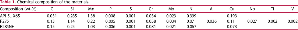
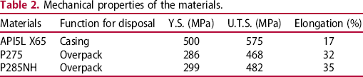
The chemical composition and mechanical properties of the materials are given in Tables 1 and 2, respectively. Their microstructures are presented in Figure 1.
Microstructures of the materials after polishing and etching (10% nital): API 5L X65 grade with a ferrite microstructure (left); P285NH with a ferrite–pearlite microstructure (middle); P275 with a banded ferrite–pearlite microstructure (right). Chemical composition of the materials. Mechanical properties of the materials.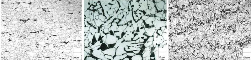
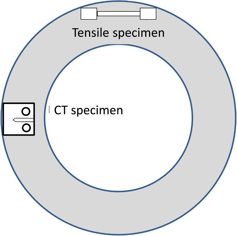
A 50 L testing glass cells was used for this study. It contained 50 wt-% of synthetic clay pore-water as well as 50 wt-% of ground COx claystone which formed a deposit at the bottom of the cell. The operating temperature was set at 90°C to consider the maximum temperature in service. Gas containing H2 (0.06 bar) and CO2 (0.0015 bar) was continuously injected above pore-water to maintain anoxic conditions and simulate in service conditions. All the specimens were machined from mock-ups to take into consideration the thermo-mechanical (TM) history of the materials while testing. They were taken parallel to the circumferential direction of the mockup (see Figure 2), corresponding to the direction of maximum tensile stress in service. Crack initiation tests were performed using spring loaded devices to apply a constant load below (∼80% σ y) and above the yield strength (∼105-110% σ y). The load applied to the notched tensile specimen was calculated by taking into consideration the cross section at the root of the notch. Crack propagation investigation involved fatigue pre-cracked CT specimens tested under stress intensity factors between 15 and 40 MPa Schematic diagram showing the sampling orientation. by using a spring device.
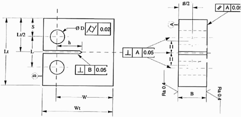
Figures 3 and 4 show schematic diagrams of the specimens used for crack initiation (notched tensile specimen) and crack propagation (compact tensile specimen) experiments, respectively. Once loaded, CT and tensile specimens were immersed at open circuit potential both inside the claystone deposit and in the COx pore-water in order to investigate two possible cases: a direct contact of the casing with the host rock and a contact of the casing or overpack with seepage water. The time of exposure was 8000 h for crack initiation testing and 4000 h for crack propagation testing.
Schematic diagram of the tensile notched specimen (left) and detail of the notch (right). Schematic diagram of compact tensile specimen (CT10):h = 8 ± 0.2; B = 10 ± 0.05; D = ØH7; e = 1.2 ± 0.1; wt = 25 ± 0.1; Lt = 24 ± 0.1; S = 6.5 ± 0.1; L = 11 ± 0.05; W = 20 ± 0.05.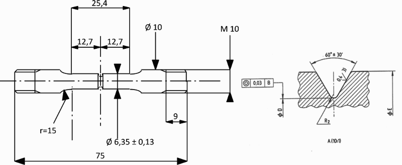
After their removal from the test cell, CT and tensile specimens were subjected to observations by using optical microscopy (OM) and scanning electron microscopy (SEM) when necessary.
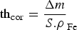
In addition, coupons with a total surface area of 25 cm2 were used to measure the mean corrosion rate (CR) by using gravimetric measurements (weight loss). Once removed from the glass testing cell, the coupons were rinsed with ethanol and dried to prevent post-removal oxidation. Gravimetric measurements were performed by measuring the weight before and after soaking the coupons in a solution of 50 wt-% H2O/50 wt-% HCl (37 wt-% HCl concentration) containing 5 g L−1 hexamethylenetetramine ((CH2)6N4) as an inhibitor of iron dissolution under acidic conditions. This was repeated three times and the weights of the coupons were measured using a high accuracy balance (MS205DU, Mettler Toledo, resolution 0.01 mg) to allow an estimate of the average general corrosion rate (CR). The damaged thickness thcor (µm), was calculated according to Equation (1).

Results and discussion
In situ experiment on mechanical loading of the casing
Figure 5 shows the evolution of the horizontal and vertical convergence of the casing at four different depths from the access drift. Measurements were performed using conductive plastic linear sensors installed inside the casing. A positive convergence (i.e. diameter decrease) is observed in the horizontal direction and a negative convergence (i.e. diameter increase) is observed in the vertical direction. This ovalisation of the casing results from an anisotropic external load applied by the surrounding rock. This behaviour is directly related to the anisotropic extent of the excavation induced fractures network around the cell and is consistent with the convergence anisotropy measured on uncased full scale HLW cells having the same orientation with respect to the natural stress field [8,10] showing that horizontal convergence is higher than vertical convergence. This anisotropic loading results in a radial bending of the casing. After 4 years of measurements the maximum diameter reduction has reached 6 mm and the convergence of the casing reached a steady state only at a depth of 35 and 25 m deep (Figure 5).
Evolution of the convergence of the casing over time in the vertical and horizontal directions.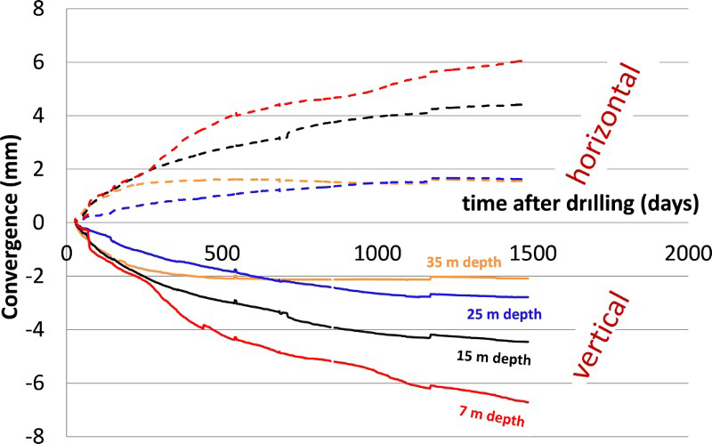
Modelling on long-term behaviour of the casing
The results of numerical simulations revealed that the casing was subjected to radial bending resulting in both, compressive and tensile circumferential stresses, with a maximum mechanical loading in the horizontal direction consistent with the results obtained from in situ experiment. They have also shown that early stage plasticity (from a few years to a few decades) can occur, promoting SCC on susceptible steel. Figure 6 shows an example of von Mises equivalent stress distribution in the casing. In this example, the yield strength is reached after 140 years. However, plastic deformations should remain localised and very low (less than 10−3 after 100 years, i.e. well below the ductile cracking thresholds of non-alloyed steels) so that they are not likely to affect the mechanical strength of the casing before a few hundred years assuming a mean corrosion rate of 10 μm/year considered as a maximum value in the long-term conditions for deep geological repository.
Von Mises stress in the casing 2 years (left) and 140 years (right) after construction of the disposal cell (2D simulations performed by Technological University of Troyes).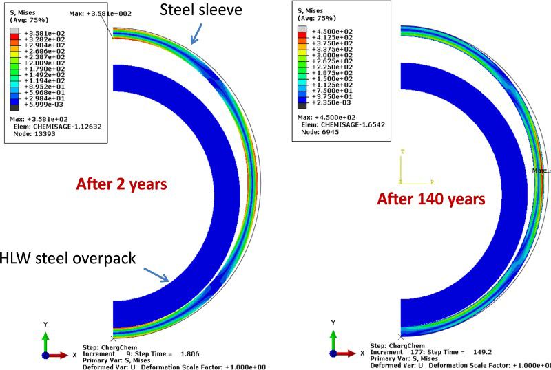
EAC assessment of the casing and overpack
The API 5L X65 grade (reference material for the casing in the French HLW concept) has a ferrite microstructure (see Figure 1) and a yield strength of 500 MPa (see Table 2), while the P285 NH grade (reference for the overpack in the French HLW concept) has a ferrite–pearlite microstructure and a yield strength of 300 MPa. For comparison, the P275 grade was investigated as it has a banded ferrite–pearlite microstructure that revealed susceptibility to EAC [3].
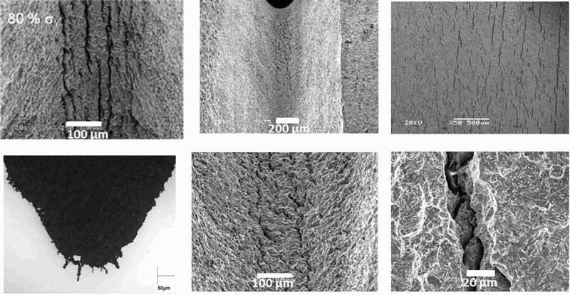
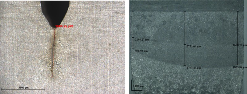
For crack initiation investigation, the samples were observed by using optical and scanning electron microscopy. In the notched area, observations on tensile specimens (all grades) revealed multiple micro-cracks after 8000 h of exposure (see Figure 7). Cross sections performed in the notch area showed cracks not exceeding a few tens of microns. Most of them were blunted, particularly inside notches for the specimens loaded to higher tensile stresses (110% σ y). This means that crack initiated but does not seem to propagate. Indeed, crack propagation investigations carried out on CT specimens (surface and cross sections) by using optical observations showed general corrosion and crack blunting (particularly for CT specimen loaded to 40 MPa OM observations of crack initiations for tensile specimen loaded to 80%σ y for 8000 h in COx claystone: API 5L X65: view of the notch (top left) and cross section of the notch area (bottom left); P285NH: view of the notch (top middle) and higher magnification of the notch area (bottom middle); P275: view of the smooth area in the useful part (top right) and higher magnification (bottom right). OM observations for crack propagation on CT specimen loaded to K = 15 MPa√m in pore-water COx claystone for 4000 h: API 5L X65 showing the fatigue precrack only (left) and P275 (after opening of the CT specimen) showing the fatigue precrack as well as crack propagation in depth after CT specimen opening (right). ) in clay deposit or pore-water. For the three investigated steel grades, very limited propagation (<150 µm) and particularly located near the CT flanks, was observed on the specimens exposed to clay deposit. Nevertheless, the P275 grade showed significant propagation in depth (after opening of the sample), when loaded to 15 MPa and exposed to pore-water for 4000 h (see Figure 8).
Micro-cracks also initiated on CT flanks, in the plastic zones near crack tips and more developed on the most loaded specimens clearly indicating the role of strain on their initiation.
Corrosion rate
The corrosion rates were calculated from weight loss measurements on coupons (all grades) exposed to pore-water or clay deposit for 4000 and 8000 h. The results revealed higher corrosion rate for the coupons exposed to the clay deposit than those exposed to pore-water. In addition, the results revealed a decrease of the corrosion rate overtime: in the range of 15-25 and 5-10 µm/year after 4000 and 8000 h of exposure in clay deposit and pore-water, respectively. Corrosion rates decreased over time as a consequence of the pseudo-passivation of the metal surface. Indeed the corrosion layers that gradually form tend to protect the metal surface, which then limits the exchange between the metal and the electrolyte [11]. Results from in situ experiments in clay environments confirm this trend as long as the pH remains neutral [12]. SEM observations revealed non uniform general corrosion for the API 5L X65 grade and preferential dissolution attack of the ferrite phase in contact with cementite (contained in pearlite or at the grain boundaries for the P275 and P285NH grades as shown in Figure 9. Further characterisations need to be conducted on the corrosion layers by using optical microscopy, scanning electron microscopy, Raman spectroscopy and X-ray diffraction.
SEM observation after exposure to COx claystone for 8000 h: API 5L X65 grade (left); P275 grade (right).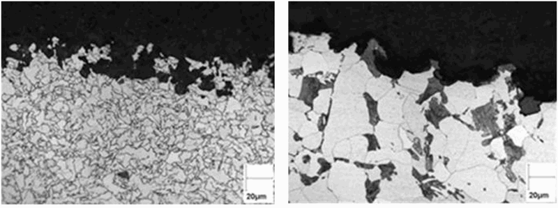
Conclusions
The in situ experimental results revealed significant anisotropic radial load of the casing which may result in local plastic strain under tensile stress, therefore leading to a potential risk of EAC.
Crack initiation investigation showed the formation of shallow and mostly blunted cracks on tensile specimens (all grades) loaded between 80 and 110% σ y.
Crack propagation investigation showed an absence of crack propagation in depth for API 5L X65 and P285NH steel grades but the presence of micro-cracks (up to 150 µm) in pore-water after 4000 h of exposure. They also confirmed the susceptibility to EAC for banded microstructure with a 2 mm crack propagation (P275 steel grade) in pore-water under K = 15MPa√m. Eventually they showed crack blunting for higher stress level, suggesting corrosion assisted by deformation. Crack velocity will be investigated to confirm crack arrest.
Non uniform general corrosion facies were observed on coupons (unloaded specimens) with preferential attack for steels with a ferrite–pearlite microstructure. Higher CR was measured in clay deposit with a tendency to decrease overtime in both media.
Footnotes
Acknowledgements
The authors wish to thank Khemais Saanouni and Carl Labergère from Technological University of Troyes for their helpful input and interesting discussion on modelling, as well as Olivier Gay and Pierre Teixeira from Egis Géotechnique for their contribution to in situ casing instrumentation.
Disclosure statement
No potential conflict of interest was reported by the authors.