
Abstract
A long-term in situ corrosion experiment is ongoing in the Mont Terri Underground Research Laboratory in Switzerland to (i) measure the in situ corrosion behaviour of carbon steel in compacted bentonite under simulated repository conditions, (ii) study the effect of the bentonite buffer density on microbial activity and microbially influenced corrosion and (iii) study the effect of welding on the corrosion rate. Carbon steel corrosion coupons, with and without welds, were surrounded by compacted bentonite with a range of dry densities and mounted in modules allowing free exchange with the local anoxic groundwater. After about 20 months of exposure, corrosion coupons and bentonite were sampled. A complex corrosion product was identified, consisting predominantly of magnetite. The bentonite adjacent to the metal was finer grained, more dispersed and enriched in iron. Aerobic, anaerobic and sulphate-reducing bacteria were identified both in the porewater surrounding the modules and in the bentonite.
This paper is part of a supplement on the 6th International Workshop on Long-Term Prediction of Corrosion Damage in Nuclear Waste Systems.
Introduction
Nagra (National Cooperative for the Disposal of Radioactive Waste, Switzerland) is considering using carbon steel as a potential canister material for the disposal of high-level waste and spent fuel in a deep geological repository in Opalinus Clay. Bentonite clay with a dry density of 1450 kg m−3 will be used to backfill the emplacement tunnels and will be placed around and between the disposal canisters. An in situ corrosion experiment is being conducted at the Mont Terri Underground Research Laboratory in Switzerland with the overall long-term objective of providing measurements of the corrosion rate of carbon steel in compacted bentonite under simulated repository conditions. The main goals are as follows:
Measure the in situ anaerobic corrosion rate of carbon steel in compacted bentonite under simulated repository conditions, and characterise the corrosion behaviour, in order to build confidence in canister lifetime predictions. Study the effect of the bentonite buffer on microbial activity and the microbially influenced corrosion of carbon steel. Study the effect of welding and post-weld heat treatment on the corrosion rate of carbon steel.
This paper describes the set-up of the experiments and summarises the results from a range of analyses that were carried out after 20 months of exposure.
Experimental
The experiment was installed in a vertical borehole in Opalinus Clay. Stainless steel modules, containing the carbon steel corrosion testpieces embedded in compacted bentonite with a range of controlled densities, were prepared under anoxic conditions and inserted into the borehole, which contained natural groundwater, and then sealed to maintain the long-term, low-temperature, anoxic conditions representative of those expected in a deep geological repository. The modules permitted the free exchange of water with the host rock. A set of 12 modules was initially installed in the borehole; they will be removed and analysed, and some will be replaced with fresh modules, according to a planned schedule over a 10-year period.
Bentonite preparation
Volclay MX80 bentonite from Wyoming, U.S.A. was used throughout the experiment. Four different conditions of bentonite were used, as follows:
1250 kg m−3, 1450 kg m−3 and 1550 kg m−3 compacted blocks: the compacted bentonite was provided by Clay Technology, Sweden. A 100 mm diameter mould that incorporated recesses for the corrosion coupons was manufactured. The bentonite was prepared to give a 95-99% degree of saturation using deionised water. It was placed in the mould, flushed with nitrogen and then placed under vacuum during compaction, in order to minimise the amount of residual oxygen present in the bentonite at the start of the experiment. The blocks of bentonite were then handled and stored in a nitrogen atmosphere until the modules were assembled. 1450 kg m−3, using a mixture of pellets and powder: this granular material was provided in the required density.
Preparation of corrosion coupons
Two sources of carbon steel test material were used to manufacture disc-shaped corrosion coupons with a diameter of 20 mm and a thickness of 10 mm:
A carbon steel cylinder with an electron-beam-welded lid was manufactured. The steel was ASTM A694-08 F65 (composition, wt-%: C 0.11; Mn 1.3; Si: 0.20; P 0.010; S 0.002; Cr: 0.10; Ni 0.07; Mo 0.17; V 0.053; Nb 0.037; Fe bal.). A reduced pressure electron-beam welding process was used (5 × 10⁻² mbar pressure, helium overpressure, accelerating voltage 150 kV, maximum beam current 255 mA, welding speed at full current 80 mm min−1) to perform a full penetration 14 cm deep weld, and a post-weld heat treatment (600°C for 4 h, then air-cooled) was applied before the material was used to prepare the test coupons. Each coupon was identified as weld metal (WM) or base metal (BM), together with its position in the weld and coupon number (e.g. WM1-1 or BM5-10). Electron-beam-welded 516 Gr 70 carbon steel (composition, wt-%: C 0.18; Mn 1.14; Si: 0.42; P 0.010; S < 0.005; Cr: 0.02; Ni 0.009; Mo 0.002; Nb 0.04; Fe bal.) rectangular bars contained BM, a 25 mm weld (‘shallow weld’) and a 50 mm weld (‘deep weld’). The coupons were numbered DW, SW and DWBM for deep weld, shallow weld and deep weld BM, respectively, followed by a location code (e.g. DW4A).
All coupons were grit blasted with grade 120/220 aluminium oxide powder to achieve a consistent surface roughness, R a, of ∼0.5 µm and ultrasonically cleaned in acetone. Before use, the coupons were weighed to an accuracy of 0.00001 g and photographed.
Assembly of corrosion test modules
The test modules were fabricated from stainless steel and were 250 mm long with an external diameter of 126 mm. The sintered stainless steel filters had an external diameter of 106 mm, a wall thickness of 3 mm, a porosity of 30% and an average pore size of 18 µm. The housings and filters for each module were cleaned in acetone and deionised water and then the modules were assembled in an argon-filled glove box (<0.1 ppm oxygen) to ensure that the starting conditions for the experiments were anoxic. Four layers of coupons, with three specimens in each layer, positioned at 120° intervals were installed in each module (Figure 1). The outer edge of the coupons was located 5 mm from the outer circumference of the bentonite.
Schematic cross-section through a test module showing the arrangement of corrosion coupons.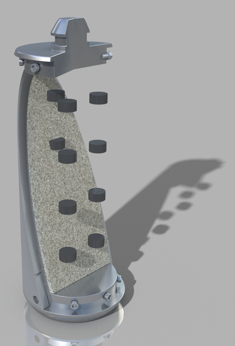
The modules were then pre-saturated with anoxic artificial Opalinus Clay groundwater by placing them in water-filled plastic containers for 2 days in the case of modules containing bentonite blocks, while the granular bentonite modules were soaked for 10 days. After soaking, the modules were heat-sealed into three layers of low permeability plastic (Mylar) bags to retain an anoxic argon atmosphere during transport.
Exposure
A 15 m deep vertical borehole was drilled in Opalinus Clay at the Mont Terri Underground Research Laboratory in St. Ursanne, Switzerland on 20 March 2012. After drilling, the borehole was flushed with argon four times, pressurised at 3.5 bar and sealed with a 2.5 m long hydraulic packer to maintain anoxic conditions. After sealing, there was an inflow of natural Opalinus Clay porewater at a rate of 44 mL day−1. The modules were installed in the Mont Terri facility on 10 January 2013. At that time, samples from the porewater that had accumulated in the borehole were taken for analysis and an additional 9 L of anoxic synthetic Opalinus Clay porewater were added in the borehole. During exposure, the in situ borehole temperature was ∼14°C.
Removal and analysis
Removal of test modules
Three of the test modules (Modules 1-3) were removed for analysis on 30 September 2014 after ∼20 months of exposure. During removal, porewater samples were taken from the borehole for microbial analyses. The modules were removed from the borehole while purging with argon and put into purpose-built stainless steel transfer flasks that were filled with water from the borehole and purged with argon before transport to the U.K. for analysis, where they were placed into a pre-cleaned and sterilised (wiped with a 70% isopropyl alcohol solution) argon-purged glove box for dismantling.
Analysis of corrosion coupons and bentonite
The specimens were analysed using a range of techniques that are summarised below.
Analysis of corrosion coupons
SEM examination and EDXA were carried out using a Hitachi TM3000 SEM equipped with a Bruker X-ray analysis system. Raman spectroscopy used a Horiba JY LabRam Aramis confocal Raman microscope, with an exciting laser wavelength of 532 nm. In order to determine the corrosion rate of the specimens, weight loss measurements were carried out in the glove box, according to a standard practice [1] and Clarke's solution (inhibited hydrochloric acid) was used as the descaling agent. The weight loss was converted to a corrosion rate given in units of µm/year.
Mineralogical and microchemical investigations of bentonite
Samples of bentonite were removed in an argon-purged glove box using a sharp stainless steel knife. For comparison, a ‘background’ reference sample of visually ‘unaltered’ compacted MX-80 bentonite, sampled distant from the corroded steel, was taken from the bentonite block used in Module 1. The methodology and approach used for the analyses were similar to those used previously to study samples from iron–bentonite interaction experiments [2,3].
Polished thin sections were prepared from sub-samples of both background MX-80 bentonite and reacted bentonite near the corroded steel coupon. Low magnification images of whole thin sections were recorded by digitally scanning the thin section using an Epson Perfection 1240U flatbed scanner equipped with a transmitted light (transparency) scanning attachment. The polished blocks and sections were then initially examined using a Zeiss Axioplan 2 optical petrographic (polarising) microscope, before being examined in detail using BSEM. Element distributions in the bentonite matrix surrounding corroded steel coupons were studied using EDXA and energy-dispersive electron probe microanalysis (EPMA).
Intact vacuum-dried fragments of the material, measuring approximately 20 × 10 mm, were impregnated with epoxy-resin under vacuum in order to stabilise the material for polished section preparation. They were then cut and polished under propanol (to prevent reaction of the smectite with water-based cutting fluids). The sections were finished by polishing with a 0.45 µm diamond paste.
BSEM-EDXA and EDXA-EPMA analyses were carried out using a FEI Company QUANTA 600 environmental SEM in conjunction with INCA Microanalysis software. The polished thin sections were coated with a thin (25 nm) layer of carbon by carbon evaporation under vacuum. X-ray elemental maps were processed to show relative element concentrations using a ‘rainbow colour scale’ (blue for none to red/white for high).
X-ray diffraction analysis of bentonite
In order to study the bulk mineralogy of the samples and to prevent further oxidation of any Fe-bearing species, small (typically ∼10 mg) portions of material were rapidly removed using a scalpel and ground to a fine powder. The powder was then deposited onto the surface of ‘zero-background’ silicon crystal substrate X-ray diffraction (XRD) mounts using a single drop of acetone to form a deposit with random crystal orientation. Such analyses were carried out to determine the nature of any non-clay minerals present in the samples and also to determine the d 060 spacing of any clay minerals present. Subsequently, the clay mineral assemblages of the samples were studied by preparing oriented mounts. This involved dispersing small (typically ∼10 mg) portions of material in deionised water using ultrasound treatment and no dispersant was added. The dispersions were then pipetted onto glass slip substrates and allowed to dry at room temperature.
XRD analysis was carried out using a PANalytical X'Pert Pro series diffractometer equipped with a cobalt-target tube, X'Celerator detector and operated at 45 kV and 40 mA. The random powder mounts were scanned from 4.5 to 85° 2θ at 2.06° 2θ min−1. Diffraction data were initially analysed using the PANalytical X'Pert HighScore Plus version 4.1 software coupled to the latest version of the International Centre for Diffraction Data (ICDD) database. The basal XRD spacings of smectite-group minerals are particularly susceptible to the prevailing humidity and temperature conditions when analysed. Therefore, in order to ensure constant conditions, air-dried oriented glass slip mounts were placed in an Anton Parr THC (controlled temperature and humidity) chamber attached to the diffractometer system and operated at 50% relative humidity and 40°C. Samples were conditioned at these settings for 30 min before scanning from 2-35° 2θ at 0.55° 2θ min−1. The mounts were then rescanned after glycol-solvation and after heating to 550°C for 2 h with the chamber set to 40°C and ambient humidity. In order to gain further information about the nature of the clay minerals present in the sample, modelling of the <2 µm glycol-solvated XRD profiles was carried out using Newmod II™ software [4].
Porewater and microbial analyses
The bentonite was cut and sampled with sterile knives and spatulas and packed in sterile sampling bags, then packed in two layers of Mylar bags under argon and kept at 4°C. In order to see any variation in the distribution of microbial activity in the bentonite and around the corrosion coupons, samples were taken at various locations. A single sample from each module was used for the measurement of water activity.
Microbial enumeration was performed by preparing a suspension from the small pieces of sample section destined for cell culturing by adding a weighed amount of sample to a known volume of phosphate-buffered saline solution (PBS, i.e. 0.01M NaCl buffered to pH 7.6 with 9 mM Na2HPO4 and 1 mM NaH2PO4·H2O), which was then stirred for 30 min to 1 h. Serial dilutions (100 to 10−3 in PBS) of the suspensions were used in the enumerations.
Aerobic heterotrophs were enumerated on R2A medium [5]. Aerobic plates were poured in a laminar flow hood and incubated at 30°C for 3-3.5 days. Anaerobic heterotrophs were also cultured on R2A medium in an anoxic glove box and incubated at 30°C under anoxic conditions for 17-28 days. Sulphate-reducing bacteria (SRB) were enumerated by the most-probable number (MPN) method in modified Postgate's B medium [6] and incubated at 30°C under anoxic conditions for 35-71 days.
The sampled porewater was filtered on site for DNA analysis, using a sterile filtration device equipped with 0.2 μm polycarbonate membranes (Millipore Corporation, Billerica, U.S.A.). Four filtrations of 250 mL each were performed. DNA was extracted from filtered water samples using a slightly modified protocol from the DNA Spin kit for Soil (MP Biomedicals, Illkirch, France) and then purified using the Genomic DNA Clean & Concentrator purification kit (Zymo Research, Freiburg, Germany). The total amount of DNA extracted was 19.5 ng and the final suspension had a concentration of 0.195 ng μL−1. The relatively low amount of DNA recovered can be attributed to a low microbial activity in the borehole and/or the presence of clay particles that could have decreased the DNA extraction yield. The DNA collected from the borehole sample was amplified with universal bacterial 16S rRNA primers (28f 5′-GAG TTT GAT CNT GGC TCA G-3′ and 519r 5′GTN TTA CNG CGG CKG CTG-3′), using 35 cycles with an annealing temperature of 50°C. The PCR products were purified with MSB® Spin PCRapace (TRATEC Biomedical AG, Birkenfeld, Germany) before sequencing at the Research and Testing Laboratory in Lubbock (U.S.A.). After sequencing was performed, data analysis was carried out using QIIME.
The filtrate was used for chemical analysis. Hydrogen sulphide, iron(II) and iron(III) were analysed within 24 h after the sampling, using a UV-2501PC spectrophotometer (Shimadzu, Duisburg, Germany). Hydrogen sulphide (H2S, HS− and S2–) was measured using the Cline method, and Fe2+ and Fe3+ with the ferrozine assay. The filtered borehole porewater was analysed for the following:
pH using a Orion 3-Stars pH meter (Thermo Scientific, Waltham, MA, U.S.A.). Major anions and cations by ion chromatography, using an ICS-3000 instrument (Dionex, Sunnyvale, CA, U.S.A.). For anions, 30 mM KOH was used as the eluent, with an IonPac AS11-HC column. The cations were measured with 40 mM of methanesulphonic acid as the eluent, with an IonPac CS16 column. Trace metals: Fe, Mn, Cr, Cu, Co, Ni, Zn, Sr, Si and Al were analysed using inductively coupled plasma mass spectrometry on an Elan DRC II instrument (Perkin Elmer, Waltham, MA, U.S.A.).
Results
Weight loss measurements
The results of the weight loss measurements are summarised in Figure 2. On the basis of the weight loss measurements, it can be seen that the corrosion rate increased in the following order: Module 3, compacted block, 1550 kg m−3 < Module 2, compacted block, 1250 kg m−3 < Module 1, pellets, 1450 kg m−3.
Average corrosion rates based on weight loss measurements for the tested materials and bentonite densities.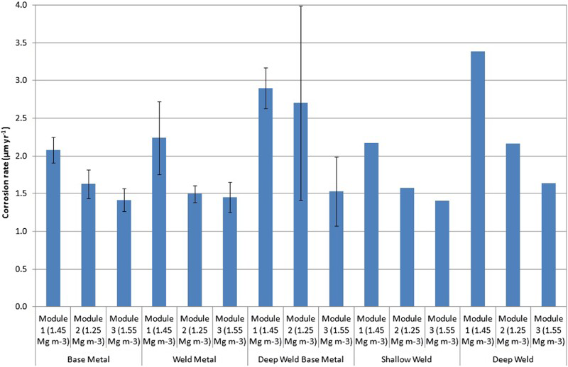
SEM and EDXA analysis
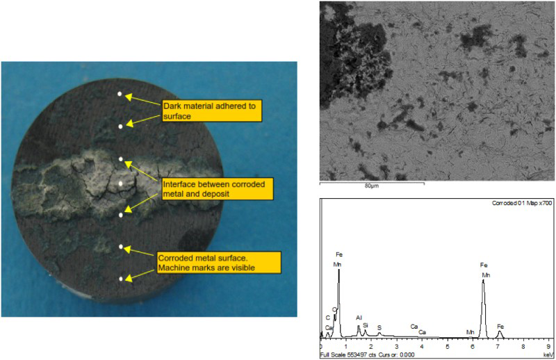
SEM examination was carried out on specimens in the ‘as removed’ condition from the experiments (e.g. coupon SW4A in Figure 3). The surface of the sample is complex, consisting of a brightly coloured deposit, which is most probably bentonite, an adherent dark material, and exposed corroded metal. A number of observations can be made from the SEM/EDXA, as follows:
There appears to be no significant difference in the surface composition for the same materials in different modules. The corroded areas exhibited significantly more complex compositions than the less corroded areas. The interface areas exhibited high impurity levels (Si, Ca, Mg, Na) for some specimens, indicating the presence of residual bentonite. The composition for the dark material is complex and shows high Al, Ca and S concentrations. The distribution of S (and Cl but to a lesser extent) usually appears identical to that of Fe. The detection of silicon and aluminium is indicative of the presence of residual bentonite on the coupon surface, or incorporated into the corrosion product. Photograph identifying different areas of the surface of specimen SW4A (Module 1, 1450 kg m−3), which were analysed with SEM and EDXA, as shown in the example on the right hand side (a representative area of corroded metal surface).
Raman spectroscopy
Raman spectroscopy analysis was performed on a number of specimens from Modules 1 and 2, and spectra were obtained from different regions on each specimen. The main peak for all areas on specimen DW4A (Module 1, Figure 4) is centred at ∼650 cm−1, which is most probably due to the presence of magnetite. A shift in the position of the peak compared to the standard may indicate that the corrosion product was sub-stoichiometric. This peak is larger for the dark material and illustrates the transfer of magnetite from the specimen to the bentonite. Very little magnetite was seen at the specimen/bentonite interface. Peaks at ∼210 and 270-320 cm−1 may be indicative of the presence of haematite.
Raman spectra for DW4A (Module 1, 1450 kg m−3).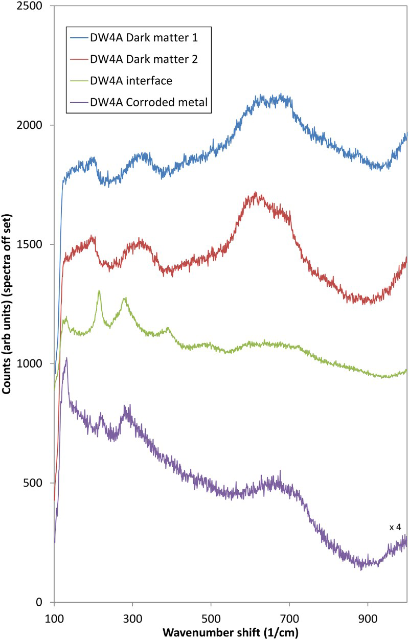
Spectra from other specimens confirmed the presence of magnetite and haematite corrosion products. Several sharp bands were identified at lower wavenumbers and these can be attributed to an oxyhydroxide phase. In some cases, the spectra obtained from the dark material were dominated by fluorescence from the bentonite, suggesting that the dark material forms the interface between corroded metal and bentonite and consists of a mixture of the two materials.
Petrographical observations
This section describes the results obtained for sample BM2-4 (Module 1), but samples from other modules showed very similar results. The reacted bentonite immediately adjacent to the reacted carbon steel coupon was heavily stained to a strong reddish-brown to ochreous colour, but the steel surface was shiny and blackened. In thin section, the brown ochreous staining surrounding the steel was seen to penetrate the bentonite matrix up to a sharply defined depth of ∼2 mm from the interface with the steel (Figure 5). The alteration halo is visually similar to that observed in bentonite adjacent to corroded steel wires in previous experiments [2,3].
Transmitted light image of thin section (blue-dye epoxy-resin impregnated sample) through the bentonite/carbon steel interface (BM2-4 coupon removed, Module 1, 1450 kg m−3).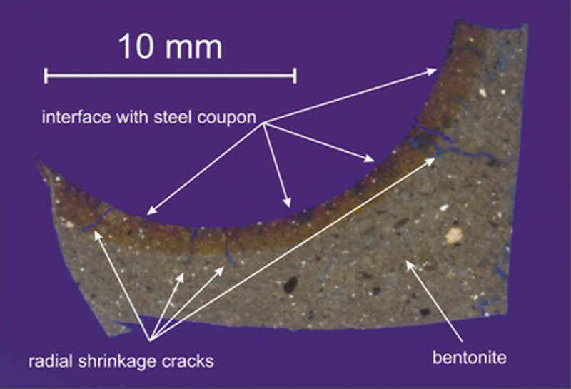
A series of small radial microfractures was observed to have developed perpendicular to the bentonite/steel interface. High-resolution BSEM imaging also showed the development of discontinuous hairline microfractures parallel to the bentonite/steel interface that link with the radial microfractures to form an anastomosing network (Figure 6). BSEM-EDXA observations found no evidence for any secondary iron oxide corrosion products or other alteration products within these microfractures. Although the radial microfractures extended up to 4 mm into the bentonite, most of the microfractures were confined within the brown iron-stained alteration zone.
BSEM photomicrograph of the bentonite/steel contact (BM2-4 coupon removed from top left corner, Module 1, 1450 kg m−3).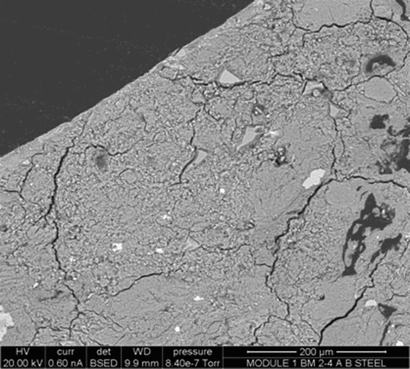
BSEM-EDXA shows that the fabric of the bentonite immediately adjacent to the steel was altered within a zone 10-20 µm wide (Figure 7), within which the bentonite fabric was finer-grained and more dispersed or diffuse, with individual clay particles more difficult to differentiate under BSEM. In contrast, the matrix of the bentonite further away from the steel/bentonite interface was coarser, with discrete bentonite aggregate particles clearly visible. Furthermore, the altered zone displayed patches of bentonite that were enriched with iron, as shown by the brighter backscattered electron coefficient. Iron enrichment was also seen along the interface between the steel and the bentonite. EDXA microchemical analysis and element distribution mapping of the bentonite/steel interface are shown in Figure 8. Mapping of the iron distribution confirms that the bentonite matrix is enriched at the contact with the steel. The iron concentration is particularly high at the contact surface and decreases gradationally with distance but extends for at least 100 µm into the matrix. Although the brown iron staining of the bentonite can be seen visually to penetrate up to ∼2 mm into the bentonite (Figure 5), EDXA could not detect an enhanced concentration of iron beyond about 100 µm.
(a) BSEM photomicrograph of the section through the bentonite at the interface with the steel coupon (BM2-4 coupon has been removed from top left corner, Module 1, 1450 kg m−3) (b) detail of inset area in (a). BSEM photomicrograph of the steel/bentonite interface (Module 1, 1450 kg m−3: BM2-4), and corresponding EDXA microchemical maps of the same area for iron, silicon, aluminium, calcium and sulphur. Colour concentration scale: red = high concentration, blue/black = low concentration.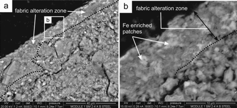
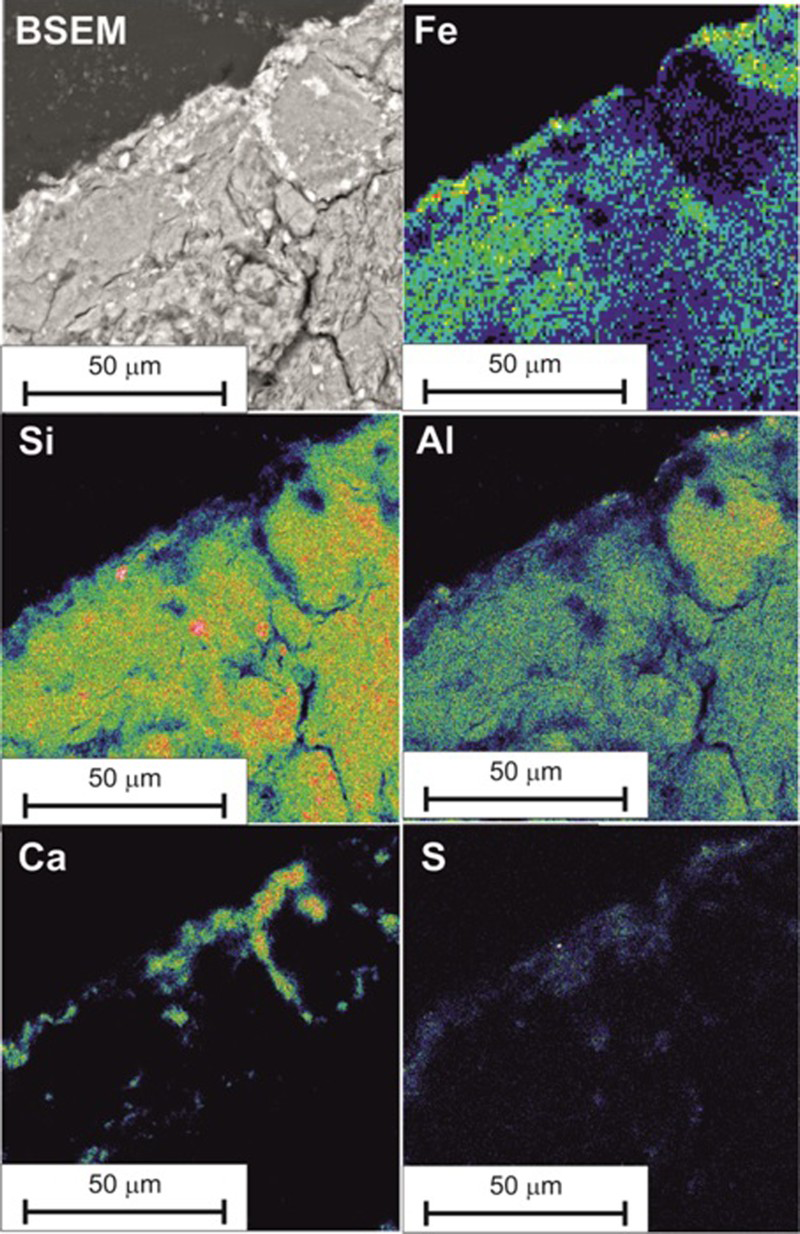
Calcium and sulphur were also found to be enriched in the bentonite in a zone about 10-20 µm wide, immediately adjacent to the contact with the steel. The calcium and sulphur are closely associated and correspond to the presence of a discrete phase seen under BSEM that appears bright relative to the smectite clay matrix. This is, therefore, interpreted to most probably be calcium sulphate (either gypsum (CaSO4·2H2O) or anhydrite (CaSO4)). The calcium sulphate was also found to fill microfractures up to 10 µm wide penetrating into the bentonite from the interface or fill aggregate grain boundary cracks around component bentonite aggregate particles. Silicon and aluminium appear to be reduced at the steel/bentonite interface (Figure 8).
X-ray diffraction analysis
Summary of random orientation mount XRD analyses for samples taken from adjacent to the steel coupon.
Summary of oriented mount XRD analyses.
Key: Glycol 002/003 = XRD d 002/d 003 peak intensity ratio from glycol-solvated trace, for samples taken from adjacent to the steel coupon.
‘Unaltered’ bentonite
Powder XRD analyses indicate that the ‘unaltered’ grey bentonite, both distant from and close to the coupon alteration zone, was predominantly composed of montmorillonite. The montmorillonite in these regions displays an intense d 001 peak with a mean spacing of 12.64 Å (range of 12.46-12.78 Å). The montmorillonite d 00l intensities can also be used to gain information on Fe substitution by measuring the scattering from the clay mineral octahedral sheet (Table 2). The intensity ratio of the d 002 to the d 003 peaks increases, as the total number of electrons in the octahedral sheet increases. Newmod II-modelled profiles were produced for the increasing Fe content categories: montmorillonite senso stricto, non-ideal montmorillonite, Fe-rich montmorillonite and nontronite identified by Newman and Brown [7] and their d 002/d 003 was measured. Newmod II-modelling and a mean, measured d 002/d 003 value of 0.60 for the ‘unaltered’ bentonite subsample suggest a montmorillonite senso stricto composition (∼0.27 Fe3+ per O20(OH)4). Peak width measurements coupled with Newmod II-modelling suggest a mean defect-free distance of 9 layers (12.5 Å units) and a size range between 1 and 14 layers. A mean measured d 002/d 003 value of 0.62 for the ‘unaltered’ bentonite closer to the altered zone suggests a montmorillonite senso stricto composition (∼0.30 Fe3+ per O20(OH)4), which is slightly more ferroan than the more distal ‘unaltered’ bentonite.
Corroded steel coupon-altered bentonite zone
XRD analyses of the stained bentonite in contact with the corroded steel coupons indicate that it had a generally similar mineralogy to the ‘unaltered’ bentonite. The montmorillonite in the coupon-altered bentonite subsamples displayed a mean d 001 peak spacing of 12.70 Å. The d 002/d 003 values for the ‘altered’ bentonite subsamples range from 0.25 for Module 1 to 0.32 for Module 2 and 0.74 for Module 3. These values, together with Newmod II-modelling, suggest a montmorillonite senso stricto composition for all three samples but a more ferruginous composition (∼0.46 Fe3+ per O20(OH)4) for the Module 3 sample.
Porewater and microbial analyses
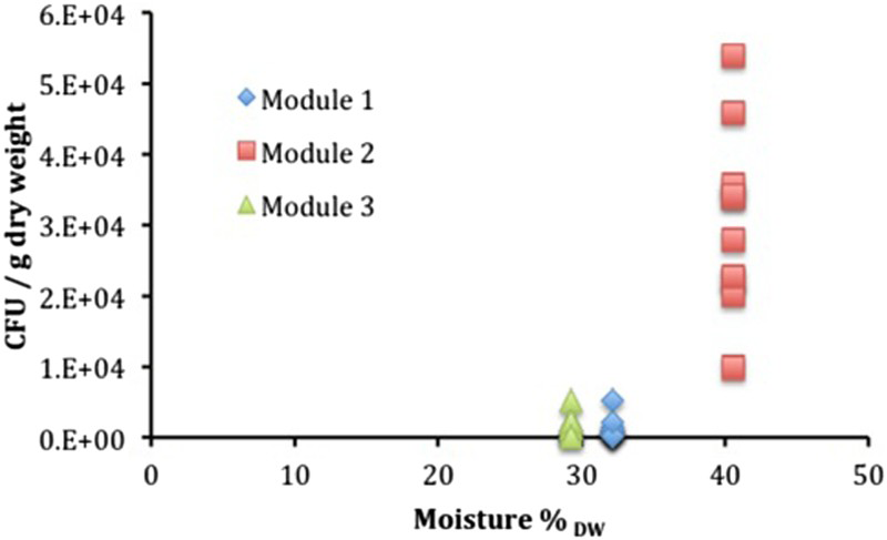
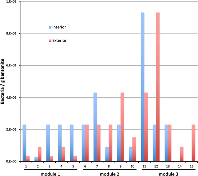
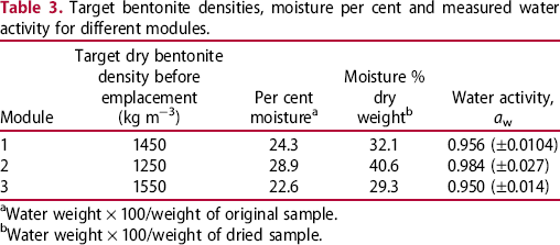
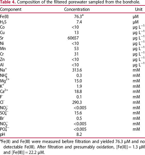
The results of the measurements of water activity are included in Table 3 and a summary of the results of the microbial analysis is presented in Figure 9 for anaerobic heterotrophic microorganisms, Figure 10 for aerobic heterotrophic microorganisms and Figure 11 for SRB. The results of the chemical analysis of the porewater sampled from the borehole are given in Table 4. These results clearly show that this borehole was maintained under anoxic conditions, as substantial concentrations of reduced Fe and S were found.
Summary of cultivation results for anaerobic heterotrophic microorganisms plotted as a function of measured moisture content (as % of dry weight). Summary of cultivation results for aerobic heterotrophic microorganisms plotted as a function of measured moisture content (as % of dry weight). Summary of cultivation results for SRB. Target bentonite densities, moisture per cent and measured water activity for different modules. aWater weight × 100/weight of original sample. bWater weight × 100/weight of dried sample. Composition of the filtered porewater sampled from the borehole. aFe(II) and Fe(III) were measured before filtration and yielded 76.3 μM and no detectable Fe(III). After filtration and presumably oxidation, [Fe(II)] = 1.3 μM and [Fe(III)] = 22.2 μM.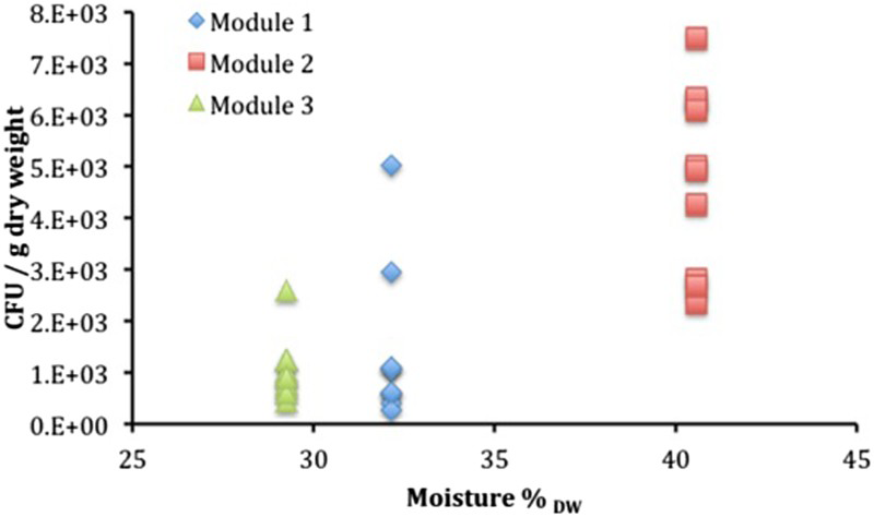
The analyses of the porewater sample taken before exposure showed that the great majority of the contributing genera (86%) fall within the Peptococcaceae family. Two genera dominate the community: Desulfurispora sp. and Desulfosporosinus sp. The only reported member of the genus Desulfurispora is D. thermophile. This microorganism is able to reduce sulphate, sulphite, thiosulphate and elemental sulphur as the terminal electron acceptor and to use H2/CO2 (80:20, v/v), alcohols, various carboxylic acids and some sugars as electron donors. It represents 70% of the retrieved sequences in this sample, while it is not detected in any other sampled boreholes within the Mont Terri facility. The second microorganism, related to Desulfosporosinus meridiei, is also likely to be a sulphate-reducing bacterium. It can use sulphate, sulphite, thiosulphate, elemental sulphur, DMSO and Fe(III) as electron acceptors in the presence of lactate. In addition, it can use H2/CO2, acetate, pyruvate and a number of organic acids as electron donors. A detailed analysis of the microbial ecosystem in the test borehole has been reported elsewhere [8].
The analysis of the porewater sample taken after exposure showed a significant change in the microbial community with a large increase in the number of Pseudomonas (87%).
Discussion
Corrosion rates
The analyses of the corrosion coupons have demonstrated that surface damage of the carbon steel had developed due to corrosion in the bentonite over a period of 1.72 years. The corrosion rates have been derived from weight loss measurements and range from 1.21 to 3.38 µm/year. It is apparent that both bentonite density and the initial form of the bentonite have a significant influence on the rate of corrosion, across all materials. The corrosion rates for all specimens in the module with the greatest block density (Module 3, 1550 kg m−3) were lower than those in the other modules with lower bentonite density. The influence of the initial bentonite form can also be seen, as the corrosion rate was lower for all specimens in the modules containing compacted bentonite blocks compared to the specimens in the module containing pelletised bentonite. This is despite the fact that the bentonite density of one of the modules containing block bentonite (Module 2, 1250 kg m−3) was lower than that of the module containing pelletised bentonite (Module 1, 1450 kg m−3). In contrast to the bentonite density, the effects of the steel composition and the presence or absence of welds on the corrosion rate are minor.
Composition and morphology of corrosion product
Raman spectroscopy analysis of the specimens indicates that the corrosion product was predominantly sub-stoichiometric magnetite or a mixed phase spinel (e.g. Fe3−x M x O4) and also that some haematite may have been present, which may have been a residue from the pre-test surface preparation.
SEM analysis shows a complex corrosion product that differed slightly between materials and also across the surface of the materials, while the presence of aluminium and silicon on a number of specimens indicates the presence of bentonite remaining on the specimens.
Analysis of bentonite–steel interaction
XRD analysis
XRD analysis revealed that the ‘unaltered’, grey bentonite both close to and distant from the coupon alteration had a similar composition to that previously described for MX-80 [9]. The oriented XRD mount data, obtained under 40°C and 50%RH conditions, generally indicate a relatively consistent ∼12.7 Å spacing of the montmorillonite air-dry d 001 with a subordinate shoulder peak at ∼14.6 Å in both the ‘unaltered’ and ‘altered’ bentonite samples. Exceptionally, the air-dry d 001 spacings are reversed in the Module 1 sample where the most intense air-dry d 001 is at ∼14.8 Å with a shoulder at ∼12.7 Å (Table 2). As these oriented mounts were analysed under constant humidity and temperature conditions, the difference in d 001 spacings must be the result of a change in cation chemistry in the montmorillonite. The ∼12.7 Å spacing suggests that the predominant interlayer cation is monovalent (Na/K), while the ∼14.6 Å spacing suggests divalent (Ca/Mg) cations. The reason that the XRD observations should indicate a preponderance of divalent cations in Module 1 is unclear. In the samples from Module 2 and Module 3, the ‘altered’ bentonite samples show a mean, air-dry d 001 spacing of 12.68 Å with a mean, shoulder spacing of 14.72 Å, suggesting the reverse situation where monovalent (Na/K) cations predominate over divalent (Ca/Mg) cations. The mineralogical alteration revealed by detailed petrographic analysis of Module 1 suggests that it is broadly similar to that observed in Module 2 and Module 3, although no calcium mineralisation was observed in the latter.
The mean d 002/d 003 value for the montmorillonite in the ‘unaltered’ bentonite ‘A’ and ‘C’ subsamples (see Table 2 for definition of position of subsamples) of 0.61 (∼0.30 Fe3+ per O20(OH)4) compares to values of 0.25 (Module 1), 0.32 (Module 2) and 0.74 (Module 3) obtained for the ‘altered’ bentonite ‘B’ subsamples. Newmod II-modelling suggests that the montmorillonite in the coupon-altered subsamples from Module 1 and Module 2 had a Fe-depleted composition (∼0 Fe3+ per O20(OH)4) compared to that found in the ‘unaltered’ samples. Conversely, the d 002/d 003 values and Newmod II-modelling indicates a more Fe-rich composition (∼0.46 Fe3+ per O20(OH)4) for the montmorillonite in the coupon-altered subsample from Module 3. Such an increase may suggest an increase in the total number of electrons in the octahedral sheet of the ‘altered’ bentonite, possibly as a result of Fe substitution. This might indicate that Fe2+ or Fe3+ from the corroding steel had displaced interlayer cations in the smectite, and this had subsequently converted to form an Fe-rich octahedral layer. This would have the overall effect of increasing the apparent Fe-substitution within the octahedral layer of the bulk of the smectite, and might provide an alternative explanation for the increase in d 002/d 003 values for the montmorillonite component in the ‘altered’ bentonite in this experiment.
Petrographic and microchemical observations
The bentonite in Module 1 (1450 kg m−3) and Module 3 (1550 kg m−3) showed significant alteration of the clay fabric immediately adjacent to the corroding steel. This altered fabric layer was not obvious in Module 2 (1250 kg m−3), suggesting that there may be an effect of density on the characteristics of the altered layer.
The ‘iron-stained’ region of the bentonite appeared to display a subtly different behaviour to the background bentonite further away from the steel. The altered layer typically displayed the ready development of shrinkage cracks that were orientated radially and concentrically to the bentonite/steel interface. Most of these microfractures were unmineralised by secondary reaction products and they are considered to result from drying of the bentonite during thin section preparation. However, these shrinkage cracks were less obvious in the unaltered bentonite, which suggests that the iron-stained altered bentonite may have subtly different shrinkage and/or swelling properties compared to that of the original bentonite.
In some samples, some microfractures were observed to display walls enriched by iron. This suggests that some of these features are not artefacts of sample preparation and may actually have formed during corrosion of the steel, providing pathways along which the iron migrated away from the corroding steel. Much of the iron staining and iron enrichment also delineates the original boundaries of the bentonite aggregate pathways, which suggests these particle boundaries provided preferential pathways for pore fluid migration, potentially also including hydrogen, through bentonite.
Calcium showed a marked enrichment in the bentonite matrix immediately adjacent to the corroding steel in Module 1 and Module 2. In the case of Module 1, the calcium enrichment was closely associated with an increased concentration of sulphur, which suggests that calcium sulphate (possibly gypsum or anhydrite) had probably precipitated. The presence of calcite and gypsum was confirmed by the XRD analysis. In Module 2, the calcium concentration is associated with the precipitation of rhombohedral microcrystals of calcite. These observations closely resemble those found in previous experiments [2,3], which indicated that subordinate Ca2+ ions in the exchangeable cation sites of smectite in the MX-80 bentonite migrate towards the corroding steel surface, leading to the precipitation of calcite and aragonite adjacent to the corroding metal surface. It seems likely that the concentration of calcium observed around the corroding steel coupons in the present experiment represents the early stages of a similar process. Module 3 appeared to be different to the other two modules. No enrichment of calcium or sulphur was observed in the bentonite adjacent to the corroding steel in this experiment and no evidence was found for either calcite or calcium sulphate precipitation.
Comparison with laboratory corrosion experiments
The results from the in situ Mont Terri experiment can be compared to those from a concurrent laboratory programme to measure the long-term corrosion rate of carbon steel [10], by measuring the rate of gas evolution. It should be noted that the environmental conditions for the Mont Terri specimens differ significantly from those used in the laboratory experiments, particularly with regard to the temperature of the Mont Terri experiment which is approximately 15°C compared to 60°C for the laboratory experiments, as well as the presence of a microbial population characteristic of a water-filled borehole in Opalinus Clay rock.
Corrosion rates derived from the monitoring of hydrogen evolution in the laboratory, assuming the formation of Fe(OH)2 and Fe3O4 over durations similar to those of the Mont Terri experiment, were similar. The corrosion rate of laboratory-based experiments in bentonite saturated with synthetic Opalinus Clay porewater over a comparable exposure period ranges from 2.65 to 3.92 µm/year, which is slightly higher than the values measured in situ (1.21-3.38 µm/year). Such corrosion rates are in general agreement with rates reported in the literature for similar exposure conditions and durations [11].
Comparison of the Raman analysis carried out on specimens from the laboratory experiments and the in situ experiments shows that the corrosion product formed in the Mont Terri experiments was very similar to that produced in the laboratory experiments.
Microbial analysis
The analyses of the porewater indicate that the conditions in this borehole (anoxic, reducing) are favourable for the growth of sulphate-reducing bacteria. The increase in the contribution of Pseudomonas to the community during the exposure period is largely accounted for by the decrease in a member of the Peptococcaceae family, which pertain to the genus Desulfotomaculum. Based on the original metagenomic study, it was determined that this organism was capable of heterotrophic sulphate reduction, probably using organic matter from the breakdown of microbial necromass as well as using H2 as an electron donor [8]. The Pseudomonas species was thought to use hydrolysed organic matter from the Opalinus Clay. Its emergence as the dominant organism suggests that the availability of H2 may have decreased and organisms dependent on that electron donor (such as Desulfotomaculum spp.) may have given way to organisms presumed to utilise the refractory organic matter in Opalinus Clay (such as Pseudomonas sp.).
When comparing the number of anaerobic heterotrophs (i.e. bacteria that use organic compounds as a source of carbon and that grow in the absence of oxygen) among the bentonite samples from the three modules, it appears that, as expected, Module 2, which had the lowest target dry density, exhibited the highest numbers of anaerobic heterotrophs. Modules 1 and 3, in contrast, both showed lower numbers. There is more variability in the anaerobic heterotroph numbers in Module 1, with the next lowest density after Module 2, than in Module 3. This suggests that the density of 1450 kg m−3 represents a near threshold for MX80 bentonite inhibition of microbial activity. The threshold is probably in the range between 1250 and 1450 kg m−3. This is in contrast to other reports for other bentonites, where varying Febex bentonite densities in the range of 1260-1620 kg m−3 resulted in very limited impact on the numbers of heterotrophic anaerobic bacteria and the threshold of aerobic bacteria was found [12] to be around 1500 kg m−3.
Aerobic heterotrophic bacteria, which use oxygen as an electron acceptor, exhibit a similar behaviour as the anaerobes, with the difference that cell counts were typically greater for the former. There is also less variability in the cell numbers among samples from Module 1, in comparison with anaerobic heterotrophs. This is probably due to the heterogeneity of the module and to the fact that individual samples were distinct for anaerobic and aerobic enumeration. While Module 2 exhibited the largest aerobic heterotroph cell counts, Modules 1 and 3 revealed cell counts within an order of magnitude of each other, with Module 3 showing the larger counts. However, given the limited dynamic range of this type of analysis, it is difficult to draw conclusions from this result.
The sampling was carried out in such a way as to allow evaluation of the impact of location of individual samples on cell counts. There was no clear systematic trend observed from the data, but it appeared that the exterior location typically supported higher cell numbers than the interior location for plate counts. The lack of a clear trend suggests that microorganisms present in the bentonite rather than microorganisms entering from the borehole were present and viable in the modules, despite the fact that the filter pore size was large enough (18 μm) to allow entry of microorganisms.
SRB numbers were evaluated by the MPN method. The SRB counts were generally higher in the interior than the exterior of each subsample, particularly for Module 1. There was no specific trend as a function of location in the subsample for the other two modules, suggesting that the SRB originated from the bentonite rather than the porewater. Surprisingly, the number of SRB was slightly higher in Module 3 (the module with the highest dry density, 1550 kg m−3) than in the other two modules. The most likely explanation for this behaviour is the presence of spore-forming SRB and their uneven distribution in the bentonite. The SRB numbers were generally higher than those obtained for Febex [12].
The analyses conducted here provide only information about the viability of microorganisms in bentonite. The finding, which is in line with previous work [13], shows that viable microorganisms are present in bentonite and, depending on the density of the clay in the module, a fraction of those microorganisms remain viable. As expected, at higher densities, a smaller fraction survives, while at lower densities, a higher fraction survives. However, it remains unknown whether microbial activity is extant in the bentonite. The only evidence of this activity was presented in the Engineered Barrier experiment [12]. The question of whether a specific bentonite density might preclude microbial survival has been investigated by several groups and the results do not provide a clear density threshold. For Febex [12], the threshold is around 1600 kg m−3, whereas for MX-80 [12], the threshold appears to be closer to 1500 kg m−3. It would appear from this work that the threshold for MX80 may be between 1250 and 1450 kg m−3.
Conclusions
An in situ corrosion experiment has been set up and operated in the Mont Terri Underground Research Laboratory and three modules have been removed for detailed analysis after ∼20 months of exposure. The main conclusions from this analysis are as follows:
Greater bentonite density (for the same bentonite form) significantly reduced the extent of corrosion for all materials. The corrosion rate of all materials is lower where blocks of compacted bentonite are used in comparison to pellet bentonite, even if the dry density of the block bentonite is lower than the pellet bentonite. There was little difference in corrosion rate between the WM and BM samples for both steel types, for the same bentonite density. A complex corrosion product, which is predominantly magnetite, has been identified. A narrow region of discoloured bentonite up to 2 mm wide exists around the surface of the steel, which probably has subtly different physical properties to the bulk material but contained no evidence for any secondary iron oxide corrosion products or other alteration products. Increased Fe content was identified only within 100 µm of the steel surface. Within a ∼20 µm narrow alteration zone next to the metal, the bentonite was finer-grained and more dispersed. The corrosion rates observed in this work are similar to those seen for tests carried out ex situ at higher temperatures, while the corrosion product observed in both experiments was also similar. The bentonite with the lowest density exhibited the highest numbers of anaerobic and aerobic heterotrophs, while SRB were most active on the interior of the bentonite, suggesting that the SRB originated from the bentonite rather than the porewater. It would appear from this work that the threshold density for microbial activity in MX80 may be between 1250 and 1450 kg m−3.
Footnotes
Acknowledgements
The authors gratefully acknowledge Oxford University Materials Characterisation Service for providing analytical data, TWI (The Welding Institute, UK), for provision of welded carbon steel material, Clay Technology (Sweden), for providing the compacted bentonite samples, the Swisstopo team and Solexperts (Switzerland) for on-site work at the Mont Terri Rock Laboratory, Special Techniques (UK), for manufacture of the transfer flasks, Drs Anthony Milodowski and Simon Kemp (BGS, UK), for the mineralogical analysis of the bentonite, and Atomic Energy of Canada Limited (Canada) for measurements of water activity.
Disclosure statement
No potential conflict of interest was reported by the authors.