
Abstract
The formation of copper sulphide films on copper in aqueous sulphide solutions has been investigated under both natural corrosion and electrochemical conditions. Film growth occurs at the Cu2S/electrolyte interface and involves Cu+ transport through a generally porous film. Both corrosion and anodic film growth are suppressed by high chloride concentrations. Passivity, a pre-requisite for pitting, is achievable only at high sulphide concentrations and transport fluxes, conditions not expected under most geologic repository conditions since both sulphide groundwater concentrations and diffusive transport rates are expected to be low.
This paper is part of a supplement on the 6th International Workshop on Long-Term Prediction of Corrosion Damage in Nuclear Waste Systems.
Introduction
Copper is the primary candidate material for the manufacture of nuclear fuel waste containers in Sweden, Finland and Canada primarily for its thermodynamic stability in the anoxic aqueous environments anticipated in a deep geologic repository (DGR) [1,2]. However, given the evolution of exposure conditions in a DGR, shown schematically in Figure 1, the Cu waste container is susceptible to a number of corrosion processes upon burial [3]. In the early emplacement period, unsaturated (humid) oxidising conditions could prevail due to the presence of oxygen trapped upon sealing of the DGR and the radiolytic decomposition of H2O due to the gamma radiation emitted by the spent fuel within the container. However, although the period over which it will happen is uncertain, cooler anoxic conditions will eventually be established and the container will spend the majority of its lifetime in an anoxic environment. During this period, it is only vulnerable to corrosion by reaction with sulphide (SH−), an oxidant found in Swedish/Finnish groundwater due to the presence of sulphide-rich minerals (such as pyrite), and sulphate reducing bacteria (SRB) in the bentonite backfill material. Based on the analyses of samples from boreholes in the proposed Swedish Forsmark repository, SH− concentrations are conservatively taken to be 10−5 M [4].
Schematic illustration of the evolution of the environment in a DGR. [3]. The axis for the change in redox conditions (oxidising to reducing) is only illustrative. The temperature change is for a specific repository design similar to that expected in DGR. Arrow representative of time range of investigation.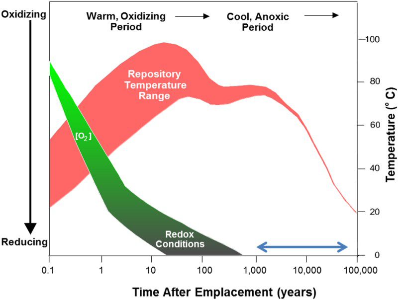
In our previous study [5], the characteristics of the sulphide films formed on the Cu surfaces were determined as a function of [SH−], [Cl−] and electrode rotation rate, and shown to fall into three categories: Type 1, a thin single layer, porous film observed at low [SH−] and a low sulphide flux; Type 2, a porous dual-layer film formed at intermediate [SH−] and higher fluxes; and Type 3, a passive, or at least partially passive film, formed at high [SH−] and transport fluxes. Since the Type 3 film displays passive characteristics and passivity is the pre-requisite for localised corrosion, it is critical for nuclear waste container safety assessments to determine whether susceptibility to localised corrosion, in particular pitting, is possible under DGR conditions.
The goal of this study is twofold: (i) to determine the mechanism of Cu2S film growth in 10−5–10−3 M sulphide solutions containing chloride in the concentration range from 0.1 to 5.0 M, since chloride is the dominant anion in the repository groundwater; and (ii) to determine whether or not the passive conditions required to support pitting are possible.
Experimental
Sample preparation
All experiments were performed with O-free, P-doped Cu provided by the Swedish Nuclear Fuel and Waste Management Company (SKB), Stockholm, Sweden. Working electrodes were machined Cu discs with a 1 cm diameter threaded with a stainless steel rod. For corrosion experiments, a non-conductive lacquer was applied to prevent the exposure of the steel/Cu junction to the electrolyte. Rotating disc working electrodes (RDEs) were prepared by setting Cu discs in a Teflon holder with epoxy resin. Prior to an experiment, electrodes were ground with a sequence of SiC papers (grit sizes: 600, 800, 1000, 1200, and 2400), then polished to a mirror finish using Al2O3 suspensions (1, 0.3, and 0.05 µm), thoroughly rinsed with Type I water with a resistivity of 18.2 MΩ cm (Thermo Scientific Barnstead Nanopure 7143 ultrapure water system) and dried in a stream of ultrapure Ar gas.
Electrochemical experiments
Electrochemical experiments were performed in a conventional three-electrode electrochemical glass cell placed inside a Faraday cage to reduce electrical noise. A cylindrical Pt sheet, rolled into a cylinder, was used as the counter electrode. A saturated calomel reference electrode (SCE, 0.242 V/SHE) was used in all experiments. All experiments were conducted using an RDE. The electrode rotation rate was controlled by a Pine Instrument Company Analytical Rotator Model AFA86 Serial 882, and electrochemical measurements were made using a computer-controlled 1287 Solartron potentiostat equipped with the CorrWare software. Prior to an experiment, the electrode was cathodically cleaned at −1.5 V/SCE to remove air-formed oxides, and then at −1.15 V/SCE. Voltammetric scans (CVs) were performed from an initial potential of −1.35 V/SCE to various anodic limits at a scan rate of 2 mV s−1. Electrodes were exposed to [SH−] of 10−5 M, 10−4 M, 5·10−4 M, 10−3 M and 2·10−3 M and [Cl−] of 0.1, 0.5, 1.0, 3.0 and 5.0 M. All solutions were prepared with Type I water, reagent-grade sodium sulphide (Na2S·9H2O, 98.0% assay) and reagent-grade sodium chloride (NaCl, 99.0% assay).
Corrosion experiments
Experiments were performed in an Ar-purged anaerobic chamber (Canadian Vacuum Systems Ltd), maintained at a positive pressure (2-4 mbar) by an MBraun glove box control system, to ensure anoxic conditions (cO2 < 1 ppm). The oxygen concentration in the chamber was analysed with an MBraun oxygen probe. Prior to an experiment, electrodes were cathodically cleaned as described in section ‘Electrochemical Experiments’. Experiments were conducted in solutions containing [SH−] of 5·10−4 M, and a [Cl−] of 0.1 M. All solutions used were prepared with Type I water and the reagents noted above.
Results and discussion
Film growth location
To identify the location of Cu2S film growth, an Au marker test was performed. A Cu specimen was first corroded in 0.1 M [Cl−] containing [SH−] = 5·10−4 M for 161 h to form a thin (∼200 nm thick) Cu2S film. The specimen was then removed, marked with a 200 µm wide Au line and re-immersed for a further 1530 h. Figure 2 shows the cross-sectional morphology observed using backscattered electron detection after a total immersion time of 1691 h. It is clear that film growth occurred on the Au marker since the thickness of the film below the marker remained unchanged; i.e. retained the same thickness as that of the preformed film. This indicates that film growth occurred at the Cu2S/solution interface and involved Cu+ transport through the film. As demonstrated previously, film growth at this sulphide concentration leads to a parabolic growth law [6], demonstrating the formation of a, at least partially, protective film. Inspection of the film in Figure 2 shows it to be, on average, ∼700 nm thick and compact.
(a) FIB cross-section of a corroded Cu specimen after immersion in 0.1 M NaCl + 5 × 10⁻⁴ M Na2S solution for 161 h prior to deposition of the Au marker and for a further 1530 h afterwards. (b) Higher magnification of the cross-section.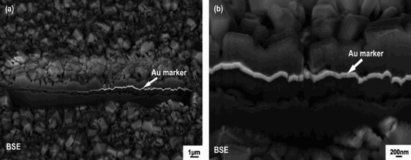
Growth of Cu2S under electrochemical conditions
Figure 3 shows two CVs recorded in 0.1 M [Cl−] containing 10−4 M [SH−], one under stagnant conditions, and the second at an electrode rotation rate of 52 rad s−1 (8.3 Hz). These experiments are similar to those performed previously [5], except the anodic limit was extended from the previous −0.7 V/SCE to −0.1 V/SCE to facilitate comparison to a similar set of potentiodynamic scans performed by Mao et al. [7]. These authors claimed that the currents measured over the potential range −0.8 V/SCE to −0.2 V/SCE were due to the growth of a passive Cu2S (possibly Cu2S/CuS) film with the current increase at positive potentials attributable to the Cl− induced breakdown of this passive film. The very large film reduction currents (observed over the potential range −1.0 to −1.3 V/SCE on the reverse potential scan) demonstrate that the current measured over the anodic potential range is due to porous Cu2S film growth. The shoulder observed on the cathodic peaks for both stagnant and rotated conditions (although subtle under stagnant conditions) corresponds to the reduction of a thin Cu2S film which grows (on the anodic scan) to a limited thickness before fracturing due to interfacial stress. The major peak corresponds to the reduction of the thicker, more porous Cu2S film [5], which grows on top of this thin fractured film, likely by a nucleation process. The increased anodic current observed when the electrode is rotated (between −0.8 V/SCE and −0.1 V/SCE), accompanied by the major increase in film reduction current on the reverse scan, shows that the film growth process is accelerated by the increased convective flux of SH− to the electrode surface. This indicates that film growth is controlled by the solution transport of SH− and not the transport of point defects in a passive film as claimed by Mao et al. [7]. In addition, irrespective of whether the electrode is rotated or not, the current is reversible (i.e. the same on the forward and reverse scans) over the potential range −0.9 V/SCE to −0.35 V/SCE, confirming that further film growth is uninhibited by the presence of the film already grown. This confirms that the film remains porous with its growth proceeding at the Cu2S/electrolyte interface, as demonstrated above in the Au marker experiment.
CVs recorded under stagnant and rotated conditions in 0.1 M NaCl + 10−4 M Na2S.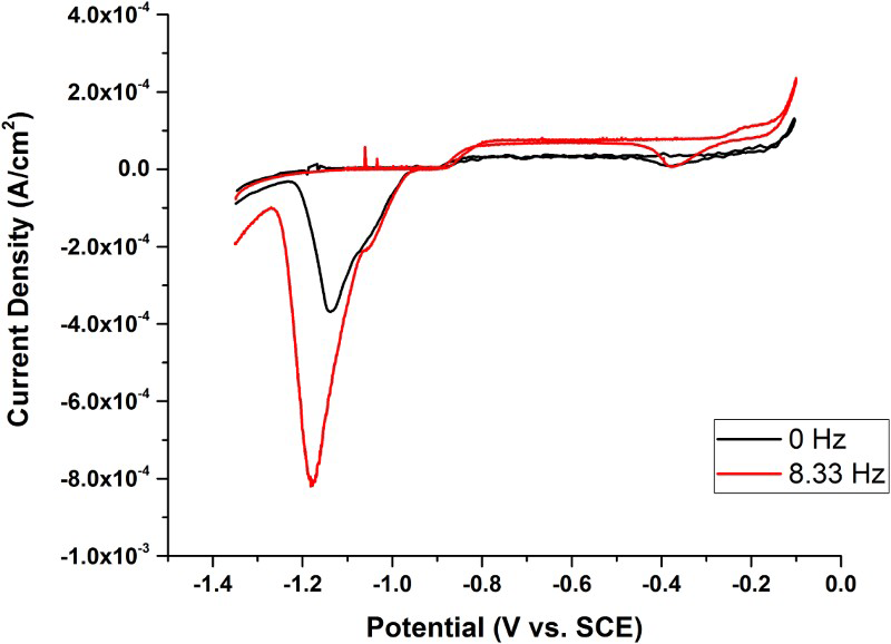
At potentials ≥−0.25 V the anodic current increases substantially under both stagnant and rotated conditions, Figure 3. Although not shown here, we observed a similar current increase at positive potentials in Cl− solutions in the absence of SH−. Consistent with the literature [8,9], this current can be attributed to the anodic dissolution of Cu as CuCl x (x–1)−, with the intermediate formation of a CuClads surface layer (reduced in the potential range −0.3 to −0.4 V/SCE on the reverse scan). The observation of this anodic/cathodic couple in this potential range, when a Cu2S film is present, Figure 3, confirms that the latter film, when present, is porous and does not passivate the surface.
These observations complement our previously published study conducted over a much narrower potential range (to a positive limit of −0.7 V/SCE) [5], in which the Cu2S film characteristics were determined as a function of [SH−], [Cl−], and the transport conditions at the surface, the latter controlled, as in the present case, at an RDE. We can now characterise the nature of the films according to the three categories previously proposed: Type 1, a thin single layer, porous film observed at low [SH−] and a low transport flux (i.e. low electrode rotation rate); Type 2, a porous dual-layer film formed at intermediate [SH−] and higher fluxes; and Type 3, a passive, or at least partially passive film, formed at high [SH−] and transport fluxes.
These results are summarised for solutions with low (0.1 M) and high (5.0 M) [Cl−] in Figure 4. These figures show the progression in film properties from porous Type 1 and Type 2 films to Type 3 films as the [SH−] and flux increase. These plots demonstrate that the passive conditions associated with Type 3 films are achievable only at high [SH−] and high fluxes in solutions containing 0.1 and 5.0 M chloride. Comparison of the plots also shows that [Cl−] only influences the type of film formed at very low fluxes when porous conditions prevail, and has no influence on the conditions under which passivity can be achieved; i.e. the range of conditions within which a Type 3 passive film can form.
Summary of the conditions under which porous (Types 1 and 2) and passive Cu
x
S (Type 3) films are formed as the electrode rotation rate and sulphide concentration are changed.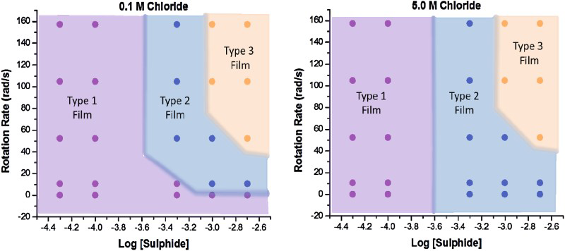
Influence of chloride on film growth
While the above results show Cl− has little influence on whether or not passive conditions can be established, it has been shown to influence the film growth rate, which is suppressed when the [Cl−] is increased [10]. In addition, the growth kinetics change from parabolic (0.1 M) to linear (0.5 M): that is, from a partially protective film to a more porous film supporting growth by the solution transport of SH−. Figure 5 shows that the limiting anodic current (recorded in the potential region −0.8 V/SCE to −0.4 V/SCE, Figure 3) is well below the theoretical value calculated via the Levich equation for complete transport control [11]. This confirms that Cl− has a direct inhibiting effect on film growth as observed in the corrosion experiments. In addition, although not large, the limiting currents show a complex dependence on [Cl−] with the current suppressed most at the highest concentration. This effect is presently under investigation. Since the Cu2S film is porous, suppression of the film growth process can be attributed to the access of Cl− to the Cu surface, confirming that the Cu2S film is porous, not passive. At these relative concentrations ([Cl−]/[SH−] ≥ 100), Cl− can displace chemisorbed SH−, thereby inhibiting the essential first step in the overall film growth process, Cu + (SH−)ads → (CuSH)ads + e−.
Limiting current for Cu2S film formation at −0.76 V/SCE from CVs recorded in 10−3 M Na2S containing various [Cl−]. 1 Hz = 2π rad s−1.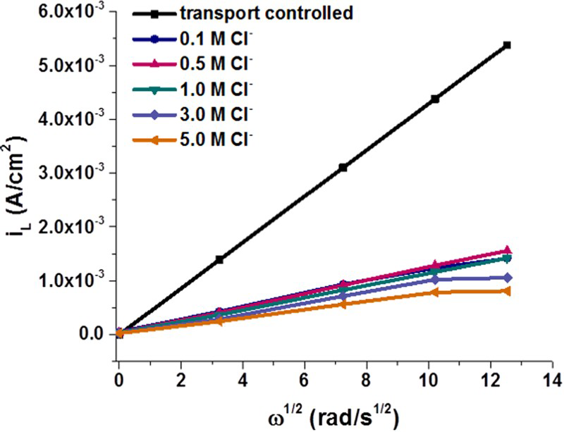
Summary and conclusions
The growth of Cu2S films on Cu in aqueous SH− solutions occurs at the Cu2S/electrolyte interface and involves the transport of Cu+ through the thickening film. Both corrosion and electrochemical studies show that the Cu2S film is porous, except at extremely high transport fluxes and [SH−] when passivity can be achieved. Since pitting requires the establishment of passivity, it is feasible only under high flux/high [SH−] conditions. The open circuit film growth rate and the anodic film growth rate are both suppressed at higher [Cl−] due to the displacement of chemisorbed SH− from the Cu surface. Film porosity also increases with increasing [Cl−].
Footnotes
Acknowledgement
The authors thank Christina Lilja (SKB) and Fraser King (Integrity Corrosion Consulting, Nanaimo, BC, Canada) for many helpful discussions.
Disclosure statement
No potential conflict of interest was reported by the author.