
Abstract
Tape-based discontinuous composite is a relatively new type of composite material that offers improved mechanical properties for similar process-ability compared to Sheet Moulding Compound or Bulk Moulding Compound. This makes it potentially attractive for the automotive industry. In this paper, a thin-ply carbon fibre reinforced polypropylene-based discontinuous composite is studied. Mechanical tests are performed to obtain the tensile, compression and shear behaviour of the material. The energy absorption via tearing is also studied to assess the suitability of the material for energy absorption applications, such as crash-boxes. The tearing test results show a large degree of plastic deformation and an advancing damage front leading to higher specific energy absorption via tearing compared to conventional composite materials.
Keywords
Introduction
Fibre-reinforced composites can be broadly classified into two categories based on the length of the reinforcement used: continuous and discontinuous composites. Continuous fibre reinforced composites offer higher mechanical properties due to their ability to carry and distribute higher levels of load in the fibre direction. However, these materials require significant effort to drape to complex shapes with multiple curvatures and geometric features, as seen in pressed automotive components. For high volume applications where low cost and short cycle-time are of importance, lack of formability is a drawback. This problem can be solved by using discontinuous composite materials which have good formability, however at the expense of mechanical properties.
Recently a new form of material called tape-based discontinuous composites (TBDCs) have garnered attention due to its ability to bridge the gap between mechanical performance and manufacturability. By using pieces of tape as reinforcements instead of random loose fibres, the overall performance of the discontinuous composites can be increased as demonstrated by Feraboli et al. [1], Wan and Takahashi [2] and Pimenta and co-workers [3, 4]. The micro-structure of these materials has been observed to replicate the layer-by-layer structure of a conventional continuous fibre-based laminates. This order is lost in traditional random fibre composites [2] which have swirled fibres in all directions.
Another influencing factor for TBDCs improved properties is the out-of-plane misalignment of fibres. Such misalignment of fibres, normally found in random fibre composites [5], contribute negatively to the overall in-plane mechanical properties of a composite. Apart from the distribution method which can induce variations, Li et al. [3] showed that tape thickness can also influence out-of-plane misalignment. In their study, thin and thick tapes were used to make discontinuous composites and it was observed that larger misalignments tend to be found in thick tape based discontinuous laminates. In addition larger resin rich areas were also found resulting in lower strength for thick tape based laminates. In subsequent modelling studies of tape pull-out and tape fracture strength, the influence of tape thickness was evident [3, 6]. The effect of in-situ strength was not studied in these works, which can be significant especially for thin-ply based discontinuous composites [7, 8].
Extensive research has been done to characterise tensile properties of TBDCs [1-4, 9-12]. Feraboli et al. [1, 9, 10] characterised carbon-epoxy TBDCs manufactured with a vacuum bag—autoclave curing process and showed that the stiffness of the laminate was comparable to that of quasi-isotropic (QI) continuous fibre based laminates. This was not observed for the strength properties which were considerably lower than QI reference values. The measured stiffness however, showed similar or in some cases larger scatter in comparison to the strength. This variation was visible in the Digital Image Correlation (DIC) full-field strain measurements as scattered hotspots (low stiffness areas). This highlights some of the difficulties to characterise and model TBDCs. Due to the large strain gradients along the length of specimen, a strain gauge of length comparable to the specimen length is required [9]. Therefore, in the current study, DIC is used for strain measurements.
Thermoplastic TBDCs have been characterised in tension and compression by Wan and Takahashi [11, 13]. A 40 μm thick carbon-polyamide 6 tape was used to make laminates using a paper making process. The effects of tape size (length x width) and laminate thickness have also been studied [13, 14] with a trend of increasing strength with both tape length and laminate thickness. The tensile stiffness and strength increase until they reach an asymptotic value after which there is no increase with change in thickness of the laminate. This behaviour of TBDCs have been confirmed in other studies as well [1, 12].
Compression tests on the discontinuous composites were performed by Feraboli et al. [1], Wan and Takahashi [11] and Selezneva and Lessard [12]. The compressive stiffness was similar to the tensile stiffness in all the cases reaching close to continuous fibre QI laminate reference. The compressive strength was similar to or higher than that of the tensile strength for the case of carbon-epoxy and carbon-PEEK TBDCs [1, 12]. Wan and Takahashi [11] studied the dependence of the mechanical properties of the laminate on processing conditions of carbon-polyamide 6 thin-tape based TBDCs. It was observed that strength and failure mode are dependent on the processing conditions for thermoplastic composites. Compression specimens made at low moulding pressure failed at considerably lower stress as compared to high pressure moulded TBDCs. Lower moulding pressure specimens failed in buckling compared to specimens manufactured at higher pressures which showed higher strength and failed by transverse shear failure.
Fewer studies have been performed to measure the shear performance of tape based discontinuous composites [12, 15]. In these studies, the in-plane shear stiffness and strength were evaluated with V-notched specimen based test methods: the Iosipescu shear test (ASTM D 5379) or with V-notched rail shear test (ASTM D 7078). Rail shear tests use specimens which have a large gauge section and are face loaded. The large surface available for load transfer makes it a good choice for laminates with high shear strength. In comparison, the Iosipescu test uses specimens which have smaller gauge section and are edge loaded, limiting the tests loading capacity. The highest risk in Iosipescu tests is that of premature failure of the specimen by crushing at its edge because of high compressive stresses. The choice of testing method therefore depends on expected shear strength of laminate and the size of representative unit cell of the material. Selezneva and Lessard [12] used the V-notched rail shear test to characterise the shear behaviour of CF-PEEK TBDCs and their continuous fibre counterparts to show the non-uniformity in shear strain and failure paths in the gauge section. In their study, only TBDCs with lower shear strength (specimens made of shorter tapes) were successfully tested. The higher strength specimens were susceptible to slippage in the clamping region, an issue that was also observed when testing thicker specimens [15]. However, the in-plane shear strength was found to be comparable to that of a continuous QI laminate, which was not the case in tension and compression.
The energy absorption properties of discontinuous composites have not been widely studied. Crash energy absorption applications generally utilise continuous fibre based composite structures to dissipate energy through progressive failure of the laminate. For such cases, maximum energy absorption is achieved by inducing the maximum amount of fibre fracturing while minimising delamination, buckling or fibre splaying in the laminate. An alternative energy absorption mechanism, tearing of bolted joints shown in Figure 1, has been investigated by Heimbs and Bergmann [16] as a way to dissipate crash loads in aircraft fuselage structures.
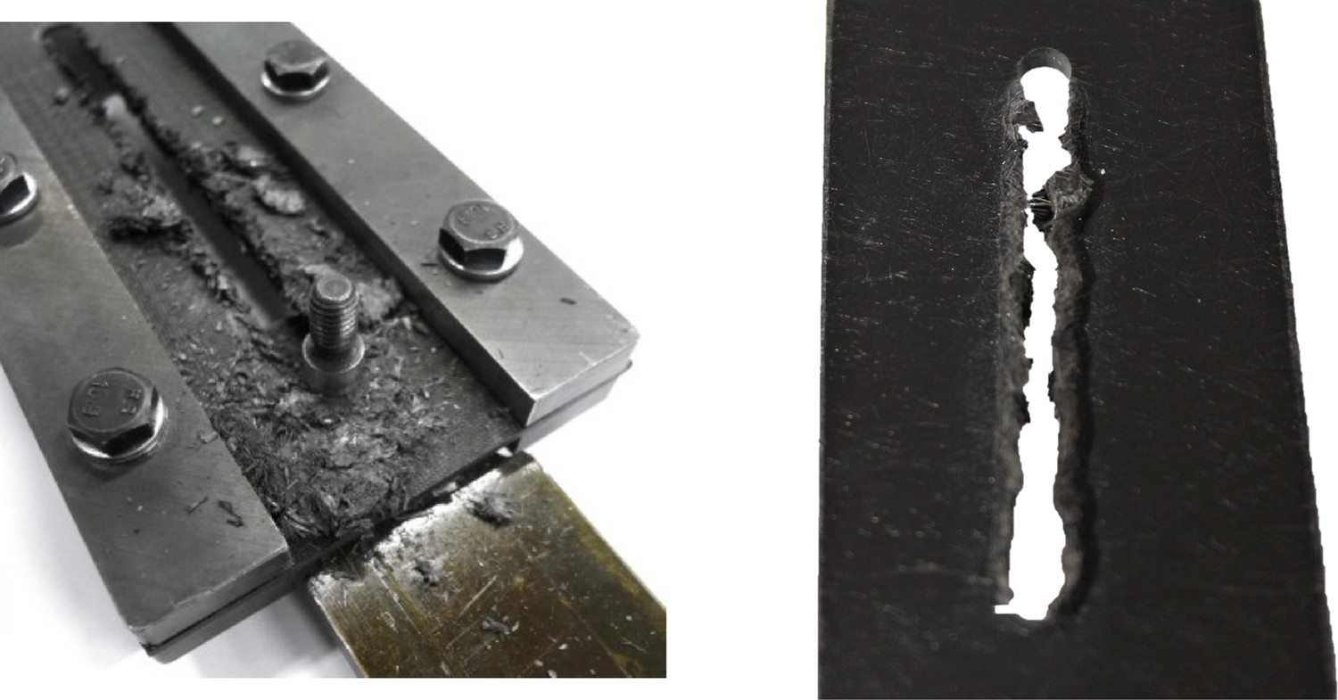
Tearing failure offers a stable way of absorbing energy compared to the generally adopted method of crushing of tubes, which can be unstable. While Heimbs and Bergmann used continuous fibre composites for their test, it was proven that it can be equally effective on short fibre composites [17]. These results are encouraging and make TBDCs an interesting material to be investigated for tearing energy absorption properties.
With this in mind, the objective of the paper is to characterise CF-PP TBDC for assessment of its mechanical and crashworthiness properties. Towards this goal, TBDCs are characterised in tension, compression and shear. Tearing energy absorption capacity is characterised by performing a bearing test. The results of the mechanical and energy absorption tests are used to compare TBDCs performance with conventional composites and assess their suitability for crash application.
Materials
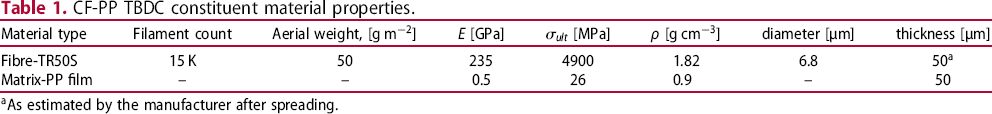
 . A polypropylene (PP) film made of Moplen RP220M polymer [18] from Lyondell Basell grafted with 3 wt% maleic anhydride was used as the thermoplastic matrix material. The thickness of the film was 50 μm which was approximately equivalent to carbon fibre tape thickness. The properties of the fibre and PP film used for manufacturing CF-PP TBDCs are given in Table 1.
CF-PP TBDC constituent material properties.
CF-PP TBDC constituent material properties.
 ]
] [MPa]
[MPa] ]
]
 As estimated by the manufacturer after spreading.
The 20 mm wide dry carbon fibre tape was cut into 50 mm long pieces using an automatic tape cutting machine to produce repeatable and accurate tape lengths. Matrix in the form of polypropylene film was cut from a roll using scissors such that its size was slightly larger than the size of the mould. Layers of PP film and fibre were then stacked manually to produce a quasi-isotropic stack of
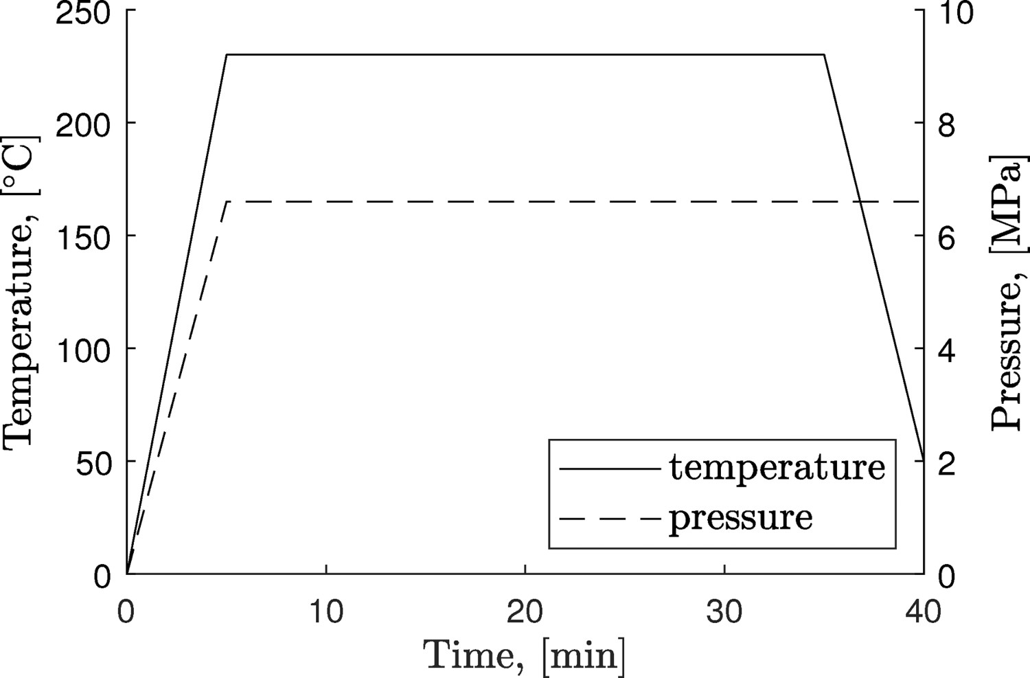
Manufacturing process of TBDCs, (a) single UD CF-tape discontinuous layer, (b) QI stack of discontinuous composite and (c) consolidated TBDC laminate. Process history of CF-PP TBDCs. as shown in Figure 2. The final symmetric and balanced layup
 was obtained by repeating the number of quasi-isotropic stacks (n) until the desired laminate thickness was achieved, with symmetry maintained by mirroring the stack from half the thickness. A single extra layer of PP film was added on the top of the stack. The preform stack was then cut to
 mm to fit in the compression mould, where it was processed at 6.6 MPa pressure and
 C (as shown in Figure 3) to form a consolidated laminate. In total, 10 plates were manufactured using this method.
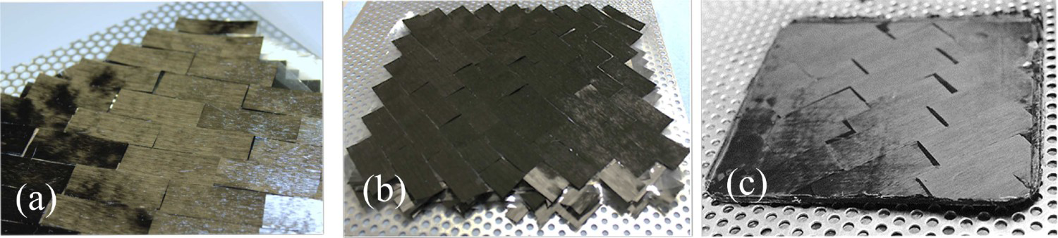
The reason for using a quasi-isotropic layup with layered approach was two-fold: firstly to obtain laminate properties equivalent to what is achieved during random distribution of chopped tape composite as shown by Pimenta et al. [3, 4], and secondly to ensure maximum wetting of fibres from the PP film. To be a viable and commercially appealing material, in the future an automatic process must be developed to distribute (pre-impregnated) tapes such that quasi-isotropic behaviour can be achieved.
Fibre volume fraction (
 ) was measured by a resin burn off test. A rectangular piece of specimen weighing 3 g was machined out of the laminates. A total of 7 specimens were machined from different location of the laminate and investigated. The samples were heated at
 C for 4.5 h in a muffle furnace. After cooling down, the crucible was weighed again to calculate the fibre volume fraction.
Mechanical tests
Tension, compression and shear tests were performed in a Shimadzu Universal testing machine with a 50 kN load cell. For the case of tension, two different thickness were studied. Five specimens have been tested for each test except for the tension test of thick laminates for which only three specimens were tested. To map the strain field, a DIC system was used for all the test cases. Tearing tests were performed on specimens with three different widths. For each width, five specimens were tested to study the effect of width to diameter ratio.
Tension tests
Tension tests were carried out according to ASTM D3039 [19]. The length of the specimen was however altered from the standard due to limitations in mould dimensions. Two specimen thicknesses were used to study the effect of thickness on mechanical properties. Tensile specimens
 mm were cut out of the laminated plates of thickness 1.2 and 3.1 mm using a band saw. To study the in-plane isotropy of the laminate, specimens were cut in 0 and 90 directions from different plates. Glass-fibre/epoxy laminate of 1 mm thickness was used as tabbing material. The edges of the specimens were polished by hand using fine grit sandpaper to remove undesirable defects induced from cutting of the specimen. The gauge section after tabbing was limited to approximately 90 mm, which was used to measure strain with a DIC system. The tests were carried out at crosshead displacement rate of 1 mm/min.
Compression tests
The compression specimens were fabricated following the ASTM standard D6641 [20]. A modified combined loading compression (CLC) test fixture was used to accommodate DIC strain measurement as shown in Figure 4.
Compression test setup with DIC system and modified CLC fixture.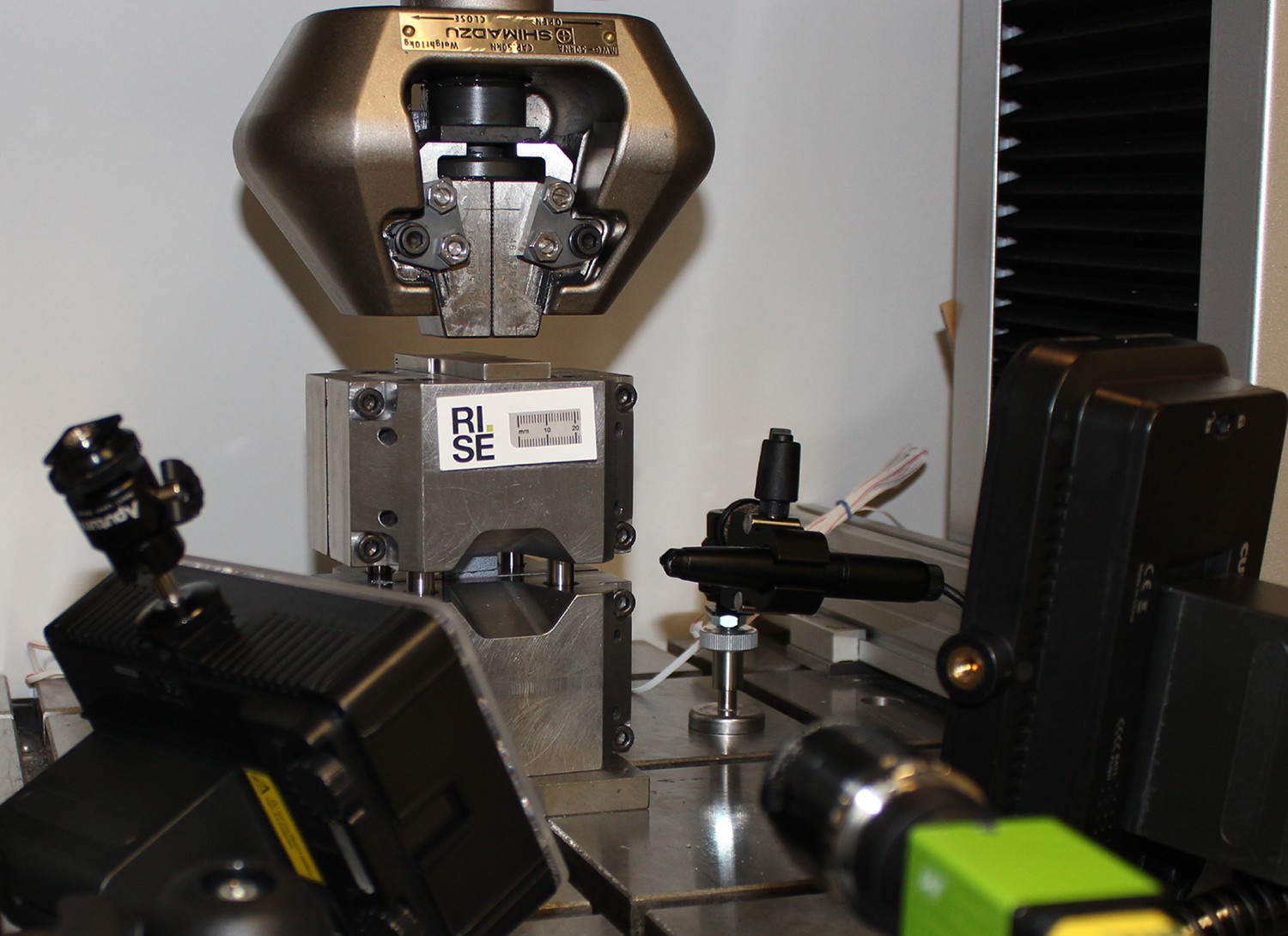
Specimens of size
 mm (length x width x thickness) were used without tabs. The edges of specimens were ground to achieve flat and parallel surfaces. Specimens were tested at a crosshead displacement rate of 1 mm/min. The strains were measured using DIC on the front side of the specimen and strain gauges were mounted on the back side to monitor bending of the specimens.
ASTM D5379 Iosipescu shear tests with V-notched specimens [21] were performed to study the shear behaviour of the material. Achieving a homogeneous strain distribution in the notch region of the specimen can be challenging for anisotropic materials, and requires some alterations to the specimen design stated in the standard [21]. Modified versions of V-notch specimens proposed by Melin and Neumeister [22] were shown to be effective in producing homogeneous shear strains in the notch region. These guidelines were followed for the Iosipescu specimens used in the current study. The dependence of notch angle (
 ) on degree of anisotropy of the laminate is given as,
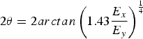
 for an in-plane isotropic TBDC laminate. Specimens of size
 mm
mm
 were machined from TBDC laminates. The V-notched gauge section of 11.6 mm height with notch radius of 1.5 mm were machined into the specimen. To reduce the risk of edge crushing, specimens were tabbed with 2 mm thick glass/epoxy laminates. Tests were carried out at a crosshead displacement rate of 1 mm/min. DIC was used to measure the shear strain between the notches of the specimen as the average over an area of
 mm.
mm.
Tearing tests were carried out using a double lap shear test setup shown in Figure 5, which is developed for a ASTM D5961 bearing test [23].
Tearing test setup according to ASTM Bearing standard D5961 (left) and specimen used for tearing that allows for tearing of around 90 mm (right).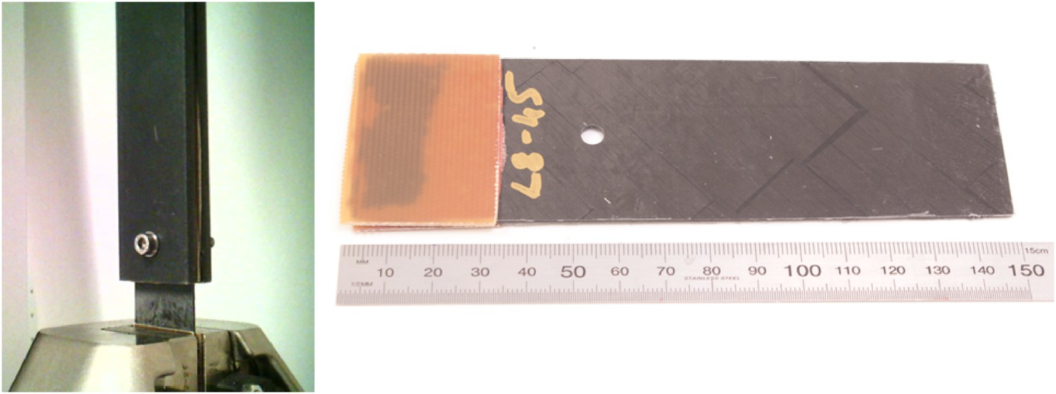
Specimens of length 150 mm and thickness of 1.2 mm were used to study the effect of width to hole diameter ratio (w/D) on energy absorption during tearing. Three sets of specimens with w/D
 and 9 were tested with a hole diameter of 5 mm which was kept constant for all the specimens. For the purpose of energy absorption characterisation the edge distance from the untabbed end was increased to maximise tearing distance as shown in Figure 5. Tests were performed at a rate of 5 mm/min with a 50 kN load cell.
Constituent properties
Data from the manufacturers indicated that the film and dry tape were approximately equal in thickness and areal weight (i.e,
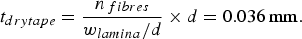
Micro-structure of the CF-PP TBDC. m/50 gsm). Using this, a theoretical estimate of the final laminate thickness was calculated with known dimensions of fibre, tape and PP film as stated in the experimental section. Assuming tight packing of fibres, the thickness of the dry tape (
 ) and resulting lamina (
 ) can be calculated as:
 is width of the lamina,
 is the width of the film, d is diameter of fibre,
 is filament count and
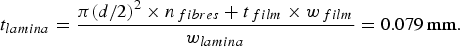
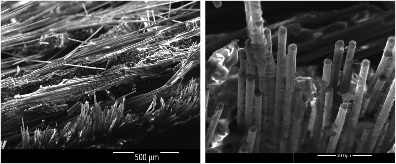
 is thickness of the PP film given in Table 1. The theoretical estimate of thickness of the TR50S dry fibre tape assuming a tight packing can be as low as 0.036 mm (or 36 μm). Lamina thickness can be as low as 0.079 mm. This was experimentally verified by analysing the cross-section of laminate. A specimen was cut along the y-direction (which aligns with direction of placement of 0 degree tape pieces) and examined under microscope to study the micro-structure. From Figure 6, it can be seen that the tape thickness measure from the micrograph is close to the theoretical estimate calculated above. The micrograph also indicates that the tape pieces have low out-of-plane misalignment-in comparison to SMC type materials, that helps in creating a laminate type micro-structure.
Similarly an estimate for fibre volume fraction can also be found. Assuming no voids, the theoretical fibre volume fraction is the ratio of area of fibres to area of matrix, which gives
 . After processing and conducting resin burn-off tests it was found that
 was
was
 . It can be seen that the measured
 comes close to the theoretical value for a laminate with no voids. The small variation seen in measured value could possibly be due to the presence of voids and other artefacts such as gaps and overlaps of tape pieces.
Tensile properties
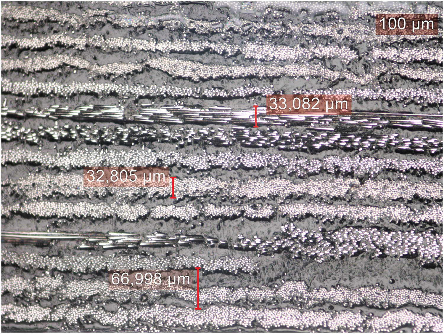
The stress-strain response for in-plane tensile tests of CF-PP TBDCs are shown in Figure 7. Two different thickness of specimen were tested, 1.2 mm and 3.1 mm. The average Young's modulus of the thin specimens is
(a) Tensile stress-strain curves of the thick and thin CF-PP TBDCs, (b) DIC strain field of thin specimen which shows larger distribution of hotspots and (c) DIC strain field of a thick specimen with low number of hot spots. GPa and the average tensile strength is
 MPa. The measured coefficient of variation for stiffness is 14.4% compared to 6.2% for strength. For thicker specimens, average Young's modulus is
 GPa and strength is
 MPa. The coefficient of variation for both stiffness and strength is 2%.
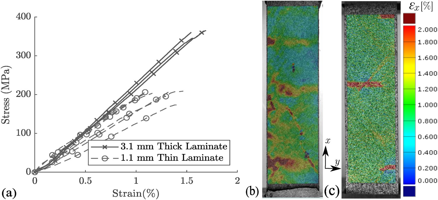
Specimens showed a linear behaviour in tension with brittle fracture at failure. The failure surface in Figure 8 shows different types of failure modes. The off axis tapes in Figure 8 are largely observed to have failed in fibre pull-out failure mode. While the tapes oriented parallel to loading direction appear to have undergone fibre pull-out and fibre fracture failure modes as shown in Figure 9.
Fracture surface of CF-PP TBDC tensile specimen. (left) Fracture patterns observed on TBDC specimen, (right) tape pullout and fibre fracture seen on tapes.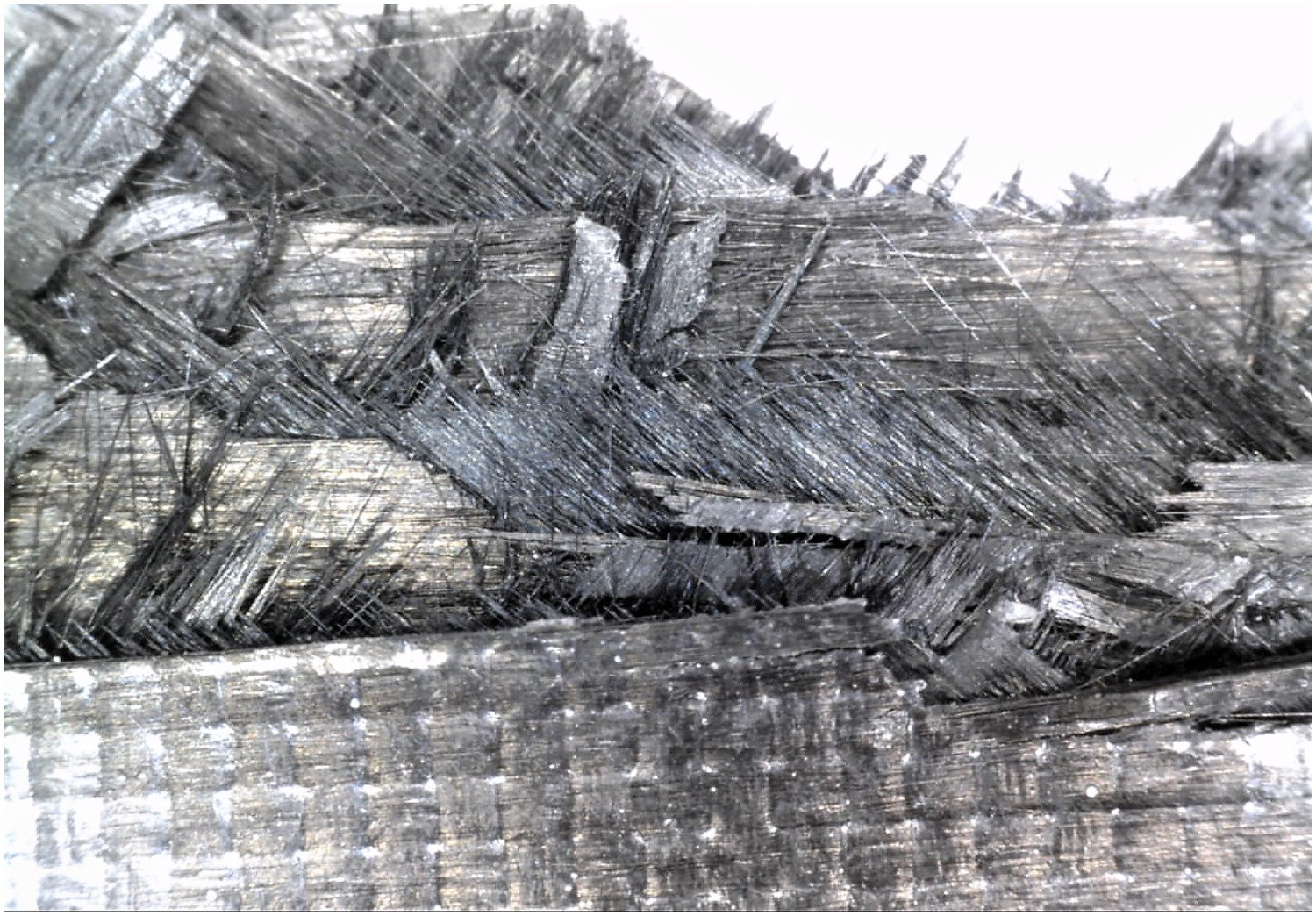
The results show an increase in stiffness and strength and a decrease in scatter of the results with increasing specimen thickness. Similar behaviour of TBDC has been reported by Takahashi et al. [14] and Selezneva and Lessard [12]. One explanation for this can be the improved homogeneity due to increased number of layers. The thicker specimens consist of 40 layers each of carbon fibre and PP film compared to 16 layers for the thin specimens. The effects of variability in fibre direction and gaps and overlaps between tapes will be more prominent for thinner specimens and likely to have larger influence on mechanical properties.
Evidence for this argumentation can be seen in Figure 7(b,c), where the DIC strain fields are shown. It is clear that number and size of high strain regions visible on the specimen surface is lower for thicker specimens. Since the strain fields are averaged over the entire gauge section, the scatter is directly dependent on the number and size of hotspots on the specimen surface which is stochastic for TBDCs. Considering that the laminates have been manually stacked with a given layup, high randomness of fibre angle distribution seen in other manufacturing methods(such as pressing SMC) can be neglected as a primary cause, although a certain level of human error should be assumed. Therefore, the effect of gaps and overlaps, and number of layers must be more significant to the mechanical performance. It has also been shown before in [13, 14] that the mechanical properties tend to show asymptotic behaviour whereby there is no increase in mechanical properties with increased thickness above a given limit. Further testing is required to obtain a clear estimate of the asymptotic value of mechanical properties for the materials discussed here.
The applied compressive stress is plotted against the average strain over the gauge section (
Compressive stress-strain curve of the CF-PP TBDC (left); Compressive failure modes of CF-PP TBDC: delaminations, macro-kinking is visible in the picture (right). mm) in Figure 10.
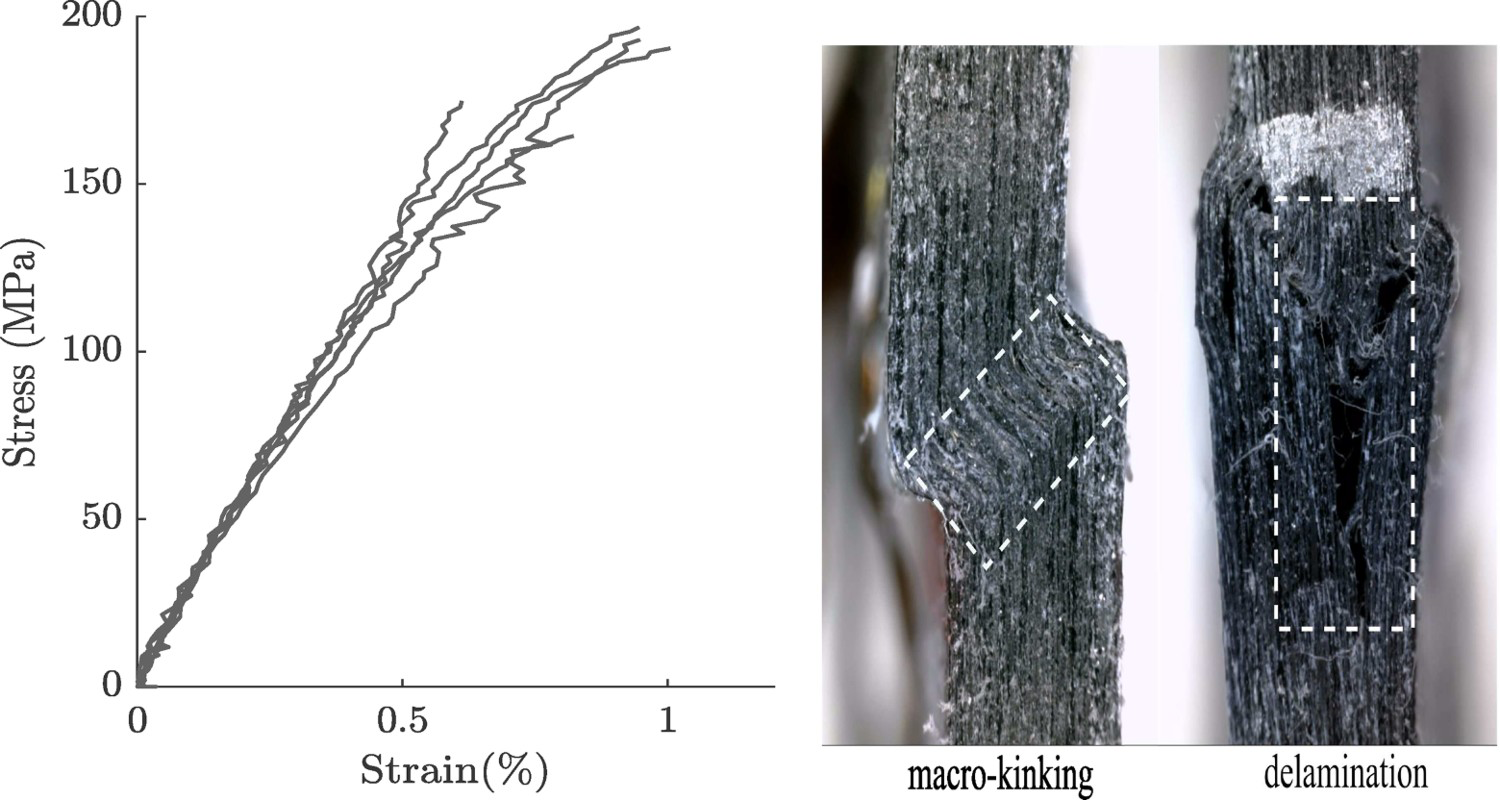
The stress-strain response shows a slight non-linear behaviour in compression. The average Young's modulus for specimens in compression is
 GPa and the strength is
 MPa. Hence the compressive stiffness is slightly higher than the tensile stiffness, and the strength is lower in compression compared to tension. The strain reading from front side of specimen (DIC) and back side of the specimen (strain gauge) indicate that the level of bending was within the acceptable limit of
 as recommended in the ASTM standard D6641 [20].
The variation in modulus and strength between specimens are 4% and 6% respectively. Since the gauge section available for DIC measurements in compression test is smaller than that of tensile tests, the effects of hotspots are much smaller. The failure modes seen in the compression tests were predominately macro-kinking, as shown in Figure 10. In the vicinity of the kinked region, delaminations were also observed. For all test specimens failure occurred within the gauge section, approximately in the middle as seen in Figure 11.
DIC strain field for TBDCs under Compression, (left) DIC strain field right before failure at
 % strain; (right) after failure.
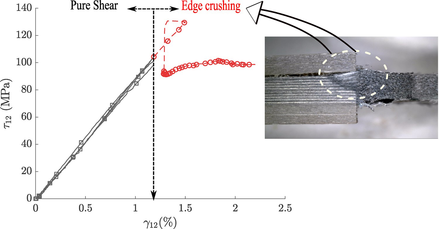
The initial tests done on tabless specimens showed evidence of edge crushing (see Figure 12). The specimens tend to deform the at the edges, before failing in shear. The tabbing of specimen helped to delay the edge crushing considerably.
Edge crushing on tabless specimen.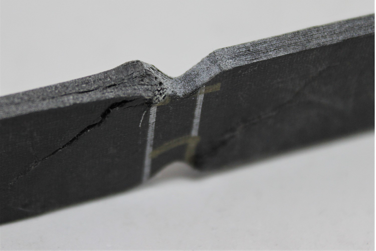
The shear stress
Shear Stress vs Strain curves of CF-PP discontinuous composites. and averaged shear strain between V-notches from the DIC measurements is used to plot the response of CF-PP TBDC material shown in Figure 13. Average shear modulus of the TBDC is 9.0 GPa. The material displays a linear shear response up to 100.0 MPa. A clear shear strain localisation is visible in the specimen centre region from the DIC strain fields in the early part of test. After 100.0 MPa, localised crushing of the edges intensifies, causing redistribution of the load and relieving of the shear stresses in the notch section of the specimen. This causes shear stress to gradually reach a plateau as can be seen in Figure 13. The reported value of shear strength is therefore a conservative estimate, since the specimens failed prematurely in edge crushing. The measured in-plane mechanical properties of the composite are presented in Table 2.
Results from in-plane mechanical testing of CF-PP TBDCs.
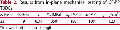
 , [MPa]
 , [MPa]
 ]
]
 A lower limit of shear strength.
The results from the tearing tests are shown in Figure 14 for specimen widths of 25, 30 and 45 mm respectively. For all of the specimens irrespective of the width, a linear increase in load is seen until it reaches a knee point, after a displacement of approximately 1 mm at 750 N. After the knee point is reached, the response continues to be linear until it reaches a relatively stable region where the damage progresses smoothly. This response is close to a linear elastic-ideally plastic material and was observed for all the specimens.
(left) Force vs displacement curves for different w/D ratios, (right) extend of Tearing damage in the specimen with different w/D ratios.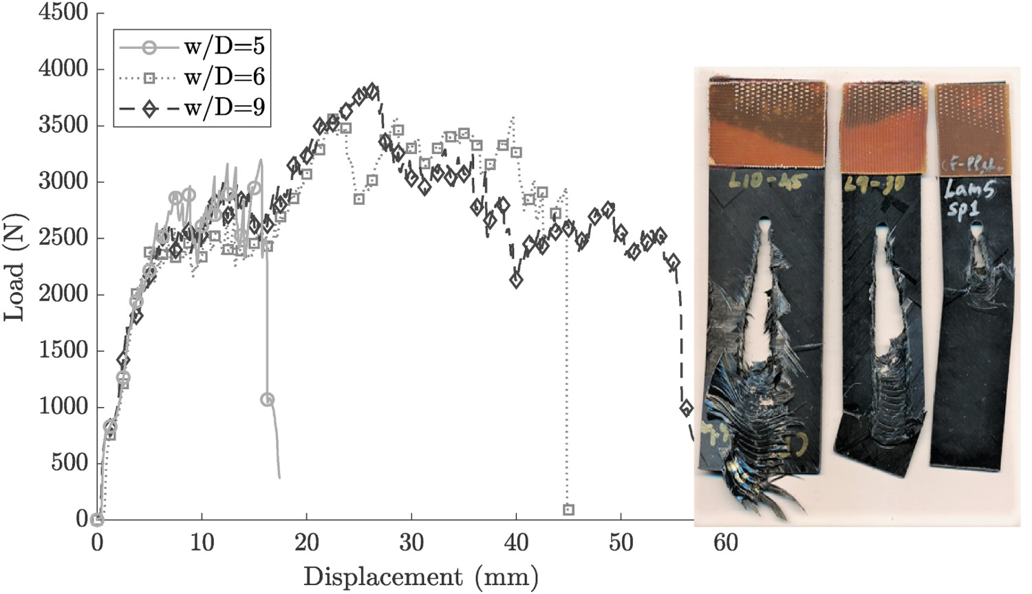
Bearing damage can be observed after 2 mm displacement of the pin as shown in Figure 15. The specimen was investigated under a microscope to understand the initiation of damage. The micrographs in Figure 16 show that the laminate tends to splay outward under compressive stress resulting in bending of the outer layers similar to what is often observed in conventional crushing of composite tubes. The inner tape pieces tend to separate from each other due to poor impregnation. This can be seen in the layers close to mid-plane. In the subsequent loading (after 3 mm, see Figure 16) the separated layers are deformed and crushed inwards.
Initiation damage after 2 mm and 3 mm pin displacement. Damage and tape separation after 2 mm displacement (left) and damage after 3 mm displacement (right).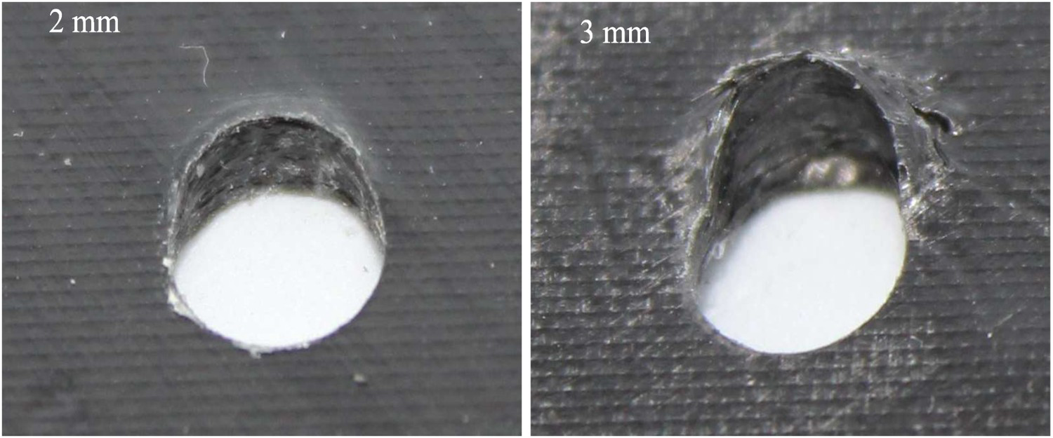
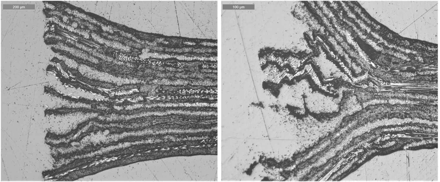
When the specimen is loaded after damage initiation, the material is pushed ahead of the bolt to form wrinkles and a progressive damage front advances ahead of the bolt. Multiple wrinkles occur during the course of the test and the damaged area forms a ripple-like zone. The deformation pattern is shown in the micrograph of the damaged area in Figure 17. This is quite unique, and is possibly inherent to the layered structure of the high stiffness impregnated fibres interleaved with resin rich PP layers. This type of plasticity mechanism is not common in composites, but more common in ductile materials like metals.
Deformation of the material around the bolt post tearing test.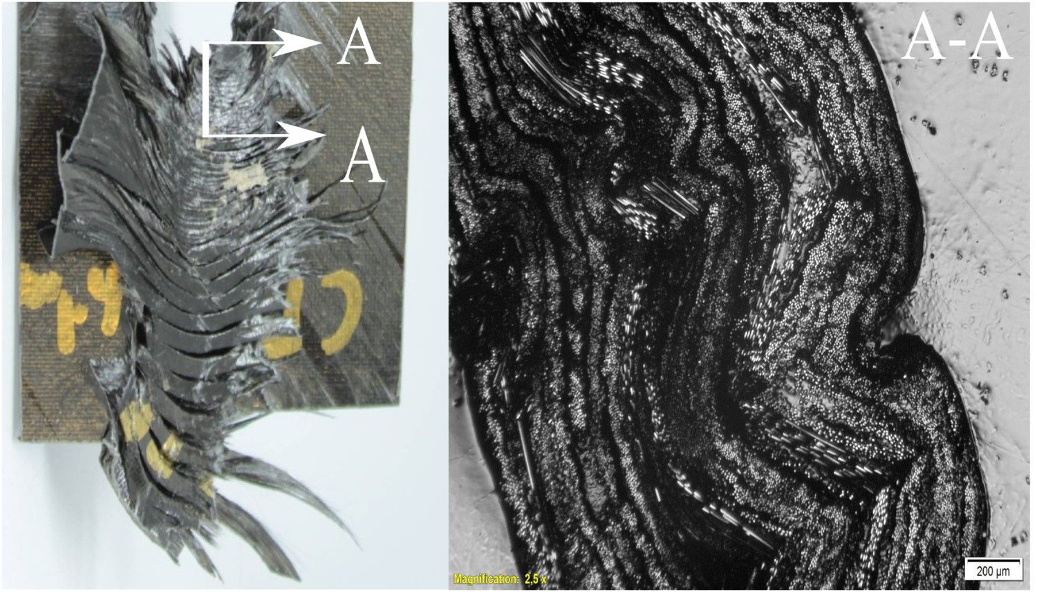
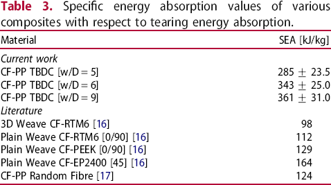
To assess the performance of the TBDCs it is important to compare the specific energy absorption (SEA) with values from the literature for traditional continuous fibre reinforced composites [16, 17]. SEA is calculated by dividing the energy absorption from load–displacement curve in Figure 14 by the mass of material along the torn distance as given in Equation (4).
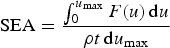
 is the maximum displacement, F is the applied force, ρ is density of the material and d is the diameter of the pin. It is clear from Equation 4 that it is advantageous to maximise the tearing distance for increasing energy absorption. From Figure 14 it is evident that the bolt travelled the longest distance for 45 mm width specimens (
 ) and the shortest for 25 mm specimens (
 ). This is because the ripple-like zone grows in width as the bolt travels and continues to grow until the specimen fails in net-section failure. This happens at around 18 mm of displacement for the specimens with ratio
 , limiting the energy absorption capacity. Considerable improvement is attained for specimens with ratio
 and 9. For these specimens the bolt travels around 45–50 mm and 55–60 mm respectively.
Specific energy absorption values of various composites with respect to tearing energy absorption.
Mechanical properties of CF-PP TBDC manufactured using compression moulding are studied in this paper. The equivalent laminate analogy with layered manufacturing approach was used in order to obtain a laminate micro-structure with reduced out-of-plane misalignment. The low fibre volume fraction and high plasticity of the matrix created a unique deformation mechanism. Tensile failure of laminate was however a brittle failure, with failure mechanism being predominantly in tape pull-out mode. It was also observed that tensile failure strength showed small scatter compared to tensile modulus. In compression, failure was initiated by delaminations which were also seen during the tearing damage initiation study. The compressive response was close to linear with some specimens showing slight non-linearity. Compressive strength was notably lower than that of in tension. Iosipescu shear testing provided a clear estimate for stiffness while for strength the test method yielded a lower limit due to premature edge crushing failure.
The TBDCs tested here show excellent energy absorption properties. Tearing tests resulted in plastic deformation of specimens often seen in ductile materials, which could be related to the layered structure of the laminate that contains tapes interleaved with PP films. The tearing mechanism appears to be stable and repeatable with load reaching a plateau consistently for all the specimens tested. This shows that CF-PP TBDCs used in tearing can potentially be an alternative method for reliable lightweight energy absorption.
Footnotes
Acknowledgments
This work has been performed as part of the ICONIC project under European Union's Horizon 2020 research and innovation programme, grant agreement no. 721256. The authors wish to thank Oxeon AB and Queens University of Belfast for providing the material for manufacturing.
Disclosure statement
No potential conflict of interest was reported by the author(s).