
Abstract
For parts produced by fused filament fabrication (FFF) the adhesion between the first printed layer and the printing bed is crucial, since it provides the foundation to the subsequent layers. Inadequate adhesion can result in poor printing quality or destroyed bed surfaces. This study aims at understanding and optimising the adhesion process for parts produced by FFF. The consequences of varying printing bed temperatures on the adhesion of two commonly used printing materials on two standard bed surfaces were investigated by means of an in-house built adhesion measurement device and complemented by contact angle measurements. This study shows a significant increase in adhesion forces, when printing parts at a bed temperature slightly above the glass transition temperature of the printing material.
Keywords
Introduction
Fused filament fabrication (FFF) or fused deposition modelling (FDM) is an extrusion-based additive manufacturing technique, which relies on the extrusion of thermoplastic filaments to produce a three-dimensional object in a layer-by-layer manner [1]. The adhesion of the first printed layer onto the printing bed is critical, as without proper adhesion the final part cannot be built [2]. Inadequate adhesion results in poor-quality printed objects, likely due to shifts, warps or delaminations of the object during the printing process [3]. Therefore, the adhesion between the extruded polymer and the printing bed should be high enough to keep the printed object in place during printing. On the other hand, after printing the adhesion should be low enough so that the part can be removed easily from the printing bed without damaging the produced part and the bed surface [4].
FFF printers are commonly composed of printing beds made of glass or polymers [2]. The printed objects are supposed to adhere consistently onto these surfaces. However, this is not always the case. Thus, to improve the adhesion of the first layer to the printing bed, several things are recommended: (i) to clean the printing surface to remove grease and residues from the bed; (ii) to level the printing bed so that the first layer is in close contact with the printing bed; (iii) to cover the printing surface with polymeric films or tapes like polyimide (PI) or blue painters tape; (iv) to slightly increase the tape surface roughness by sanding it; (v) to apply water-soluble glues, hair sprays or special coatings; (vi) to print on a plate or film of the same material that is being printed; (vii) to print on cleated surfaces; and (viii) to increase the temperature of the printing bed to a recommended value for a given material [2, 3, 5-7].
Methods (i–ii) are known prerequisites done before every printing. Methods (iii–vii) require the application of additional materials on the printing bed, which may be difficult to apply. Based on our experience, the risk of uneven printing bed surfaces caused by overlapping seams, folds, creases or air bubbles, is drastically increased when using methods (iii–iv). In this context, one practical solution is to increase the bed temperature to improve the adhesion of the printed material onto the printing bed during printing. However, directly after printing, a non-destructive removal of the printed part may not be attainable at this bed temperature. If the occurrence of welding can be precluded, it may be favourable in this regard to cool the printing bed first to a certain temperature, at which the adhesion forces are sufficiently reduced. Two main problems arise. The first problem is to determine this operational temperature range, whose upper limit, effective during the print, ensures sufficient adhesion during printing, and whose lower limit, adjusted after the completion of the print, provides little adhesion for the removal of the part. Second, the determination of the best material combination of the printing bed and the filament is critical, e.g. to avoid excessive welding, especially when using novel materials.
So far, no study revealed any strategies on identifying an optimal printing bed temperature range for various materials and its effect on the adhesion of samples produced by FFF in a systematic manner. For this reason, the present work attempts to close this gap by evaluating the adhesion forces by means of an in-house developed device that measures the forces required to shear-off printed strands from printing surfaces at different temperatures. Using this device, the effect of temperature on the adhesion of two commonly used printing materials, namely acrylonitrile-butadiene-styrene (ABS) and polylactic acid (PLA) onto two different printing surfaces (glass and PI) was investigated. Moreover, these measurements were complemented by surface tension measurements and morphology analyses of the topography of the contact area. The systematic approach in the present work illustrates an efficient way to optimise the adhesion of different printing materials on various printing bed materials. Especially for novel material compounds, this methodology is of great importance for a reliable printing process.
Experimental
Materials
The glass transition temperature TG, the density ρ, the specific heat capacity at constant pressure CP and the thermal conductivity λ of the materials investigated.
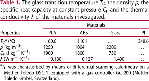
aTG was characterised by means of differential scanning calorimetry on a Mettler Toledo DSC 1 equipped with a gas controller GC 200 (Mettler Toledo GmbH, Switzerland).
Printer settings
A Hage 3DpA2 (Hage Sondermaschinenbau GmbH & Co. KG, Austria) with a brass nozzle of 0.5 mm in diameter was used for the production of the adhesion test specimens (see section ‘Adhesion measurement’). A constant extrudate flow rate of 2 mm3 s−1 and a printing speed of 50 mm min−1 were kept constant for all specimens. As the adhesion of printed parts is dependent on the first layer height [5], the layer thickness of the first layer was set constant to 0.2 mm. For PLA and ABS die temperatures of 220 and 255°C were used, respectively. The bed temperature was varied between 30 and 120°C (measured with reference to the metal surface below the printing bed) with a step of 10 K. The heaters for the printing bed are located underneath the metal surface below the printing bed and they were controlled by the pre-installed heating system of the Hage 3DpA2.
For each material at a given set of conditions, 16 strands were printed, in which each strand was 100 mm in length and consisted of three layers, resulting in a total height of 0.6 mm. The width of each layer is in the range of 1.65 and 1.9 mm and is independent of the bed temperature. The distance between adjacent strands was 12 mm. In order to obtain well repeatable results, the printing bed was levelled perfectly before each test and the distance between the nozzle and the printing bed was checked to be constant at every point on the bed before starting a print.
Adhesion measurement
The adhesion forces between the 3D-printed strands and two printing bed materials were measured by means of a self-developed shear-off force testing device (Figure 1(a)) directly mounted on the printing bed. For each measurement series, the printing bed was pre-heated for at least 30 min. Before the print was started, the possibly aged material in the die was removed, and the printing bed was cleaned residue-free with the cleaning agent Arecal (Reca, Austria). After the completion of the print of 16 strands (see section ‘Printer settings’ for the detailed settings), the bed temperature was kept constant by the heaters under the building platform and the regulation of the printing bed. The shear-off force testing device was fixed on each corner of the printing bed by means of clamps to prevent any relative movement of the device, while shearing off the printed strands. The testing device was pre-heated for 5 min on the printer in order to prevent warpage, which can critically influence the measurements. Before the measurement started, the metallic shearing block ((2) in Figure 1(a)) was adjusted depending on the printing bed material so that the vertical distance of 0.1 mm between the shearing block and the printing bed remained constant for the whole measurement area. Each strand was tested separately. For each measurement, the metallic shearing block moved horizontally over the printing bed at a constant speed of 2 mm s−1 and sheared-off one printed strand. The tested strand was then manually removed from the printing bed before the subsequent strand was tested. At the beginning of each measurement, the shearing block was retracted to guarantee that a lateral distance of 12 mm between the shearing block and the next strand was preserved to ensure similar load cell conditions in every measurement. The forces, measured by a miniature load cell (U9C 1 kN, Hottinger Baldwin Messtechnik GmbH, Germany) ((3) in Figure 1(a)), were displayed as a function of the displacement (Figure 1(b)), which was measured by an inductive displacement transducer (W100, Hottinger Baldwin Messtechnik GmbH, Germany) ((7) in Figure 1(a)). The analog data from the force and displacement sensors were collected at 300 Hz with a Spider 8 Data Acquisition System (Hottinger Baldwin Messtechnik GmbH, Germany) and the software CatmanAP V3.5.1 (Hottinger Baldwin Messtechnik GmbH, Austria). A zero-force baseline was set for each measurement. For each setting (section ‘Printer settings’), the force maxima of the 16 tested strands were evaluated to a significance level of 5%.
Schematic of the adhesion force testing device (a) and an illustration of a typical test sequence by means of a graph representing the measured adhesion forces as a function of the displacement and a sketch of the corresponding measured strands on the printing bed (b). In (a) the components of the measuring device are labelled: (0) printing bed, (1) gliding frame, (2) metallic shearing block with linear bearings, (3) force transducer, (4) stabilising bar, (5) displacement screw, (6) transmission gear, (7) displacement transducer, (8) motor and (9) printed strands. In (b) the geometry of the shearing block (rectangular element with the horizontal arrow), the strands and the printing bed are shown schematically in a lateral and top view along with the most important dimensions.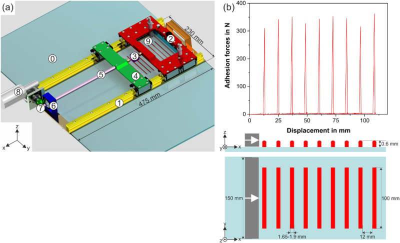
Contact angle measurements
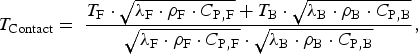
Contact angle measurements were performed with a Krüss DSA100 (Krüss GmbH, Hamburg, Germany) at different temperatures. Prior to the surface analysis, ABS and PLA were pressed to plates (160 × 160 × 2 mm3) in a Collin P200PV vacuum press (Dr. Collin GmbH, Germany) at 200°C for PLA and 270°C for ABS, and 150 bar for 25 min. As printing beds, the glass mirror and the PI film were investigated. The resulting contact angle between each material and the test-liquids 1-Bromonaphthalene (CAS 90-11-9) and Ethylene carbonate (CAS 96-49-1) was measured. Fifteen repetitions were performed per combination, in which the propagation of uncertainty was considered. In all graphs, the corresponding error is displayed. The results were evaluated as described in [8, 9]. For the contact angle measurements at higher temperatures, the contact temperature between the printing die and the printing bed was calculated as:
Microscopy
The contact surfaces of selected printed strands were analysed in the optical microscope Olympus BX51 (Olympus Life Science Europe GmbH, Germany) at a magnification of 50× under reflected light. The specimens were used after testing their adhesion forces (section ‘Adhesion measurement’) without further modification.
Results
Adhesion forces
The adhesion forces for both PLA (Figure 2(a)) and ABS (Figure 2(b)) show a strong dependence on the printing bed temperature. In the case of PLA printed on both bed materials (Figure 2(a)), up to a bed temperature of 60°C a steady rise in the adhesion force is observed. This increase can be attributed to an enhanced chain mobility of the deposited filament with higher temperatures [10, 11]. A point to highlight is the strong increase in the adhesion force as the temperature of the printed bed augments from 60 to 70°C. For PLA printed on PI the adhesion forces rise from 51 ± 8 to 322 ± 47 N, whereas the measured forces on glass are enhanced even more, from 73 ± 19 to 651 ± 17 N. This is related to the glass transition temperature (TG) of the printing material (60.6°C for PLA). Around the TG, the segmental mobility of macromolecules is the highest for a material, which might result in enhanced adhesion between polymeric surfaces and other materials [10, 12]. When the segmental mobility is increased, segments of the polymer chains can diffuse into the interface and the amount of adhesion is dependent on the extent of interdiffusion and chain interpenetration into the interface [13].
Adhesion forces as a function of printing bed temperature and bed material (glass or PI) for PLA (a) and ABS (b). The TGs of the filament materials are depicted as the blue lines.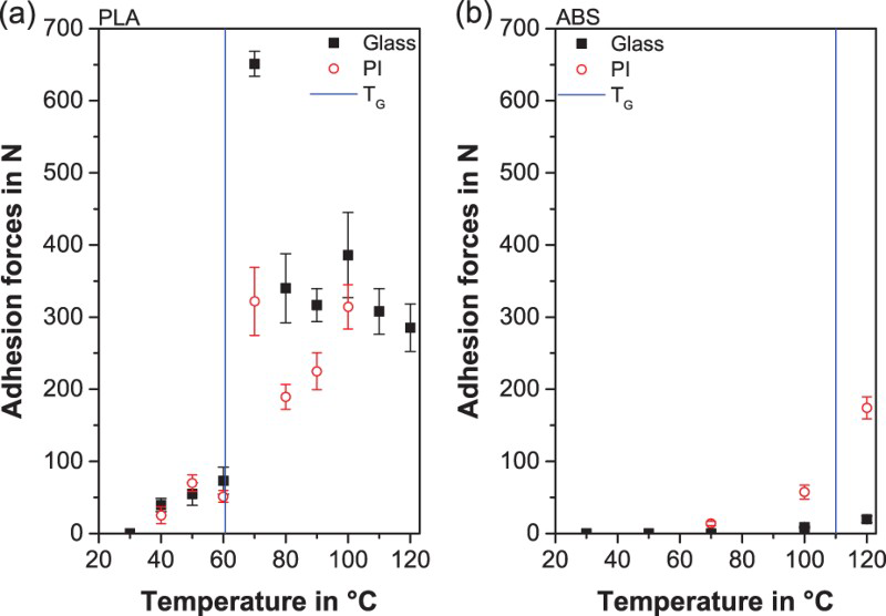
As the temperature keeps increasing beyond 70°C, the adhesion forces drop independent of the printing bed material to roughly 50–60% of the forces for a bed temperature of 70°C. The described decrease can be attributed to the changed interaction between the molten polymer and the printing surface. A higher negative Laplace pressure is generated, which drags a large amount of polymer to some parts of the interface, while other parts are underfilled. Such changes in pressure can lead to what is referred as fingering or Saffman–Taylor instabilities, which are wavy undulations at the periphery of the contact area that can decrease the adhesion force [14]. For the PLA printed onto the glass, the adhesion forces reach a plateau after 80°C. For the PI film, the behaviour is more complex, since the PI is also a polymeric material and its segment mobility increases with temperature [15]. Therefore, a continuous increase in the adhesion force is observed as the temperature increases from 80 to 100°C. Measurements beyond 100°C were not possible, because the adhesive used to glue the PI film onto the glass failed at these high temperatures and measured forces.
The adhesion behaviour of ABS printed onto the glass or PI film exhibits a similar trend to that of PLA. The adhesion forces increase with rising temperature in a non-linear fashion with a maximum slightly above the TG. As it was not possible to measure at temperatures higher than 120°C due to limitations of the printer bed heaters, a peak could not be observed in the adhesion force diagram for ABS. However, it is expected that there would be a peak after the TG, since this behaviour was also observed for other amorphous polymers such as poly(methyl methacrylate) [14]. The adhesion between ABS and PI is much better than that of ABS and the glass, due to closer similarities of the polar and disperse fractions of the two materials, expressed by the lower interfacial tensions, which is shown in section ‘Contact angle measurements’. When comparing the adhesion force values for PLA and ABS, it can be clearly seen that those obtained by ABS are significantly lower than those of PLA. However, both materials could be printed without the risk of detaching from the printing bed. For large-area parts, the warpage needs to be considered, as it counteracts the adhesion due to uneven shrinkage of the printed layers that tend to pull the part away from the printing surface [16]. From the authors’ experience, adhesion forces of at least 200 N, as obtained from adhesion measurements on strands by means of the shear-off testing device, are sufficient for larger parts to hold them in place during printing. Hence, for ABS a bed temperature of at least 120°C (T > TG) and the bed material PI are necessary to ensure proper adhesion during printing, whereas for PLA bed temperatures higher than 60°C (T > TG) independently of the bed material are more than sufficient for a successful printing. On the contrary, for very high adhesion forces, such as occur e.g. for PLA and glass at 70°C, a second issue has to be considered. Too high adhesion forces can lead to a damage of the printing bed during cooling. Therefore, in fact, the optimal printing bed temperature has to be carefully selected within a moderate adhesion force range. For PLA and glass, for example, printing bed temperatures between 80 and 120°C can be recommended.
As can be seen from Figure 2, for PLA a temperature close to room temperature can be recommended for a damage-free removal after printing for both surface materials, as the adhesion force is close to zero at this temperature. However, for ABS the adhesion to PI and glass is negligible already at 50°C. Hence, the finished parts can be easily removed also at a slightly elevated temperature.
Contact angle measurements
The adhesion force is dependent on the compatibility between the two surfaces [13], which is affected by the polarity and the thermodynamic characteristics of the two interacting surfaces. One way to determine the compatibility between surfaces is to calculate the interfacial tension from contact angle measurements [17]. The adhesion between two contact materials is inversely proportional to the interfacial tension values, and such values are inversely dependent on the surface energies and polarities of the materials in contact [9].
Figure 3 compares the interfacial tension to the measured adhesion force at two temperatures for both printing materials and printing beds. The selected temperatures are 10 K below and above the TG of each printed material. Despite the big variations, a trend towards decreased interfacial tensions for increasing temperatures can be seen for both PLA and ABS (Figure 3(a,c)). This trend is in accordance with the adhesion force results (Figure 3(b,d)), in which a drastic increase is observed for higher temperatures. Moreover, the trend towards higher adhesion forces for printing PLA on the glass than on the PI surface is reflected by the interfacial tension values (Figure 3(a)). Also for ABS, the interfacial tension results (Figure 3(c)) reflect the trend of the adhesion measurements (Figure 3(d)), in which the adhesion on the glass is inferior to that on the PI film. However, the overall trend in the contact angle measurements (Figure 3(a,c)) does not reflect the significant difference in the adhesion forces (Figure 3(b,d)), but the contact angle measurements rather exhibit non-significant differences in the interfacial tension. Hence, the adhesion mechanism cannot be solely explained by surface chemical analyses, such as contact angle measurements.
Interfacial tension obtained from contact angle measurements as a function of printing bed temperatures for PLA (a) and ABS (c) compared to adhesion forces of PLA (b) and ABS (d) at the same temperatures.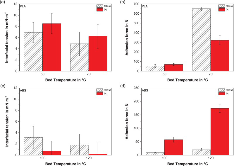
Microscopy analysis
The adhesion of polymers onto different surfaces is additionally affected by the surface topology and the impurities that may be present on the surface [18]. The magnified surfaces of the printed parts after being sheared-off at different temperatures as well as one representative force–displacement curve each are shown in Figure 4 exemplarily for PLA. Similar results are expected for ABS and hence they were not included in this manuscript. It can be seen that the temperature does indeed have an effect on the resulting topology of the printed parts.
Optical microscopy images of printed PLA parts after being sheared-off from different surfaces at different temperatures: (a) glass at 50°C, (b) glass at 70°C, (c) PI at 50°C and (d) PI at 70°C. In the top right corner of each image the corresponding adhesion force is shown. In the bottom left corner of each image one representative force–displacement diagram with the same displacement labelling is shown to visualise the difference in their shear failure. The circles highlight sheared-off pieces of the printing bed and the arrows the loading direction of the measuring device.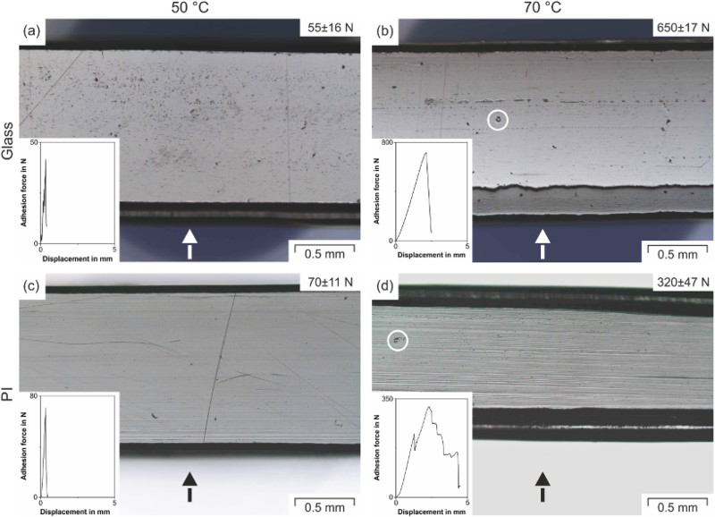
PLA printed on the glass at 50°C (Figure 4(a)) shows some voids on the surface, whereas the part printed at 70°C (Figure 4(b)) has a slightly smoother surface. The higher amount of voids reduces the effective contact area, resulting in adhesion forces of only 55 ± 16 N. On the other hand, the smoother surface obtained by printing on the glass at 70°C indicates a better contact between the PLA and the glass. Due to the increased diffusion of the polymer onto the glass and the reduced interfacial tension, this leads to a higher adhesion force of 650 ± 17 N and to a considerably broader adhesion force peak as can be seen in the insert in Figure 4(b). Another indication for the strong adhesion of the specimen printed at 70°C (Figure 4(b)) is the deformation of the first layer, displayed in the bottom of Figure 4(b). This originates from the local bending due to its strong adhesion and the shearing block. The white circles, highlighted in Figure 4(b), represent the presence of pieces of glass that had been sheared-off from the glass during the adhesion force measurements. This finding confirms that extreme adhesion between the printed part and the printing bed might not be favourable, since it can destroy both material in contact, as discussed in section ‘Adhesion forces’.
When the surfaces of printed PLA on the PI film are compared to those on the glass, an opposite trend is observed: The smoother surface of the specimen printed at 50°C (Figure 4(c)) has a lower adhesion force (70 ± 11 N) than that of the specimen printed at 70°C (Figure 4(d)) (320 ± 47 N). However, when printing on PI, the rougher surface does not exhibit voids, but rather channels oriented parallel to the length of the printed part.
The different behaviour of the specimens printed on PI might be related to the fact that the PI is indeed a foil, which is in turn glued on another printing bed layer, while the glass is itself a rigid plate. At high temperatures, when the adhesion force between PLA and PI is high, it can be speculated that the interface between the PI foil and the lower printing bed layer can pose a weak link. As can be seen in Figure 4(d), the PI foil is not torn off in the course of the shearing experiments, indeed it is not damaged. The shearing, which in the case of the PI foil does not take place as a uniform motion and thus causes the channels, can also be correlated with the force–displacement curve (insert Figure 4(d)), which does not exhibit one peak, but several local maxima and inflexion points.
These channels can increase the contact area between the deposited filament and the flexible PI film. Thus, the surface favours more diffusion of the PLA molecular segments, leading to higher adhesion forces. Also for the surface represented in Figure 4(d), the local deformation in the bottom of the illustration is observed and a piece of the bed surface is sheared-off during the measurement (highlighted by a white circle).
Conclusion
We present here a systematic study on the effect of the printing bed temperature on the adhesion of parts printed by FFF by means of an in-house developed adhesion measuring device. It was observed exemplarily for PLA and ABS that the optimal adhesion of the printed sample to the printing bed can be achieved by heating the printing bed at temperatures slightly above the TG of the filament material. Increasing the temperature above the filament's TG leads to a reduction of the surface tension between the printing bed and the printing material and to a larger contact area that ultimately causes better adhesion between the bed and the filament. We believe that the process presented in this study is readily applicable to other thermoplastic polymers with a TG above room temperature. Our findings provide the first steps for finding optimal printing bed temperatures for novel material compounds.
Footnotes
Acknowledgements
Special thanks go to Petra Erdely for fruitful discussions, Philipp Huber for the construction of the adhesion device and Florian Arbeiter, Gerald Berger, Radoslav Guran and Christof Lichal for their help with the measurements.
Disclosure statement
No potential conflict of interest was reported by the authors.