
Abstract
Creep-resistant nickel, cobalt based superalloys, selected for a high-speed flight application, deposited using Wire + Arc Additive Manufacturing (WAAM), was reported. Three different alloys, Haynes 188, Inconel 718, and Rene 41, were deposited, and tested for their high-temperature tensile properties, and the results compared with wrought data. The alloys were tested from ambient temperature to 1000°C in their as-deposited condition and after undergoing industry standard age-hardening and solutionising heat-treatments, to down select the best performing alloy under two different processing conditions. The mechanical strength of the alloys fell short of the maximum achievable in wrought condition. Precipitation-strengthened alloys, Inconel 718 and Rene 41 were found to have underperformed the most significantly, whereas solid-solution-strengthened Haynes 188 suffered the least due to WAAM.
Keywords
Introduction
Wire + Arc Additive Manufacturing (WAAM) which has been continually developing since the 1990s, is defined by Williams et al. as the combination of an electric arc as a heat source and wire as a feedstock [1]. WAAM utilises traditional welding technologies such as TIG/MIG welding [2], however, WAAM also combines arc welding technologies with a motion control system, to deposit material from wire feedstock in a layer-by-layer manner [3]. WAAM is capable of depositing a near net-shape product [4], which differentiates it from other additive manufacturing methods. WAAM components are often subject to further processing as necessary to achieve a final component.
WAAM has several benefits over other manufacturing methods such as machining. Compared to machining, the near-net shape WAAM process reduces the waste material and lead time and as a result also cost [4,5].
Superalloys are defined as ‘a group of nickel-, iron-nickel-, and cobalt-base materials that are used at temperatures of 540°C and above’ [6] – note that superalloys are not exclusively used above 540°C. Originally the development of superalloys centred on their application in superchargers for aircraft piston engines. More recent nickel alloy development however has been for applications in gas turbines. Nickel superalloys are currently in service in a variety of applications including gas turbines from aerospace to, oil and gas, chemical plants and in nuclear applications [7]. It is not uncommon for nickel superalloys to experience operating temperatures of between 150 and 1500°C.
The effect WAAM has on creep resistant superalloys is mostly unknown, specifically high-temperature material properties which is important for high-speed flight applications. Nickel-based superalloys have excellent performance at elevated temperatures which makes them useful for the production of components for high-speed flight using WAAM.
Previous studies of high-temperature metals that have been deposited using WAAM include Ti–6Al–4 V [8], high-purity tungsten and other refractory metals [9]. At Cranfield University the following alloys have been deposited using WAAM:
Nickel alloys: Inconel 625, Inconel 718 Refractories: tungsten, molybdenum, tantalum Titanium: grade 2, grade 5, grade 5 with O2 doping, grade 23, 5553, Timetal 407 [10].
In this research, Inconel 718 (IN718), Rene 41 (RE41) and Haynes alloy 188 (H188), are deposited using a plasma transferred arc WAAM process. A comparison of the mechanical properties of these three WAAM built alloys was carried out at ambient and elevated temperatures, in as deposited and their standard recommended heat-treated condition. Following this the suitability of these WAAM built alloys for high-speed flight was discussed. The study shown here is a continuation on the previous work of James et al. into the room-temperature properties of the same alloys [11–13].
The aim of this study is to understand the performance difference between the alloys in wrought condition and the WAAM alloys, as well as optimising the mechanical properties for a high-speed flight application, where external structures could reach service temperatures as high as 1000 K (727°C) and 1200+ K (927°C) for components in the propulsion flow path. To minimise the structural mass of components in this single use system, components will be highly stressed. The ideal outcome of this research will be to achieve in WAAM built material similar properties as wrought IN718 or better. Being focused on very good short-term high-temperature properties, the alloys investigated in this project were subjected to high-temperature testing from room temperature up to 1000°C.
Physical Metallurgy of H188, IN718 and RE41
The physical metallurgy and superalloy phases are dependent on composition. An austenitic face-centred cubic (fcc) phase, γ, is present in most superalloys as well as various secondary phases. Secondary phases such as carbides can consist of MC, M6C, M23C6 and M7C3, where ‘M’ represents the metallic element. Intermetallic compounds can also be found in most alloys as secondary phases, which commonly include: γ′ fcc phase Ni3(Al,Ti), γ″ body-centred tetragonal (bct) phase Ni3Nb, η hexagonal ordered phase Ni3Ti, and δ phase orthorhombic Ni3Nb. Detrimental phases can also be precipitate in superalloys, which are capable of damaging performance if present in larger amounts. Typical detrimental phases in superalloys include topologically close-packed (tcp) phases: µ Co2W6/(Fe,Co)7(Mo,W)6, Laves phase A2B type where ‘A’ and ‘B’ represent metallic elements, and σ which can include more complex intermetallic phases [13,14]. Tcp phases are often detrimental to performance as they tend to be very hard, and if present as plate-like morphology or as grain boundary films can lead to cracking. Additionally, tcp phases can deplete elements such as Cr and Mo which can reduce the alloys corrosion resistance [15].
The metallurgy of the three superalloys is different and each alloy has a unique strengthening mechanism. RE41 and IN718 are somewhat similar in composition both being Ni based, H188 is the odd one out in this study as it is predominantly Co based, however, is alloyed significantly with Ni and Cr.
Haynes 188
Co based H188 is strengthened in a significantly different way than the other two Ni-based alloys. It is not hardenable except through cold working, and its strength is derived from its solid-solution-strengthened fcc matrix. It has a primary carbide M6C associated with a La rich compound, when aged at 760°C for 200 hrs a secondary carbide M23C6 is known to form at the grain boundaries with A2B type Laves phase Co2W and causes increased hardness and reduced ductility. Longer term exposure to temperatures between 760–870°C can precipitate enough Laves to embrittle the alloy [16]. γ′ and γ″ phases are possible to see in Co-based alloys containing Mo and Ta [17] but as these are not present in H188 they are not observed.
Inconel 718
IN718 is an age hardened Ni-based superalloy, with an austenitic fcc matrix. The primary strengthening phases are γ′ Ni3(Al,Ti) L12 structure and γ″ Ni3Nb bcc D022 structure. Undesirable phases that can form in the alloy include Laves and δ phases. Laves phases take the form of A2B type (Ni,Cr,Fe)2(Nb,Mo,Ti) and can form due to variation in composition, processing and high-temperature exposure, formation of Laves is known to deplete Nb required for γ″ formation [18,19]. Carbides formable in IN718 is primarily MC type (Nb,Ti)C, M6C can also form at the grain boundaries with longer exposure to temperature [20].
Rene 41
RE41 is an age hardened Ni-based superalloy with a fcc austenitic matrix, RE41 also contains Co and Mo differing it from IN718. The main strengthening phase is γ′ Ni3(Al,Ti) [21]. Ni3Al, and Ni3Ti form fine uniform particles at 760°C and are coarser at higher temperatures. Ni3Ti appears fine below 760°C and acicular above 760°C. Ni3Al appears coarse and curved and is seen in larger amounts at grain boundaries. δ phases are not seen generally due to Cr and Mo being tied up in the carbides. Laves phase can form where C is less than 0.05% and Al less than 1% at 815°C [13,22]. The main carbides are M6C (Mo,Co)6C and/or M23C6 (Cr23C6), which form at higher temperatures due to higher Mo and W content [23–25].
Method
Deposition of Rene 41 and Haynes 188
The following alloys, RE41 and H188, were deposited using the same WAAM system, which consisting of a plasma power source, a FANUC six-axis robot, a water-cooled plasma welding torch mounted to the robot, an external wire feeder, and a part rotator – allowing for symmetrical WAAM wall building. The complete robot set-up and work piece was housed inside a tented enclosure, which was filled with Ar during the WAAM process at an oxygen level controlled below 800 ppm, which was monitored using an oxygen analyser. The experimental set-up is shown in Figure 1, and process parameters were kept consistent with a previous study on the same alloys by James et al. [11,12]
Experimental set-up used to deposit RE41 and H188.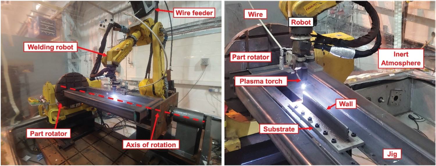
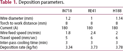
Deposition parameters.
A symmetrical wall building process was used to deposit both RE41 and H188, this process involves depositing two wall structures simultaneously on both sides of the substrate plate. Using a part rotator material is deposited alternately between both sides of the substrate. The main advantage of this process over a single-sided operation is the reduction in warping of the substrate and residual stresses as this is ultimately cancelled out when an identical structure is built on both sides [1]. Productivity is also increased, as cooling can partly take place on one side when the WAAM process is continuing on the opposite side, which reduces the system idle time.
Deposition of Inconel 718
For IN718, a WAAM system consisting of:, a Migatronic 320A AC/DC plasma power source, a three-axis linear CNC system, a water-cooled plasma torch mounted to an adjustable jig on the CNC system, an external wire feeder and a glove box filled with Ar at an oxygen level controlled below 800 ppm, as in the previous section, was used for the deposition of wall structures.
The linear wall building process used for IN718 was a single-sided operation where layers were the wall was deposited in a single direction on just one side of the substrate, which is due to system limitations. The same process was used by James et al in a previous study Figrue 2 [12].
Experimental set-up used to deposit IN718 [12].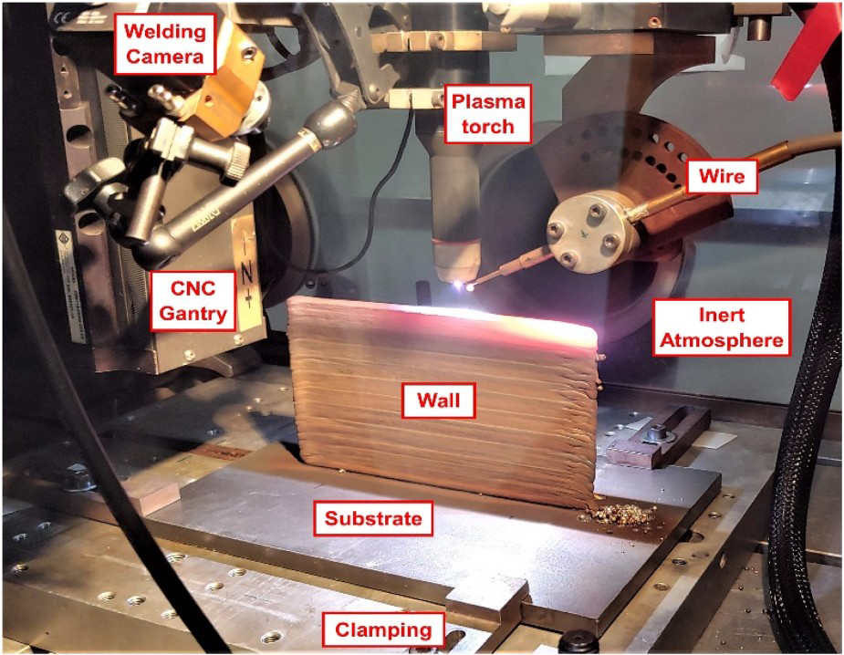
Post-deposition heat-treatments
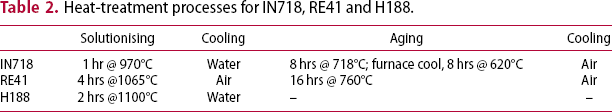
Heat-treatment processes for IN718, RE41 and H188.
Metallographic preparation and analysis
In the H188, RE41 and IN718 alloys, WAAM walls of 128, 147, and 226 layers respectively were built, note that the difference in the number of built layers is due to the slight variation in deposition rate, which is presented in Table 1. After deposition, the wall structures were cut from the substrate plates. Cross-sections of material were prepared for metallographic analysis by mounting and successively grinding, polishing, and etching. Samples were etched using the following methods to reveal the microstructure:
H188
5 g oxalic acid, 95 ml HCl. Electrolytic 6 V DC using a carbon cathode and stainless anode probe, for 1–2 sec [26].
RE41
3 g CuSO4, 80 ml HCl, 20 ml absolute alcohol. Samples were then immersed in ammonium peroxydisulfate H2O solution weight ratio of 1:20 for 2–3 mins to remove corrosion products [27].
IN718
Kalling's No.2 Reagent (2% CuCl2 in acidified alcoholic base) swab etch for 10 sec.
The microstructure was analysed optically using a Leica DM 2700M Microscope, and under scanning electon microscopy (SEM) using a Tescan VEGA 3 SEM. To compositional analysis the VEGA 3 SEM was equipped with an Oxford Instruments X-Max 20 mm energy-dispersive spectrometry (EDS) detector.
Mechanical testing methods
The microhardness was measured using a Zwick/Roell hardness tester under a load of 500 g and holding time of 15 s. To obtain comparative results for the hardening effect of the WAAM process, unused welding filler wire also underwent a similar process.
In addition to hardness, all alloys also underwent extensive tensile testing at a range of temperatures. Temperatures were selected to be compared against existing data from Donachie's superalloys technical guide [28], an extra test at 1000°C was also carried out to extend the understanding of the alloy performance for the high-speed flight application. Three samples from each alloy were tested in each category and in both as deposited WAAM condition and after undergoing a post-deposition heat-treatment. Tensile specimens were tested at RT, and at elevated temperatures including 538, 760, and 1000°C.
RT and elevated temperature tensile tests (538–1000°C) were carried out using an Instron 8801 Servo-hydraulic Universal Testing System and tested to the ASTM E8M specification for RT testing and E21 for the elevated temperature tests, using a strain rate of 0.005 min−1 until the onset of plastic deformation and thereafter a crosshead speed of 1.6 mm/min, following the method previously used by James et al. [13]. The coupon shown in Figure S-1 was used for RT testing and Figure S-2 shows the coupon used for elevated temperature testing. The location of extracted specimens in reference to the deposited WAAM walls can be found in Figure S-3. Fracture surfaces of the specimens were carefully preserved and observed after testing.
Results and discussion
Macrostructure
All three alloys exhibit a structure which is typical of directed energy deposition. The microstructure is formed of a solidified dendritic structure of large columnar grains, which extend along the height of the wall in the direction from bottom to top, this structure has been observed previously in IN718, IN625 [12], RE41 and H188 by James et al. [11] The structure of IN718 can also be found in the work of Xu et al. [19].
Microstructure
Microstructural features were observed both optically and using SEM. The grain morphology was compared between the three alloys to understand the structure. Similar grain boundary locations in both the as deposited and heat-treated conditions are presented in Figure S-4. The observed structures are similar in appearance with a directionally solidified grain structured consisting of long dendrites extending through the height of the samples in the BD axis, which was also observed by James et al [13]. A thicker dendritic structure and grain boundaries are seen in heat-treated samples.
EDS analysis of areas marked in Figure 3 (%at).
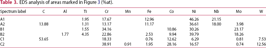
In heat-treated samples of RE41 (Figure S-5 – image B2), chain-like precipitates surrounded by a darker background can be observed at the grain boundaries, larger grey and white precipitates are more evenly distributed within the matrix. The chain-like precipitates seen at the grain boundary are thought to be M6C or M23C6, while the grain boundaries are thought to be darkened in heat-treated condition due to formation of γ’. The larger bright precipitates in the matrix are thought to be a complex intermetallic phase, likely Ni2Mo Laves phase, which is supported by spectrum B2 in Table 3 [13].
Heat-treatment in H188 (Figure S-5 – image C2), had a clear darkening and thickening effect surrounding precipitates at the grain boundaries and within the matrix compared to as-deposited material (image C1). The smaller grain boundary precipitates are thought to be M23C6, whereas elsewhere in the matrix brighter coloured precipitates are thought to be Laves Co2W intermetallic phase and M6C carbides, which would be supported by spectrum C1 and C2 in Table 3. It is also noted that potential M6C carbides seen outside of the grain boundaries are surrounded by smaller darker phases which could be indicative of primary M6C decomposing in secondary M23C6. In some cases (seen in Figure S-6) areas where M23C6 is observed forming a ring, presumably around what was previously M6C carbides which has decomposed, leaving only the secondary carbide remaining. To confirm the presence of specific carbides, an analysis of the phases would ideally be conducted using transmission electron microscopy (TEM) – EDS.
IN718 was observed under SEM and a grain boundary location can be seen in Figure S-7. Substantial segregation of Nb and Mo at the grain boundary can be seen in the AD structure, as seen in Figure S-8, where the elemental map shows strong segregation of Mo and Nb, where Cr and Fe has been displaced, also seen in the map are very small areas of Ti rich zones indicating potential Ti rich carbides. Similar features were seen across the other alloys Figure 3.
BSE images of microstructure of IN718 (A), RE41 (B), H188 (C), as deposited (1), heat-treated (2). Seen in the TT and BD axes.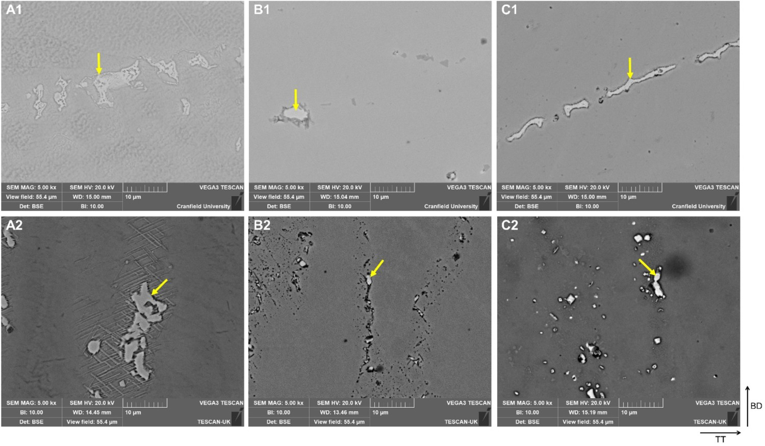
Mechanical performance
The performance of all alloys in their as deposited and heat-treated condition is shown in Table S-2, where the experimental data is shown with wrought data from literature for comparison; note that data for 1000°C is often not available in the literature.
Graphs comparing the performance of the alloys for the complete range of temperatures is shown in Figure 4. The best overall performance, as anticipated from the literature, is RE41 followed by IN718 and H188. In RE41 and also in IN718, as-deposited performance was seen to increase at the 760°C test compared to the 538°C performance, the same phenomenon was previously seen by James et al in RE41 [13]. The worse performing alloy compared with maximum stated values from literature is as-dep IN718 which achieved on average 47.8% of the maximum values, followed by RE41 58.8% and the closest performance H188 achieving 63.7% of the stated maximum. When heat-treated the performance increases to an average of 62.5, 61.4 and 72.8% for IN718, RE41 and H188 respectively. Results between RE41 and IN718 are largely similar until 760°C, where the difference in YS performance is more apparent, with RE41 performing better at this temperature.
Comparison of mechanical testing data and wrought data.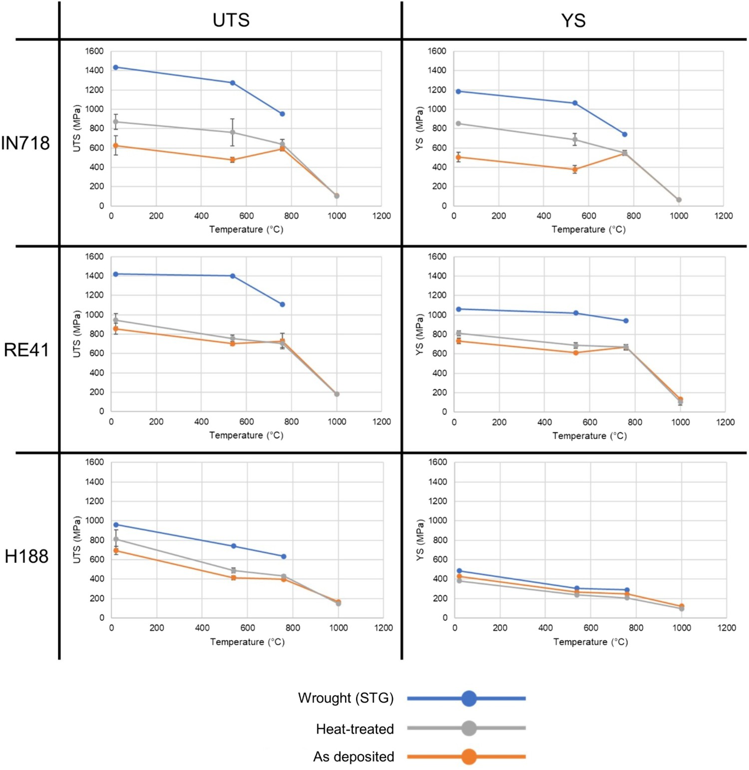
The mechanical performance is each alloy is largely reflective of the microstructure. For example, a significant amount of cracking was seen in IN718, due to the formation of complex intermetallic phases at grain boundaries, which is also true to a lesser extent for RE41. Over aging of the precipitation hardenable alloys is likely to be responsible for this, with IN718 being the most hardenable alloy, the effect of over aging had the biggest impact. All the alloys were formed of large columnar grains, as per the WAAM process, which also affected their performance against the wrought strength.
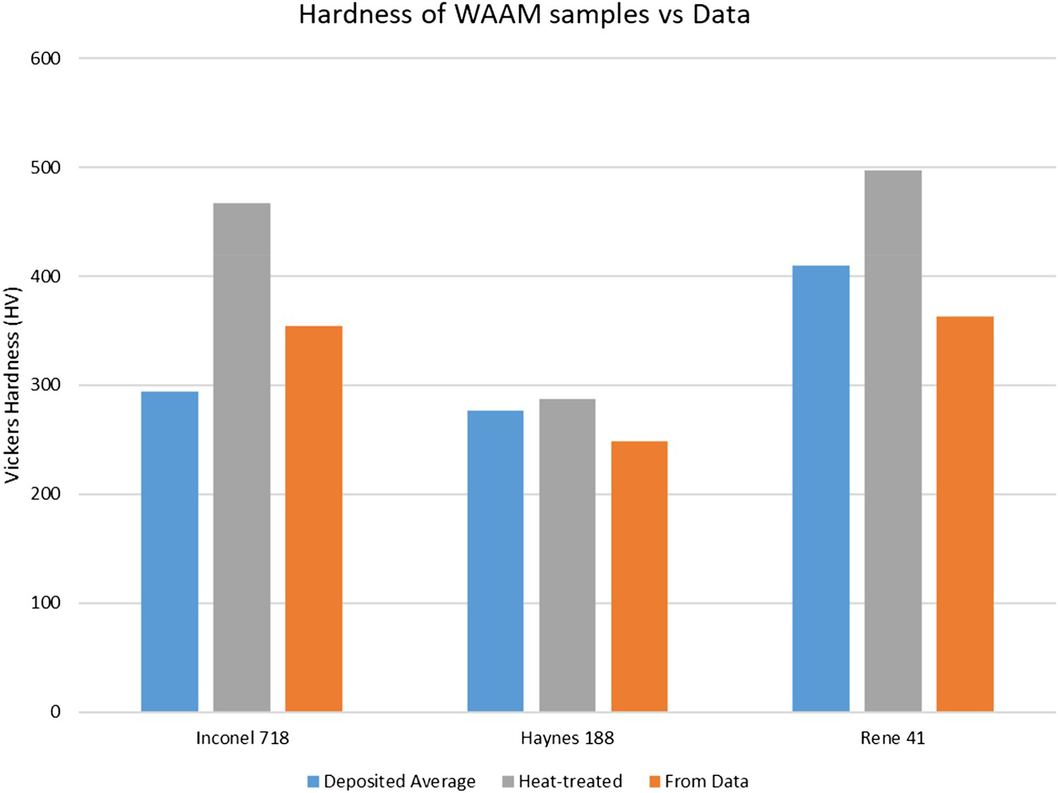
Microhardness
The hardness data presented in Figure 5 shows a correlation between the WAAM material and the wrought data. With the exception of IN718, the WAAM process is shown to increase the hardness of deposited alloys over wrought values, as deposited H188 and RE41 increases in hardness by 11.4 and 13.0% respectively. IN718's as-deposited hardness is shown to be less than the wrought value and this is thought to be due to the extensive ageing process that this alloy typically undergoes to achieve peak performance. When heat-treated the hardness values is significantly higher than both the as deposited value and the wrought data, compared to the wrought value heat-treated IN718 is 31.9% harder. A similar situation exists for RE41, when heat-treated the material is 36.8% harder than the wrought material. The hardening effect is also seen in H188 but to a lesser extent than the other alloys, this is thought to be due to H188 not being an age hardenable alloy and as such only underwent a solutionising treatment; heat-treated H188 is only 15.9% harder than the wrought value. The hardness values for all alloys in each condition are compared with the wrought value in Table S-3.
Fracture surfaces
In the macrographs (Figure S-9 and S-10) most of the fracture surfaces have a fibrous appearance, indicating a complex load metal interaction and crack propagation under mixed tensile and shear modes perpendicular to the loading axis. Fracture surfaces showed crack propagation on an inclined plane suggesting failure by shearing. From Table S-2, it can be concluded that in wrought and HT condition, the overall elongation is much higher which could be attributed to the fact that the grain structure in a wrought alloy would be more refined with high angle grain boundaries while additive built structures have a dendritic grain structure with significant directionality in grain orientation. Another aspect which might have resulted in a reduction in toughness would be the presence of defects in the WAAM built structure, which would result in a lowering of toughness. The large angle grain boundaries in a wrought alloy would also favour diffusion and as a result the strengthening response of the age hardenable alloys are better when compared to additive built structures.
The fibrous appearance of fractures suggests they are intergranular, this can be most clearly seen in Figure S-10, image A1, in which what appears to be a whole section of grains has been dislodged during fracture. The cheveron patterns seen across several specimens (seen clearly in Figure S-10, images B1 and C1), are likely to be slip steps, though striations which occur microscopically are similar in appearance. These patterns which appear on predominantly on RT, 538°C can be indicative of rapid fractures associated with more brittle behaviour [31].
A very different fracture behaviour is observed for specimens tested at 1000°C. fractures appear very much ductile, and cross-sections appear distorted. Separation between grains is also observed in specimens of IN718 and RE41. Samples in H188 show obvious slip steps at this temperature and large cracking was seen throughout the samples at this temperature. One sample, seen in Figure S-9, image A4, can be seen to have cracked almost along the entire length of the specimen, a feature that reaches the surface on this sample would suggest a welding imperfection perhaps introduced by an inclusion, an additional view is given in Figure S-11. At 760°C IN718 and RE41 fracture surfaces appear more irregular displaying uneven crack propagation path compared to H188. A slight colour difference is also observed at this testing temperature, which could suggest oxide scale formation due to testing not occurring in an inert environment.
With increased testing temperature grain boundary appear to thicken (Figure S-12), this is most clearly seen in the samples of IN718 and RE41 tested at 1000°C (Images A4 and B4 in Figure S-12), the difference is less pronounced in H188. This difference is likely to be due to the precipitation of secondary phases which reflects the aging characteristics of the alloys, IN718 is the most age hardenable whereas H188 is not age hardenable. A comparison between heat-treated RE41 and as deposited samples tested at temperature is shown in Figure S-13, where the microstructure directly behind the fracture surface is shown. It can be clearly seen that the grain boundaries are even more pronounced in the heat-treated variant, increasing with testing temperature.
When looking at the grain boundaries of RE41 1000°C tested specimens under SEM, what looks to be δ phase precipitates can be observed (B in Figure S-14). Using EDS to analysis this area (Table S-4) they appear however to be entrapped oxide. Which separates them from potential Laves phases in area A which is Mo rich. Similar features were also observed by James et al in RE41 [13].
Conclusion
As deposited WAAM alloys IN718, RE41 and H188 achieved 47.8, 58.8 and 63.7% respectively of their maximum stated performance, and using a heat treatment specific to the alloys results in a performance increase to 62.5, 61.4 and 72.8% of max. performance respectively. The WAAM process increases hardness in alloys RE41 and H188, by 11.4 and 13%, and is seen to partly age all alloys. Performance of as deposited alloys IN718 and RE41 at 760°C increases to largely meet the performance of pre-heat-treated specimens, indicating an in-test aging process. Performance largely drops off at a 1000°C testing temperature (except for H188 which remains relatively stable). Which is potentially due to precipitation of undesirable oxide phases at the grain boundaries. Precipitation of complex intermetallic phases was found at the grain boundaries in all alloys and at crack edges in IN718 and RE41, indicating an embrittling effect leading to intergranular cracking. RE41 is the best performing alloy for the high-speed flight application.
Footnotes
Acknowledgements
The authors wish to acknowledge the UK Ministry of Defence for their financial support, and the industrial supervisors from DSTL Porton Down, for their ongoing advice and guidance: Graham Simpson and Dr Matthew Lunt. The authors would also like to acknowledge the technical assistance from Dr Tracey Roberts, Steve Pope, and Kristopher Bramley during imaging.
Disclosure statement
No potential conflict of interest was reported by the author(s).
Statements and declarations
The datasets generated and analysed during the current study are not publicly available as they are the subject of an ongoing study but are available from the corresponding author on reasonable request.
In the author's opinion there are no ethical issues with the research presented in this paper. The authors confirm this manuscript has not been published elsewhere and is not under consideration by another journal.
All authors consent to the publication of this paper.