
Abstract
A new low transformation temperature (LTT) welding material 16Cr8Ni was developed to satisfy the optimal characteristics in diluted welds due to all repair welding positions. Its good weldability for all welding positions was tested. The measured Ms temperature of weld metals with different dilutions was between 150°C and 250°C which is the optimal range for compressive residual stress generation and fatigue life extension. The in-situ observation of phase evolution by the synchrotron-based X-ray diffraction technique validated the solidification mode of LTT welds for the prevention of solidification cracks. Moreover, the mechanical properties in the diluted LTT welds were measured by miniature uniaxial tensile tests. Large compressive residual stresses at the welded joints due to all welding positions were confirmed numerical analyses.
Keywords
Introduction
The arc welding usually induces the non-uniform temperature distribution and tensile residual stress in weld metals. Generally, the tensile residual stress is detrimental to the fatigue performance [1], cold cracking [2] and stress corrosion cracking [3]. To reduce the tensile residual stress, shot peening, ultrasonic peening and post-weld heat treatment can be employed [4]. Unfortunately, these methods belong to post-weld treatment, which can be time-consuming, uneconomical and unsuitable for large-scale complex welded structures.
With the development of materials science, researchers discovered that the residual stress can be adjusted by the phase transformation. The first fundamental study was conducted by Bühler and Scheil [5] focusing on the effect of the martensite start (Ms) temperature on the residual stress. They showed that the thermal shrinkage and volume expansion of martensitic transformation played a significant role in the magnitude of residual stress. Jones and Alberry [6] revealed that the transformation strain induced from austenite to bainite/martensite offsets the thermal strain during cooling. The compressive stress was generated during the bainitic or martensitic transformation process, while the tensile residual stress was finally produced because it is accumulated one during the full cooling from solidification temperature to phase transformation start temperature and then to room temperature.
Following previous studies, Murata et al. [7] developed an iron-based alloy by adding 10% chromium and nickel (10Cr10Ni) and measured its Ms temperature of approximately 180°C. Owing to the lower Ms temperature, this type of iron-based alloy is called as low transformation temperature (LTT) welding material. The 10Cr10Ni LTT welding material can produce compressive residual stress in weld metals [8]. Then, investigations on LTT welding materials were extended to fatigue performance.
Francis et al. [9] indicated that decreasing the Ms temperature from 460°C to 280°C reduced the tensile residual stress gradually and even produced compressive residual stress in the LTT weld. Murakawa et al. [10] employed finite element method (FEM) to clarify the effect of transformation temperature range on residual stress. They found that the compressive residual stress was produced when the Ms temperature was less than 400°C. Furthermore, the compressive residual stress increased when the Ms temperature decreased down to 200°C, while a further reduction in the Ms temperature had no additional benefit [10]. Feng et al. [11] analysed and measured the residual stress in the multi-pass LTT welded joint, which showed that the compressive residual stress was certainly induced in the final welding pass.
Owing to the generation of compressive residual stress in LTT weld metals, many researchers started the investigation of its contribution to fatigue life of welded joints. Ohta et al. [8] adopted 10Cr10Ni LTT welding wire and doubled the fatigue strength of corner boxing fillet joint of high-strength steel HT780. Darcis et al. [12] reported their results on the fatigue strength of cruciform fillet welded joints using three types of LTT welding wires with Ms temperature in the range 270–360°C. It was found that the fatigue life of LTT welded joints was at least three times longer than that of specimens using conventional welding wire. Miki et al. [13] used the LTT welding material to repair cracked joints and found that the fatigue life of repaired joints was also improved to a certain degree.
Apart from fatigue performance of LTT welded joints, researchers have also made great efforts on improvement of mechanical properties of LTT weld metals, especially the toughness. Zenitani et al. [14] found that the retained austenite was beneficial to cold cracking resistance. Qiu et al. [15] enhanced the fracture toughness of high-strength LTT weld metals via strain-induced martensitic transformation. Wu et al. [16] increased the amount of retained austenite through the addition of more nickel content. Generally, further decrease of the Ms temperature of LTT weld metal is necessary to obtain a large percentage of retained austenite. However, a too low Ms temperature of LTT weld metal renders the residual stress mitigation inefficient. Additionally, the solidification cracking susceptibility increases when the Creq/Nieq ratio becomes smaller. To date, some unsatisfied mechanical properties still restrict the application of LTT welding materials. An often overlooked aspect in the design of LTT consumables is how to combine the desirable low transformation temperature with appropriate weld metal strength, toughness and safety against hot and cold cracking.
To solve this problem, Shiga et al. [17] overlaid the 10Cr10Ni LTT welding metal on conventional fillet welds by the elongated bead with 80%Ar and 20%CO2 shielded gas, which produced a larger compressive residual stress and greatly reduced the stress concentration of welded joint. As a result, the LTT elongated bead greatly improved the fatigue life of corner boxing fillet joint to at least four times without deterioration of fracture toughness. However, the Creq/Nieq ratio of the 10Cr10Ni welding wire is about 0.98 and its solidification cracking susceptibility is worried. On the other hand, the existing LTT welding materials can only be used in the flat welding position and are still impractical to repair welding the fatigue crack produced in ship and bridge structures, especially when using the low-cost CO2 arc welding in different welding positions. Therefore, development of a new LTT welding material available to all five welding positions (overhead, horizontal, vertical-up, vertical-down, flat welding positions) required in repair welding, is essential.
The final goal of our study is to extend the fatigue life of corner boxing joints by LTT elongated bead method. In this paper, the first work is to develop a new LTT welding material considering different dilutions due to all repair welding positions with low-cost CO2 shielded gas and then to propose practical welding sequences suitable to overhead, horizontal, vertical-down and vertical-up welding positions besides traditional flat welding. Secondly, the relationship among dilutions, Ms temperature, microstructure and tensile properties is investigated for LTT weld metals under various dilutions. Third, in-situ observations using synchrotron radiation X-ray diffraction (XRD) were made to identify the solidification mode and confirm the excellent resistance to solidification cracks. Finally, numerical analyses were conducted to confirm the generation of compressive residual stresses due to all welding positions.
Chemical composition design of LTT material and its welding wire development
A new LTT welding wire was developed based on the Fe-Cr-Ni system. According to the results of Feng et al. [18], a higher volume expansion strain more than 0.4% is beneficial to the generation of compressive residual stress. In addition, Hayakawa et al. [19] indicated that a number of weld metals with Ms temperature in the range 100–250°C generally had a volume expansion strain more than 0.4%. Since the chemical compositions of LTT weld metals vary with dilutions, it is paramount to select proper alloy contents and to establish the relationship between the Ms temperature and alloy elements such as Ni, Cr, etc. for LTT weld metals. On the other hand, the susceptibility to solidification cracking generally increases if the austenitic solidification mode (A-mode) occurs in the high alloy metals with the smaller Creq/Nieq ratio such as LTT weld metals. To reduce this susceptibility, it is necessary to design the chemical compositions of LTT weld metal that gets into the composition area of ferritic-austenitic (FA) solidification mode [20]. Based on this concept and author's accumulated experiences, following conditional equations were used to design the new LTT welding material.


From our previous studies of Ms temperature of LTT weld metals with the FA solidification mode using Formaster tests, the relationship between the Ms temperature and chemical compositions can be expressed as:

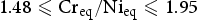
Figure 1 shows the modified Schaeffler's diagram that determines the Ms temperature and FA mode of weld metals estimated by Equations (1) and (2). The chemical compositions of the new LTT weld metals with the dilution range between 10% and 30% denoted by circles Di = 10%, Di = 20% and Di = 30% were studied previously. The orange region in Figure 1 means the LTT weld metals with Ms temperatures varying from 100°C to 250°C. Hence, we designed the 16Cr8Ni alloys denoted by the solid red circle for the LTT welding material, of which the detailed chemical compositions of weld metals are shown in Table 1. Furthermore, the new LTT flux-cored welding wire (FCW) was manufactured by Kobel Steel Ltd. to satisfy the request of all welding positions with 100% CO2 shielding gas and its registered product name is ‘TRUSTARC DW-168FP’. In Table 1, the chemical compositions of base metal KA36 and conventional welding wire MX-Z200 similar to the AWS A5.20 E70T-1C for the fillet weld before overlaying LTT elongated bead, are also listed.
Design of equivalent alloy elements for newly developed LTT welding material. Chemical compositions of conventional weld wire, base metal, LTT deposited and weld metal with different dilutions.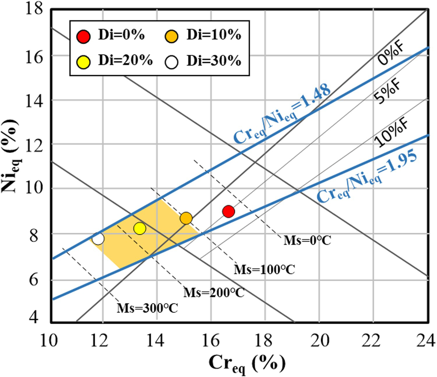
Experimental procedures
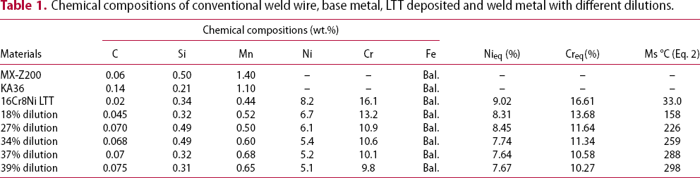
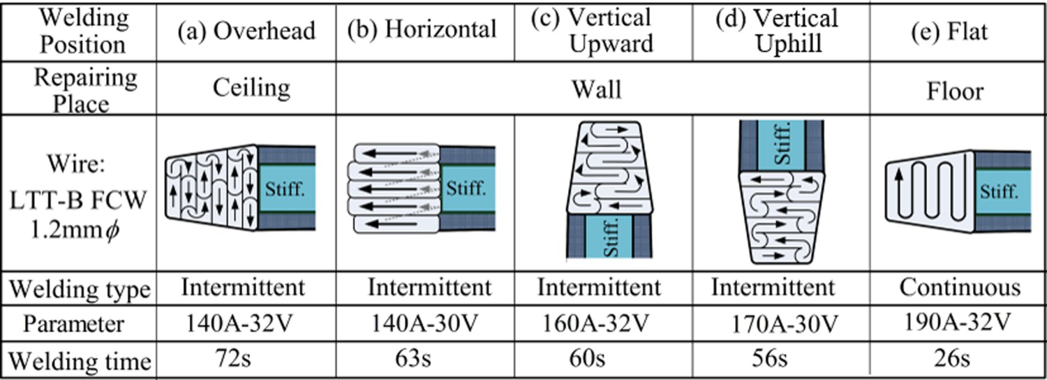
The weldability of the new LTT welding wire was evaluated in different welding positions, including the flat, horizontal, overhead, vertical-upward and uphill positions. Figure 2 shows the schematic of welding procedures to fabricate the repair and stiffening corner boxing fillet joints. The plates were the KA36 steel for ship structures. The fillet and corner boxing welds were fabricated by the conventional flux-cored welding wire MX-Z200. Table S1 lists the welding parameters for fillet and corner boxing fillet welds. Finally, LTT elongated beads of 40–70 mm in length overlaid the boxing weld. With respect to the practical repair welding procedures, the air carbon arc gouging was used to remove the fatigue pre-crack and the old corner boxing weld, followed by repair welding using conventional welding wire and subsequently the overlay-welding LTT elongated bead. As shown in Figure 3, the welding parameters vary depending on the welding positions. It should be noticed that the intermittent welding process by repeating arc on and off was used for LTT elongated bead welding at overhead, horizontal, vertical-upward and vertical-uphill positions to avoid the molten metal drop.
Schematic of welding procedures: (a) stiffening procedure; (b) repair/stiffening procedure. Fabrication procedure of corner boxing joint and elongated beads by different welding positions.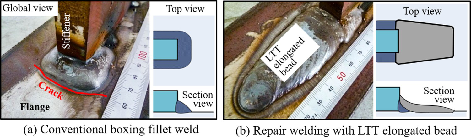
To produce LTT weld metals with different dilutions, three types of welded joints, butt joint, fillet joint and bead-on-plate joint shown in Figures S1–S4, were prepared by CO2 arc welding. Their dilutions were exactly identified by wet chemistry method based on measured Ni content listed in Table 1. Finally, the weld metal dilution of 0%, 17%, 27%, 34%, 37% and 39% were obtained. Since the Ni content in the base metal (KA36) and the conventional weld wire MX-Z200 is rare, it can be assumed that the dilution of LTT weld metal from MX-Z200 is the same as that from KA36. By the way, for the convenience in fabricating weld metals with the dilution of 0% and 37%, on hand base metal SM490A having similar chemical compositions (0.2%C, 0.5%Si, 1.5%Mn) with KA36 and MX-Z200, was employed. Therefore, the use of base metal SM490A did not influence the characteristics of LTT weld metals.
To detect the Ms temperature, solid cylindrical samples extracted from LTT welds with a dimension of ϕ3.0 × 10 mm were heated from room temperature up to 1000°C at a heating rate of 20°C/s, held for 2 s, followed by continuous cooling to room temperature at a cooling rate of 20°C/s using Formaster (Full Automatic Transformation Measuring Equipment). Metallographic study was performed via scanning electron microscopy (SEM). To prevent the formation of stress-induced martensite under the mechanical polishing, samples for SEM were carefully prepared with following procedures. Firstly, we made electropolishing in a solution containing of 95 vol.% ethanol and 5 vol.% perchloric acid (voltage of 30 V for 15 s), then conducted the fine polishing and followed finally etching with a solution of 5 g FeCl3, 15 mL hydrochloric acid and 60 mL distilled water.
To elucidate the microstructural evolution of LTT weld metals during welding process, four specimens with the dilution of 0%, 27%, 34% and 39% were selected for in-situ observation of phase transformation using synchrotron radiation. Rectangular specimens with size of 10 × 10 × 3 mm3 were prepared using wire-cut electric discharge machine. Figure S5 shows the experimental setup where the water-cooled copper anode was mounted on the sample stage. The gas tungsten arc-welding torch was fixed above the upper surface of specimens. The welding current was set to 50 A, lasting for 10 s.
Figure S6 shows the experimental setup and specimen size for miniature uniaxial tensile test. The specimens were extracted in the centre of LTT weld with the length parallel to the welding direction. The micro-tensile testing was conducted with a crosshead speed of 2 μm s−1. Additionally, the hardness of LTT weld metals was measured using a Vickers hardness tester with a load of 2 kg and a dwell time of 15 s.
Results and discussions
Weldability evaluation in different welding positions
It has been clarified that the elongated bead made using 10Cr10Ni solid wire can produce great compressive residual stress in the entire region of elongated bead, and resultantly extends the fatigue life of corner boxing fillet joints at least four times. Unfortunately, this 10Cr10Ni solid wire is limited to flat welding with shielding gas of 80%Ar and 20%CO2 and weaving procedure with a large current of 300 A. In practice, the real working conditions are much more complex regarding repair welding of ship hull structure. There are, besides the floor, other places like ceiling and wall where such a large current continuous welding cannot be used because the molten metal will hang down due to gravity. To prevent the sagging and to obtain an enough penetration as well as good bead shape, it is necessary to develop an intermittent welding method which can make the formation of elongated bead possible by alternately repeating the arc generation period (melting period) and arc extinguishing period (solidification period). In this study, an intermittent welding procedure capable of forming a well-elongated bead shape with a small current of less than 200 A was developed. In addition to the flat position, actual repair operation for ship hull structure needs welding of overhead, horizontal, vertical and flat positions. However, it is uneasy to fabricate LTT elongated beads in these welding positions. Hence, the intermittent welding procedure was employed instead of the continuous weaving welding used in the flat welding. Figure S7 shows the welding conditions and the final elongated beads in different welding positions. It can be seen that a well-elongated bead shape can be obtained and no defects such as weld cracks occurred, demonstrating the applicability of the intermittent welding procedure and the better weldability of the flux-cored LTT welding wire.
Ms temperature of the LTT weld metals
Figure S8(a–c) shows the dilatometric curves of three LTT weld metals with different dilutions. The Ms temperature of the deposited metal (0% dilution), weld metals with dilution of 27% and 37% were, 33°C, 220°C, and 290°C, respectively. Obviously, the Ms temperature of LTT metals increased with increasing the dilution. Here, the volume expansion strain due to the martensitic transformation from Ms temperature to room temperature (R.T.) was defined as the effective volume expansion strain (ϵ), as depicted in Figure 4(a). Using the data from literature [7,8,17,21] and newly measured data (red circle ●), the relationship between Ms temperature and effective volume expansion strain is plotted in Figure 4(b). It can be observed that the LTT weld metals with different dilutions except 0% dilution had a higher effective volume expansion strain ϵ more than 0.4%, which is expected to be conducive to the generation of compressive residual stress [17,21].
Transformation expansion and Ms temperature of LTT weld metals: (a) Definition; (b) effect of Ms temperature on transformation induced volume expansion.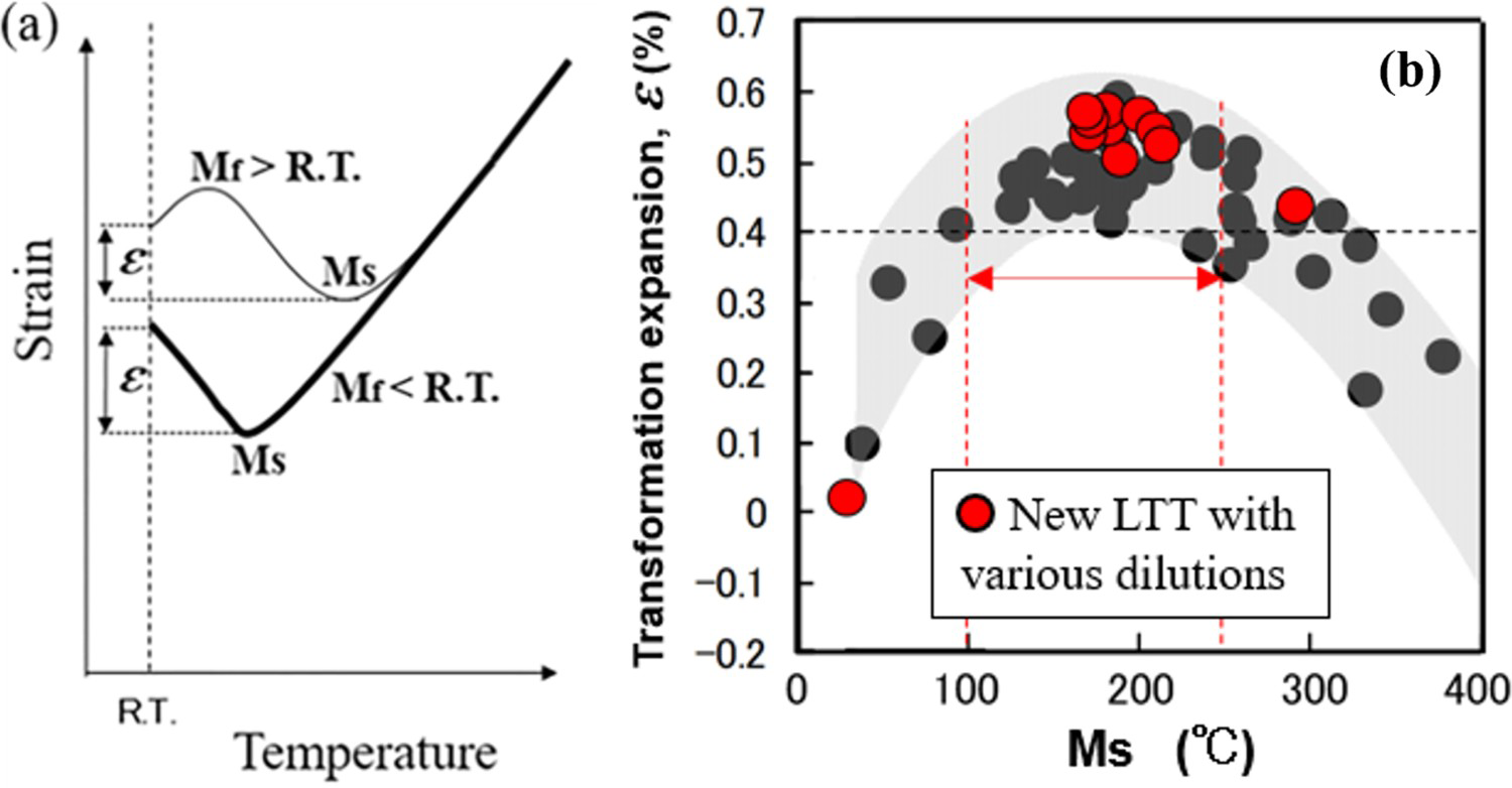
Figure S9 shows the microstructural morphology in the as-welded condition. The deposited metal (0% dilution) mainly contained the retained austenite (γ) and delta ferrite (δ) due to the low martensite start temperature. With increasing the dilution, the delta ferrite and retained austenite gradually decreased, while the martensite increased. The primary microstructures include the delta ferrite and martensite (M). Figure S10 shows the energy dispersive spectrum of the LTT weld metals with the dilution of 0% and 27%. Evidently, the amount of ferrite stabilising element Cr was richer in the delta ferrite, while the austenite and martensite contained a higher percentage of the austenite stabilising element Ni.
In-situ observation and analysis of phase transformation using synchrotron radiation
Figure 5 shows the solidification phase transformation of re-molten LTT weld metals with samples of different dilutions. The diffraction peaks of initial solidification region were either ferritic or austenitic. No other diffraction peaks were found. These observed phases indicated that the initial solidification of LTT weld metals occurred as delta ferrite and austenite during cooling process. From these experimental results, it was confirmed that the solidification mode was FA mode in all samples and LTT weld metals had strong resistance to solidification cracking. This can be the key factor to successfully obtain the LTT elongated welded bead without any cracks in all samples.
In-situ XRD diffraction pattern of initial phase transformation during solidification for the samples of various dilutions.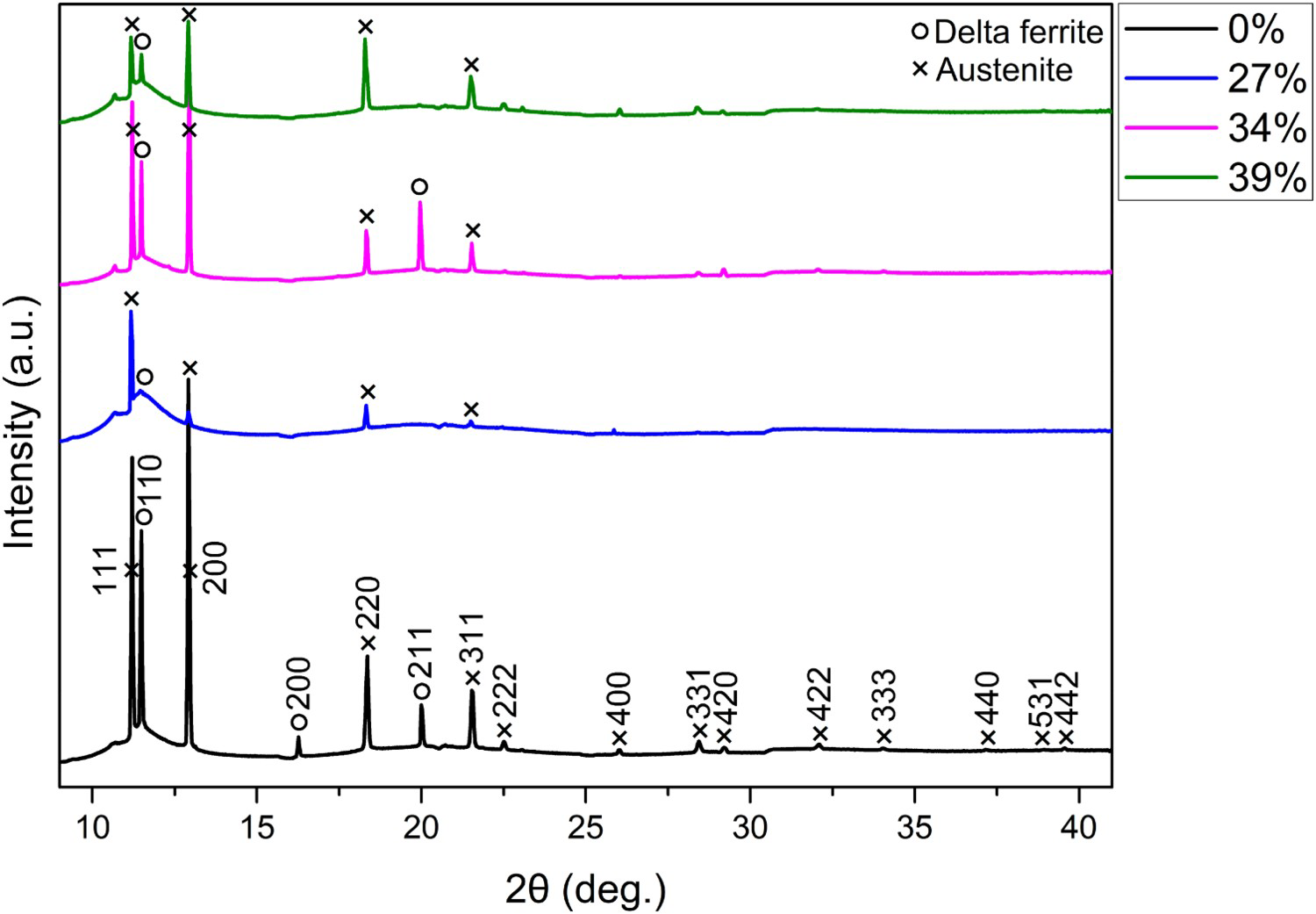
As detailed observed results, Figure S11 shows the in-situ XRD pattern of LTT weld metal with the 0% dilution during heating, melting and cooling stage. Although it is difficult to distinguish the ferritic diffraction peak from the martensitic diffraction peak, the SEM microscopy shows that the microstructure before heating was a mixture of martensite, delta ferrite and retained austenite. Before starting the heating cycle, diffraction patterns of the sample material were recorded at room temperature. The diffraction peaks correspond to martensitic/ferritic and austenitic structures. No other diffraction peaks were found.
In the heating process, the diffraction peaks of martensite and delta ferrite with the body-centred cubic or tetragonal crystal structure decreased and the austenite became predominant when the temperature reached the Ac1 temperature, and then the austenite turned into the liquid metal with temperature rising continuously. During the cooling process, the initial solidification of LTT weld metals occurred as delta ferrite and austenite. So the solidification mode was FA mode even in the sample with the lowest dilution of new LTT welding wire.
Considering the diffraction patterns during cooling, it was remarkable that the retransformation into martensite started at the specific temperature (Ms temperature). And the phase transformation ended up with some retained austenite when cooling down to room temperature, which was clearly visible from the pronounced austenite diffraction peaks shown in Figure S11. There is hardly any transformation of austenite to martensite in weld metal of 0% dilution. This is also in agreement with Ms temperature of 33°C which is close to room temperature. Figure S12 shows the diffraction peaks from the sample of dilution of 34%, which indicates high volume fraction of martensite and small volume fractions of delta ferrite and austenite at room temperature after cooling. Figure S13 schematically shows the microstructure changes of LTT weld metals during the welding thermal cycle. Figures S14 and S15 demonstrate the observed microstructures and the measured retained austenite content in LTT weld metals with different dilutions, respectively.
Tensile properties and hardness of LTT weld metals
To investigate the mechanical properties of LTT weld metals, the uniaxial tensile test for miniature specimen whose size is 1.0, 0.4 and 0.2 mm in the length, width and thickness directions, respectively, was conducted. Figure 6 shows the stress–strain curves of LTT weld metals with the dilution of 27%, 34% and 39%, respectively. The 0.2% offset yield strength of these three LTT weld metals were 812, 955 and 1070 MPa, respectively; and the tensile strength were 973, 1202 and 1242 MPa, respectively. Meanwhile, these three weld metals had the elongations of 16%, 15% and 14.6%, respectively. With increasing the dilution, the yield strength and tensile strength increased while variation in about 1% elongation was negligible. This was mainly due to the reduction of the amount of retained austenite and delta ferrite as the dilution increases. On the whole, the LTT weld metals had satisfied tensile properties.
Engineering stress–strain curves of different LTT weld metals.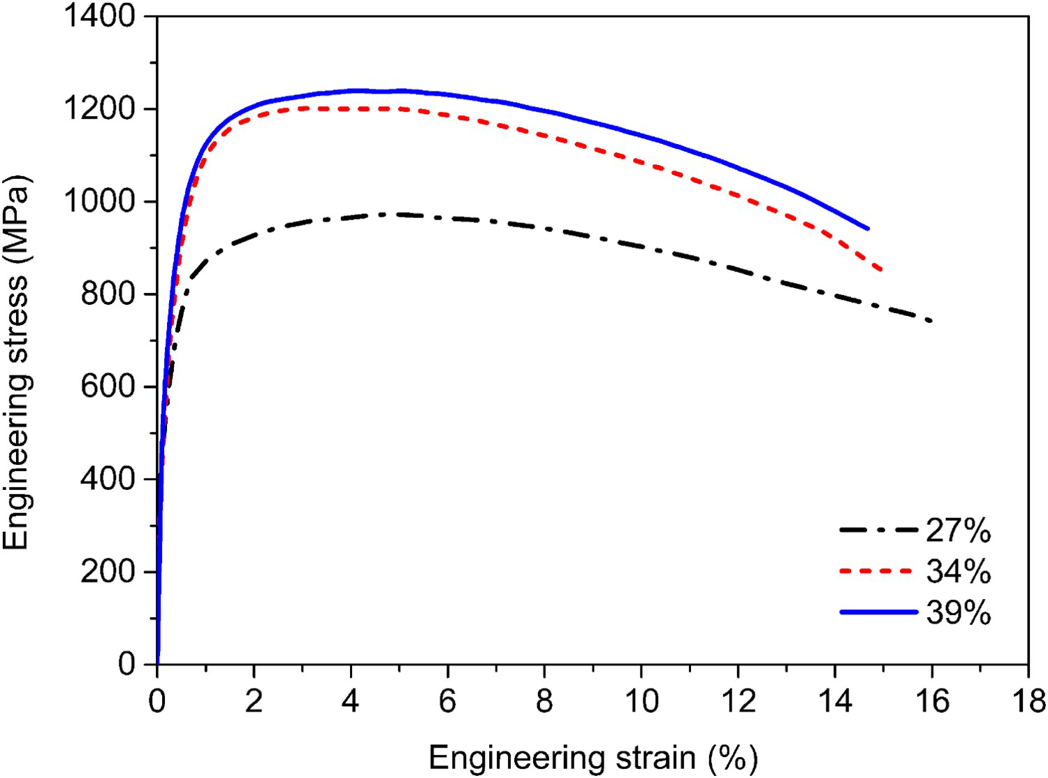
Results of hardness measurements made on all the five elongated LTT weld beads are shown in Figure S16, which can be classified into two groups. The hardness due to the flat and horizontal welding positions has the similar magnitude and their average value is 385 Hv. The hardness due to overhead, vertical-upward and vertical-uphill welding metals are almost the same and their averaged magnitude is about 425 Hv.
Residual stress analysed by FEM and measured by XRD
The confirm the compressive residual stress generation in the LTT elongated beads due to all welding positions, the thermal elastic-plastic analyses were conducted using FEM. The material properties in the analysis for five position welded LTT elongated beads were classified into two groups, flat and horizontal welding group and overhead, vertical-upward and vertical-uphill welding group, according to the measured hardness shown in Figure S16. To determine the detailed material properties in the two groups of the LTT elongated bead, the Ni content in both the flat and vertically welded LTT elongated beads was measured. Ni contents in these two LTT weld beads are 6.1% and 5.2%, respectively. Correspondingly, the LTT-B elongated beads welded in the flat and horizontal positions have the same dilution of 27%, while those welded in other positions share the dilution of 37%.
Based on the welding thermal elastic-plastic theory and author developed in house FEM software JWRIAN [10,11,17,18], the welding residual stress was analysed and the obtained residual stress distribution along the surface of the LTT elongated beads due to all welding positions is shown in Figure 7. In this figure, the abbreviated words ‘AFR-F’, ‘AFR-H’, ‘AFR-V/U’, ‘AFR-V/D’ mean the LTT elongated beads welded by the flat position, the horizontal position, the vertical-upward position and the vertical-uphill position, respectively. The word ‘ER-F’ means the flat welding position using previously developed 10Cr10Ni LTT solid welding wire. The words ‘Boxing joint by conv. wire’ and ‘elongate by conv. wire’ mean the conventional welded joint without elongated bead and that with elongated bead using conventional wire. The word ‘Measurement data by XRD’ means the XRD measurement in the flat welded elongated bead. From both analysed and measured results, it can be known that the large compressive residual stress was certainly generated in the elongated beads regardless the welding positions, compared with the tensile residual stress at the cases of ‘Boxing joint by conv. wire’ and ‘elongate by conv. Wire’. This compressive residual stress induced in the LTT elongated beads by all position repair welding can be extremely helpful for fatigue life extension of welded structures.
Compressive residual stress distributions along LTT elongated beads welded by all positions.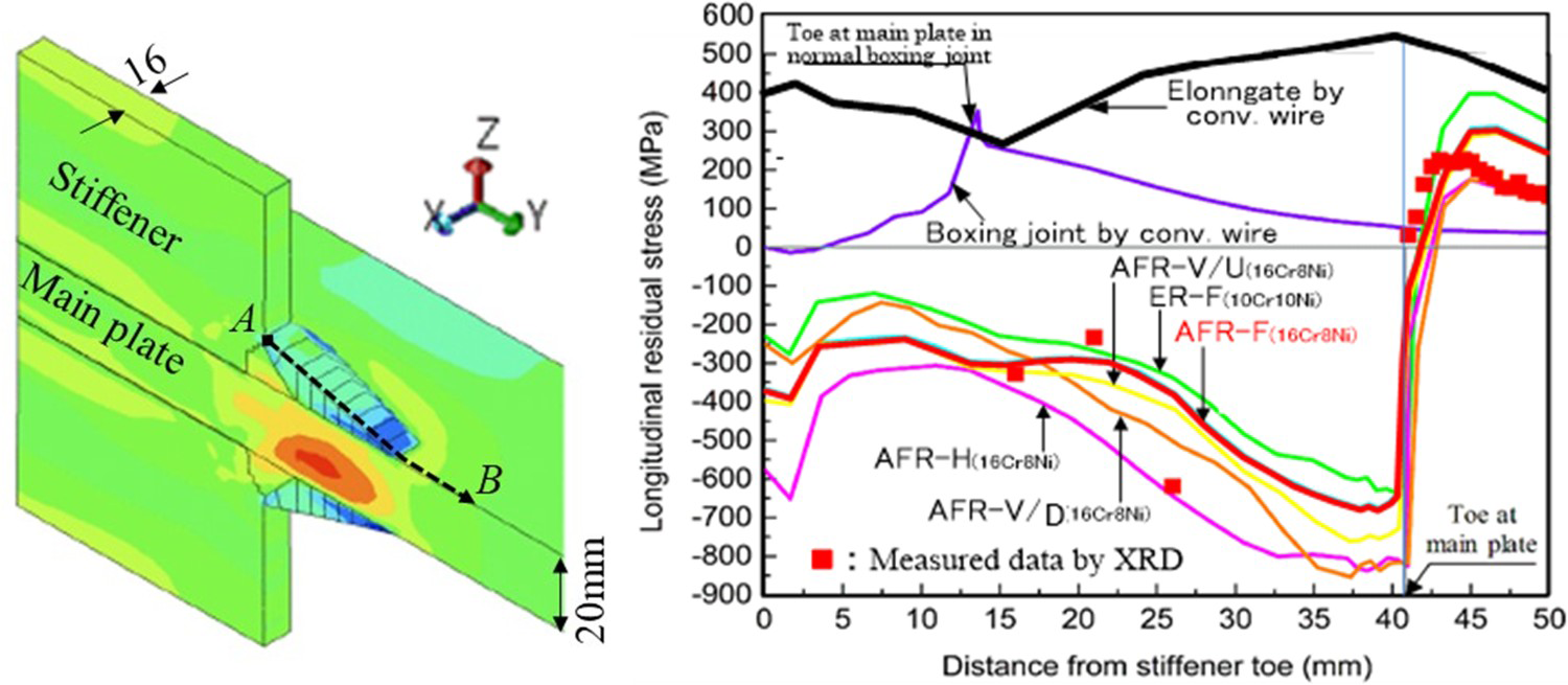
As mentioned before, the dilution and martensite start (Ms) temperature vary in the range of 18%–39% in different welding positions. To our knowledge, the Ms temperature of the 10Cr-10Ni deposited metal is 180°C. With the dilution changing in the same range, the Ms temperatures of 10Cr-10Ni weld metals change from 290°C to 409°C according to Equations (1) and (2). And then the martensitic transformation exhausts above ambient temperature, resulting in a build-up tensile stress due to thermal contraction during the following cooling process. Therefore, the effect of dilution must be considered when using LTT welding wire.
Conclusions
To extend fatigue life of corner boxing welded joint in repair welding, the optimal chemical compositions of a new LTT welding material with consideration of dilutions in elongated bead were designed and its flux-cored welding wire was developed for all welding positions. Accordingly, detailed studies were conducted to investigate the weldability, microstructures, transformation behaviours, mechanical properties and residual stress of the LTT welds. Based on the above studies, following conclusions have been drawn:
The positional welding (horizontal, vertical and overhead) with intermittent welding, was demonstrated using newly developed LTT flux cored wire with 100% CO2 as shielding gas. The LTT weld metals with the dilution range from 27% to 37% can generate a volume expansion strain of martensitic transformation higher than 0.4%. The LTT weld metals with different dilutions have high strength and good elongation due to the existence of both the martensite and austenite phases. The solidification mode of the LTT weld metals is observed to be the ferritic-austenitic mode, which is of great importance to reduce the solidification cracking sensitivity. The compressive residual stress in LTT elongated beads welded by all positions is confirmed by numerical analysis and XRD measurement.
Footnotes
Acknowledgements
The synchrotron radiation experiments were performed using the BL46XU of SPring-8 supported by Dr M. Sato under the approval of JASRI (Proposal No. 2021A1613). Authors sincerely express thanks to team members of this national project JST A-STEP (VP30318088710), Profs. H. Murakawa, N. Osawa, H. Yajima, C. Shiga, K. Okada and Mr T. Matsusaki, Mr K. Matsumoto, Mr Y. Murata. Authors also appreciate Prof. T. Nakamura and Ms Y. Baba for measuring weld metal properties.
Disclosure statement
No potential conflict of interest was reported by the author(s).