
Abstract
The weldability of high-strength steels (HSSs) is limited by their loss of strength, toughness and fatigue properties. In demanding applications, the fatigue properties of welds are among the strictest requirements. This paper presents a weldability analysis focusing on the microstructure and fatigue properties of 6 mm thick S690 and S355 HSS plates joined by friction stir welding. Their fatigue properties are compared to design recommendations and to fatigue properties obtained with other welding techniques. Results show that the high-quality friction stir welded steel joints outperform high-quality arc welds and FAT80 design recommendations. The fatigue strength of the friction stir welded joints is increased with material yield strength. The mechanisms governing crack initiation at different maximum stress levels are discussed.
Introduction
Weldability is nowadays a major limitation to the widespread use of modern high-strength steels (HSS). These combine high strength with relatively good toughness and could be used in a wide range of industrial applications to achieve weight reduction without compromising load-bearing capacity. Yet, due to the limited knowledge on their fatigue resistance, current design rules prevent taking full advantage of the benefits these HSS can provide to welded structural applications [1, 2].
Previous work has shown the importance of weld quality for yield-limit-dependent increase in fatigue strength [3]. One advanced welding technology that promises high weld quality is friction stir welding (FSW) [4]. The benefits to fatigue behaviour of FSW over fusion welding have been demonstrated for aluminium alloys [5], particularly in aeronautic applications, in as-welded conditions [6] and with surface improvements techniques [7]. This has increased the interest in extending the advantages of FSW to steels. HSS produced by thermomechanical controlled processing (TMCP) could benefit from FSW since it can join steels in similar temperature domains [8] as in the last stages of the steel making process [9].
Thomas et al. [10] demonstrated the feasibility of FSW of steels in 1999 on a 12% chromium alloy and a low carbon steel. Since then, several authors addressed this subject, including studies in numerical modelling [11, 12] and economic analysis [13]. FSW was considered superior to conventional fusion welding in many categories, although tooling costs and limited service life are viewed as obstacles to a faster uptake by industry.
Studies reported that the stirred zone (SZ) of ferrous metals displays a dynamically recovered microstructure [14]. This suggests that FSW of ferrous metals develops in a similar way to that of aluminium. The trend is analogous: compared to fusion welding, peak temperatures are lower and the heat-affected zone (HAZ) is smaller. The grain size in the processed zone is smaller and, absent critical defects, the strength increases [15, 16]. In addition, complex phase transformations can occur [17] and mechanical properties can be improved compared to some base materials (BMs) [18, 19].
Studies show that FSW produces less distortion and better fatigue performance than submerged arc welding (SAW) [20]. A36-GL [21] and DH36 [22] steels welded by FSW reached fatigue strength values significantly above design recommendations [1, 2]. A similar effect was observed for high-quality fusion welds [23, 24]. Earlier results [3] also showed that fatigue behaviour benefits from higher BM strength. However, in the case of fusion welds this effect is limited by weld quality.
The present work investigates the potential benefits of combining FSW with the superior properties of two industrially relevant grades in steel plates, S355 and S690. The study is mostly focused on the S690, but S355 is also included to better understand the correlation between yield and fatigue strength in FSW joints.
Experimental procedure
Materials and FSW conditions
Chemical composition of S690 [wt-%].
Chemical composition of S355 [wt-%].
Single-pass welds were made along the rolling direction (RD), in square butt joint between two plates with milled edges. The plates were firmly clamped and were joined using tools made from pcBN-based W-Re composite materials with 70 vol.-% pcBN [25]. The S690 was welded with a travel speed of 60 mm min−1 and a rotation speed of 300 rev min−1 and the S355 was welded with the travel speed of 350 mm min−1 and the rotation speed of 450 rev min−1. In both cases, FSW was performed in position control with a constant plunging depth of 6.0 mm and the tool and processed surface were gas shielded with a 20 L min−1 flow of argon. The welded samples were visually inspected and showed smooth top surfaces with continuously spaced striates without flash formation and no evidence of root defects.
Sample extraction plan
The transient weld regions were excluded by discarding 50 mm from both the star and the end of the welds. This length of 50 mm is based on ISO 25239-3. Although this standard was drafted for FSW of aluminium, considering the lower thermal diffusivity of steels it is reasonable to assume that the transient zone extension in steel FSW should be equal, or smaller, than that in aluminium FSW. Test specimens for optical microscopy (OM), fatigue and microhardness testing were extracted from the remaining, stable region, of each weld. Specimens for fatigue testing were produced according to ISO 1099.
Metallographic examination and microhardness measurements
Samples for OM were grinded, polished, and etched with nital. The macrographs in Figure 1 identify the different weld zones: BM; SZ; and HAZ. The advancing side (AS) and retreating side (RS) are identified when relevant.
Macrographs of the friction stir welded S690 (left) S355 (right) cross-sections.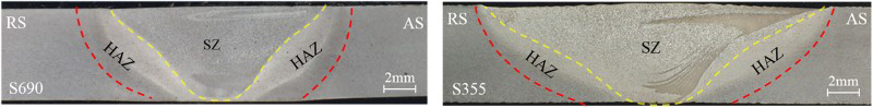
Microhardness was measured on cross-sections extracted from the middle of the welds, a region that is representative of the stable length of each weld. The measurements performed on an instrumented tester with a load of 9.8 N are equivalent to HV1. The measurements matrix covers a 37 × 4 mm area, with 0.5 mm spacing between measurements, providing a hardness map covering all the weld zones.
Fatigue testing
The specimens for fatigue testing were cut from the welded plates by waterjet and their edges were polished before testing to avoid edge cracking. All specimens were tested in the as-welded condition. The grip ends of the specimens were grinded to avoid secondary bending due to misalignments while the specimen was clamped in the fatigue test machine. Secondary bending stress was monitored via strain gauges. All tests were carried out with a constant amplitude loading, load ratio R = 0.1, and frequency of 20 Hz. The number of cycles to failure was recorded at fracture. A run-out limit of 2 million load cycles was applied.
Analysis of the results
Microstructure and hardness
The macrographs of the polished and etched cross-sections (Figure 1) show neither evidence of internal defects nor lack of penetration (LOP) defects. The SZ of the FSW of S355 (hereafter S355-FSW) is wider than that of the FSW of S690 (hereafter S690-FSW). The macrographs reveal the different weld zones emphasising the distinct thermal and thermomechanical history of the HAZ and TMAZ including the SZ. Figure 2 shows the microstructure of the S690 and S355 BMs and of their SZ together with the respective EBSD maps.
Microstructure and EBSD IPF of: (a) the S690 BM; (b) the S690-FSW SZ; (c) the S355 BM; (d) the S355-FSW SZ (notice the different scale in the EBSD map).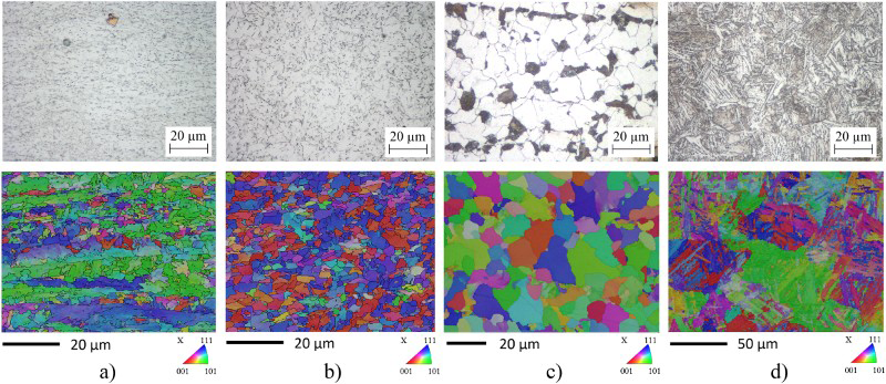
The S690 BM (rolled + direct quenched), in Figure 2(a), exhibits a fine elongated ferrite-bainite microstructure with evidence of the RD and small, homogeneously distributed, precipitates. Figure 2(b) shows the S690-FSW SZ with microstructural features similar to those of the BM, an isotropic grain structure of somewhat larger size, larger ferrite domain and lower density of precipitates. The preferred orientation in the BM is [101] (Figure 2(a)) while in the SZ (Figure 2(b)) the refined grains are more randomly oriented.
In the S355-FSW, the microstructural changes are more significant. The S355 BM, in Figure 2(c), exhibits a microstructure with coarse polygonal ferrite and some Pearlite islands. The S355-FSW SZ (Figure 2(d)) contains lath bainite and acicular ferrite and larger grains than the original BM.
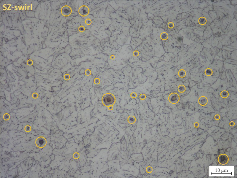
Figure 3 shows the hardness maps of the weld cross-sections superimposed on the weld macrographs. The hardness of the S690-FSW SZ undermatches that of the BM, due to its larger grain size and lower density of precipitates. A more detailed analysis of this map reveals four zones with distinct hardness values: (i) the BM (300 HV1); (ii) the ‘hard’ region of the HAZ (about 330 HV1); (iii) the ‘soft’ region of the HAZ (about 220 HV1); and (iv) the SZ (275 HV1). Compared to the BM, the hardness increases slightly in the ‘hard’ HAZ then decreases, sharply, in the ‘soft’ HAZ. The average hardness in the SZ is higher than in the ‘soft’ HAZ but lower than in the BM, except for a region (marked ‘x’ in Figure 3) with about 350 HV1 where the accumulation of hard precipitates occurred (see Figure 4). These were identified as titanium nitride precipitates by energy dispersive spectroscopy. Overall, the hardness variation in the S690-FSW is similar to that observed in arc welds [26] and the peak values are acceptable.
Hardness distribution maps of the FSW cross-sections. Micrograph of the hard sub-zone in the SZ of the S690-FSW steel emphasising the accumulation of hard phase precipitates (circled).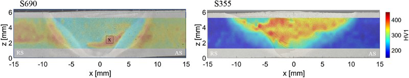
The hardness distribution in the S355-FSW is comparable to measurements by Toumpis et al. [22] on the same material and with similar FSW parameters. Contrasting with the S690-FSW there is a hardness overmatch in the HAZ compared to the BM. The hardness increases gradually from the BM (about 180 HV1) into the SZ (350 HV1) with peak values about double those of the BM. For both steels the hardness near the toe is slightly lower at the RS than at the AS.
Fatigue strength
Summary of fatigue test results for friction stir welded joint.
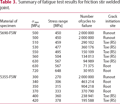
Figure 5 shows the S–N curves for FSW compared to the fatigue strength of S690 BM as well as to high-quality SAW of S355 and MAG welds of S690 with different levels of heat input obtained from Refs. [24, 26], respectively. It includes data points, the fitted S–N curves at 50 and 97.7% probability of survival, and the FAT class of 80 MPa according to IIW design recommendations [2].
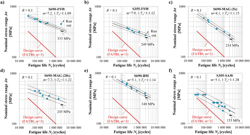
Figures 5(a,b) show S–N curves for the S690-FSW and S355-FSW, respectively. The characteristic fatigue strength of S690-FSW (335 MPa at 2 million load cycles) is significantly higher than FAT80. It is almost the same as the BM, 340 MPa (Figure 5(e)), and is higher than that of high-quality arc welded joints (Figure 5(c,d)). A similar trend is observed for the S355-FSW. Its characteristic fatigue strength, 249 MPa, is higher than that of a high quality (smoothed) arc welded joint, 153 MPa (see Figure 5(f)). These results clearly show a fatigue strength increase with material yield strength. This increase appears to be similar in high-quality arc welded joints, as shown in Figure 5 and reported in Refs. [3, 16].
The characteristic fatigue strength at 2 million load cycles as a function of material yield strength.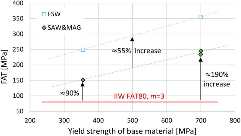
Figure 6 compares the fatigue strength of the welded specimens to FAT80. The fatigue strength of high quality arc welded S355 and S690 joints is about 90 and 190% higher than FAT80, respectively. For the S355-FSW and S690-FSW this increase was an additional 55% higher than the high-quality arc welded joints, i.e. about 311 and 425% higher than FAT80, respectively.
Fracture surface analysis
The data in Table 3 emphasise another important detail concerning the fracture initiation. There is a distinct fatigue behaviour difference between the S355-FSW and the S690-FSW. For the S690-FSW, the fracture at high maximum stresses initiates at the root. On the other hand, for lower maximum stresses fracture initiates from the toe, at the RS. The S355-FSW exhibits an opposite behaviour: at high maximum stress levels, fractures initiate at the toe on the RS and only for lower maximum stresses do the fractures initiate from the root. This is an important observation, not previously reported, demands further investigation to better understand the influence of the microstructure on the crack initiation mechanisms.
Fracture behaviour of the S690-FSW and S355-FSW specimens.
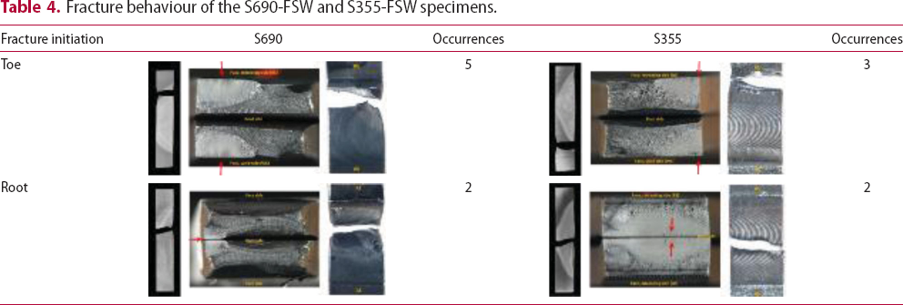
From the seven S690-FSW specimens, five fractures initiated at the face, on the RS, while the remaining two fractures initiated at the root side. The two root side fractures did not start at the original abutting surfaces (i.e. fracture initiation was not caused by LOP). In all the fractures (face and root side) the crack initiation site coincided with the transient zone between the HAZ and the SZ, where the hardness gradient is steepest. One of the S690-FSW samples that fractured from the face side exhibited a secondary, incomplete, crack on the root side (Figure 7). This sample was tested with σMAX = 630 MPa and fractured at the toe (on the RS). This level of maximum stress was the transition between the fracture initiation at the root (for higher stress values) and fracture initiation at the toe (for lower stress values).
Fractured specimen of fatigue test S690-FSW with σMAX = 630 MPa and fracture at the toe (RS), depicting a secondary crack initiation site on the root side (circled).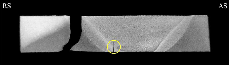
Of these two, concurrent, initiation and propagation sites it was the face side crack that failed first. Both cracks propagated vertically from their respective initiation sites but while the face side crack propagated into the HAZ the root side crack propagated into the SZ. When the specimen finally failed the length of the root side crack had only reached 1/3 the thickness of the specimen. This suggests better toughness properties in the SZ of FSW of HSS, which should be confirmed by further investigation.
From the five S355-FSW specimens, two fractures initiated at the face, on the RS, while the remaining fractures initiated at the root side. The three root side fractures started at low maximum stress levels and high number of cycles at the original position of the abutting surfaces. This suggests that, since there was no LOP, the fracture initiation was related to the local alignment of oxide particles. Again, both face side fractures started at the transient zone between the HAZ and the SZ (also corresponding to the edge of the tool shoulder).
Crack initiation at the interface between the SZ and the HAZ, where the hardness gradient is steepest, appears to be a recurring pattern. This indicates that, absent any defects (e.g. LOP), this location is a preferential site for crack initiation regardless of the roughness/geometry, and should, therefore, be investigated further.
Conclusions
The fatigue properties of two modern HSSs welded by FSW were investigated. The most important conclusions are the following:
S690 and S355 friction stir welded joints showed significantly higher fatigue strength than FAT80 and high-quality arc welded joints of the same steels. Their fatigue strength was about 55% higher than high-quality arc welded joints. The fatigue strength of S355-FSW and S690-FSW was about 311 and 425% of FAT80, respectively. The fatigue strength of S690-FSW was about 40% higher than that of S355-FSW. The fatigue strength increased with the yield strength. Microstructural analysis showed that the S690-FSW SZ exhibits microstructural features similar those of the BM but with somewhat larger ferrite domain and lower density of precipitates, resulting in hardness undermatching compared to the BM. The microstructural changes in S355-FSW are more significant, with the SZ containing lath bainite and acicular ferrite in larger grains than in the original microstructure, overmatching the hardness of the original BM. For the S690-FSW all the crack initiation sites, both at the face and at the root, occurred at the interface between the SZ and the HAZ, where the hardness gradient is steepest. The pattern for the localisation of the fracture versus the maximum stress level was different between the S690-FSW and S355-FSW specimens. For the S690-FSW the fracture at high maximum stresses was localised at the SZ, while fractures at the toe only start at lower maximum stresses. The S355-FSW exhibited the opposite behaviour.
Footnotes
Acknowledgements
The work is part of the Breakthrough Steels and Applications (BSA) programmes of the Finnish Metals and Engineering Competence Cluster (FIMECC). All the support is gratefully appreciated.
Disclosure statement
No potential conflict of interest was reported by the authors.