
Abstract
This case report describes a newly developed prosthetic arm for a world class trans-humeral amputee cyclist. The proposed solution consists of a new prosthetic kit that was designed to meet requirements of weight, freedom of movement and precise positioning for the disciplines of time-trial, pursuit, road and team sprint. The kit is made of different attachments that can be changed depending on the event the athlete is competing in. The prosthesis is composed of an extended socket made of composite materials, an arm made of aluminum tubes, a universal joint for the junction with the handlebars and different attachments for each bicycle. The system's weight is kept to a minimum using finite element analysis and careful material selection. The universal joint provides the angular degrees of freedom required to allow the athlete to stand up while pedaling, a freedom of movement lost since amputation. In this case report, the athlete's needs are presented and followed by the design of the product using Finite Element modeling. Results are then presented and discussed. This prosthetic kit was used by the athlete for the 2008 Paralympics games in Beijing.
Introduction
This paper presents a case report of the design of a prosthesis kit made specifically for a paralympic cyclist. The project was conducted by four undergraduate students in the context of a two-year design project. The main objective of the project was to design a prosthesis that matches the performance of two healthy arms, but at a lower weight. Furthermore, the complexity and the price of the prosthesis had to be kept to a minimum. The priority was to give the athlete the freedom to move and the possibility to exert all forces as if he had two healthy arms. Then, the optimization of the weight and structural resistance with composite materials was executed. Finally, a prosthetic kit was produced to give the athlete the optimal positions for the events of: time-trial, pursuit, road and team sprint. The project has been approved for human testing by the research ethics committee of the University of Sherbrooke.
Needs and specifications
Three major needs were targeted in order to help the athlete achieve higher performance. First, the prosthesis had to give the athlete the possibility to stand up while pedaling. Second, the weight had to be minimal while the prosthesis had to resist the forces generated by the athlete. Third, the prosthetic arm had to permit the optimal position for each discipline. Also, respecting the UCI (Union Cycliste Internationale) standards and assuring safety were of paramount importance in the development of the project. These needs were translated into the technical specifications discussed below.
The life cycle of the prosthetic arm was fixed to 86,000 cycles, which represents roughly two years of use. This number only considers the cycles where the cyclist is giving its maximum effort, which typically represents about 1 km in a 40 km race. According to Soden
[1]
and with extrapolation of the athlete's specific needs, the maximal pulling force applied by our cyclist is 841 N and the maximal pushing force is 420 N. As shown in Figure 1, these forces are aligned with the axis of the arm (y axis). The forces in the x and z directions were determined through various trials by measuring the maximum output forces of the athlete with a linear dynamometer. The athlete was asked to be in the position in which he judged he could produce the highest amplitude force. This was repeated several times and the mean amplitude was kept as the maximal force that could be achieved in the direction of interest. Table I summarizes the results for these forces.
Directions of the axis in the time-trial configuration.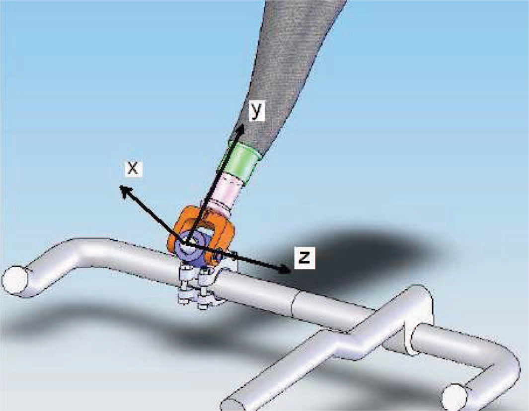
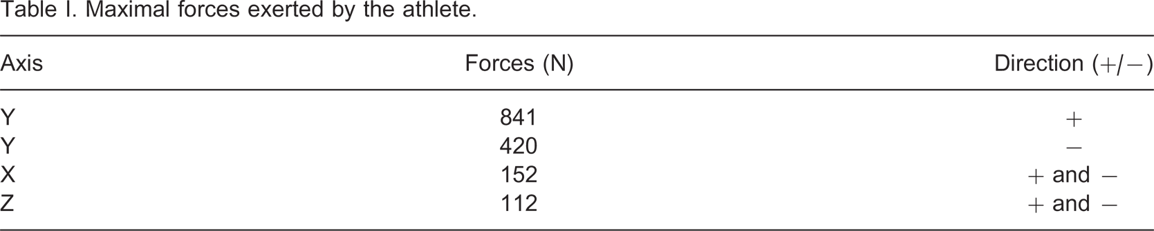
Maximal forces exerted by the athlete.
The need to reproduce the movement of a healthy arm is essential for the performance of the athlete. It must permit the ‘dancing’ motion used by cyclists when climbing a hill or sprinting.
Furthermore, the design must allow an aerodynamic position in each discipline. Using video analysis, the ‘dancing’ motion and various aerodynamic positions were studied. It was determined that shoulder movement should be ± 6.5° with the vertical in the frontal plane.
According to UCI rule 16.15.004, ‘Artificial handgrips and prosthesis are allowed on upper disabled limbs, but not fixed to the cycle’. In accordance with these regulations, the concept must resist the forces applied by the athlete in normal operation while being able to disengage easily. The maximum disengaging force was conservatively set to 25 N.
Development and design
The specifications discussed in the previous section were used to design the prosthesis kit presented in this article. The kit consists of the following five subsystems (see Figure 2): Attachments used to fix the prosthetic arm on the different handlebars; A universal joint which permits the angular degrees of freedom needed by the athlete to stand up on his bike; A set of extensible aluminum tubes to adjust the length of the prosthetic arm; A socket; A harness to affix the socket to the athlete's body (not shown here).
Since distinct handlebars are used to perform each cycling discipline, a different attachment was developed for each discipline. The distinction between the different handlebars is the diameter of the attachment zone and the attachment orientation at the handlebar. Since different hand positions are normally needed during a single race, an in-between position had to be identified to fix all attachments. That position was determined by carrying out video analysis along with consulting the athlete and the coach.
Means to disengage the prosthesis from the bike had to be designed to respect UCI regulation. To respect this regulation, a groove was added in the cylinder of the joint (Figure 2), which can rotate around the pin. A ball plunger was then placed through a hole in the pin of the attachment, which is immobile. The position of the groove was determined using video analysis of the cyclist and is positioned at an angle which cannot be reached by the prosthetic arm during normal cycling activities. When the cyclist is pedaling, the ball plunger is not aligned with the groove. This position increases the force needed to let off the prosthetic arm to about 100 N (force aligned with the pin axis). When the cyclist is at rest, he can turn his body to align the groove with the ball plunger, which makes the prosthesis easier to disengage. In this case, the vertical force required is around 25 N. Figure 2 shows the disengagement mechanism and the attachment.
Disengagement system for the road configuration.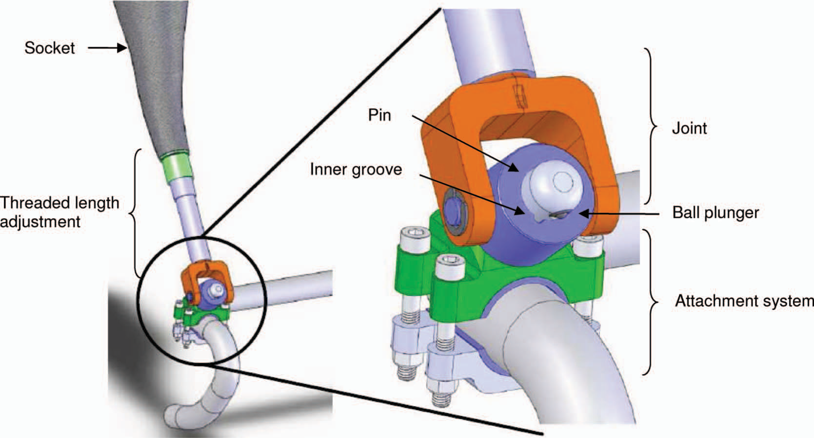
The system offers safety to the athlete because while he is pedaling, the fixation system can sustain all the forces without going off too easily. If a fall was to occur, the forces encountered would be high enough to release the prosthetic arm.
The socket was analyzed with FEM (finite element method), using NX NASTRAN, to determine the final shape. A load case has been defined according to the maximum forces listed in Table I. Only forces leading to compressive loads were considered because of the much lower resistance of composite materials in compression loading. For the FEM model, the proximal end of the socket was embedded and the load condition was applied at the center of the distal end.
Multiple criteria of failure are used for the design of composites structures. One of the most used is the Tsai-Wu failure criteria and the latter was chosen here for its ability to differentiate tension and compression failure.
[2]
A value of 1 indicates that the material has failed to sustain the stresses deployed. Multiple lay-ups have been tested using the model to validate the overall performance. Figure 3 shows the results obtained using the final configuration. It can be seen that the maximal index is 0.04 (red zone) in the proposed design. Since this index is only present at the exact application of the force, it should not be considered as accurate because of the Saint-Venant effect.
[3]
For this reason, the maximal index should be assumed to be around 0.03 (green to yellow zone on Figure 3). Accordingly, a minimal safety factor of 20 is achieved for the composite socket. Also, special considerations were put into the design of the socket joint. In the end, a tapered shape with a rough surface finish
[4]
was used.
In this Figure the gradation of colors shows the Tsai-Wu laminate failure index for the load case discussed earlier.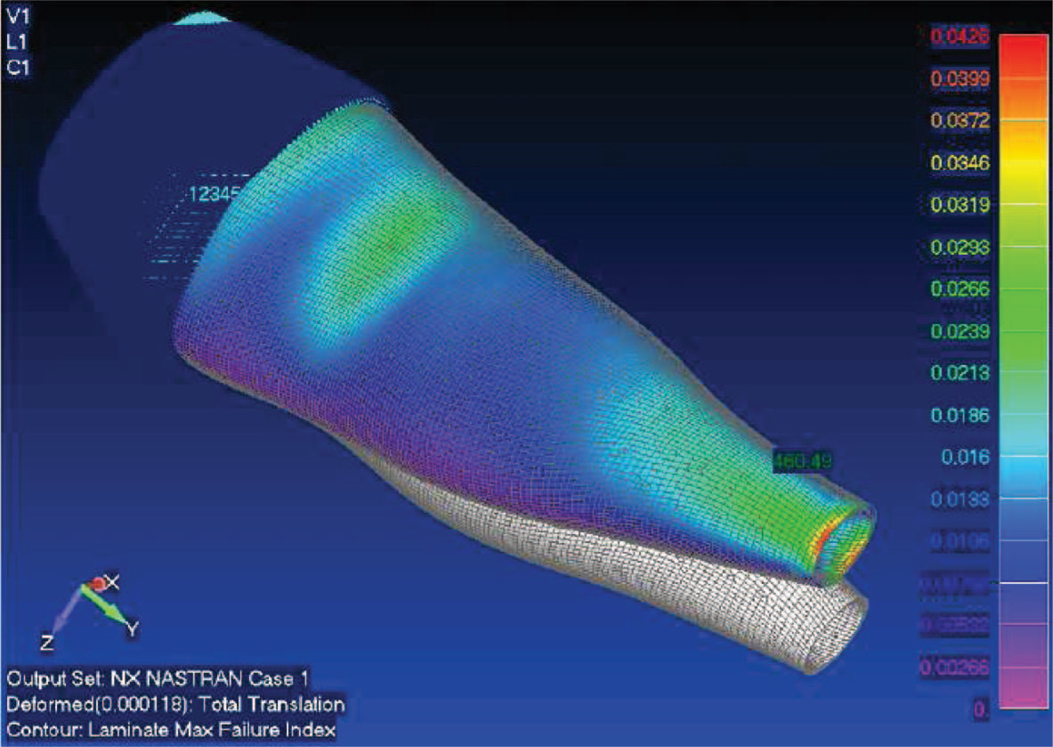
For all critical parts of the prosthetic arm (junctions and socket), destructive tests were performed. It was confirmed that the prosthetic arm is able to support all loads conditions with a minimal safety factor of 1.5 for static loads and 1.1 for fatigue loads. These smallest safety factors were assessed using yield strength and they are respectively found within the upper body of the attachment and the threaded part of the length adjustment (see Figure 2).
Results
Figure 4 shows the four attachments made for the four events mentioned previously. The part bodies are made from 6061-T6 aluminum and the cylindrical pins from 304 stainless steel. Cylindrical half-shell shims were used to adapt to each handlebar diameters.
Different attachments for, from left to right: time-trial, team pursuit, individual pursuit and road.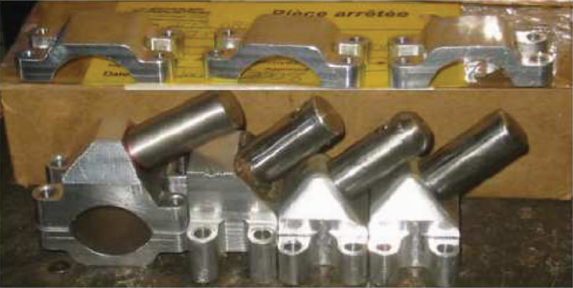
Figure 5 shows the universal joint. The cylinder and the clamp are both made of 304 stainless steel. Disposable Nylatron sleeves have also been added between the cylinder and the clamp to reduce friction and wear.
Universal joint.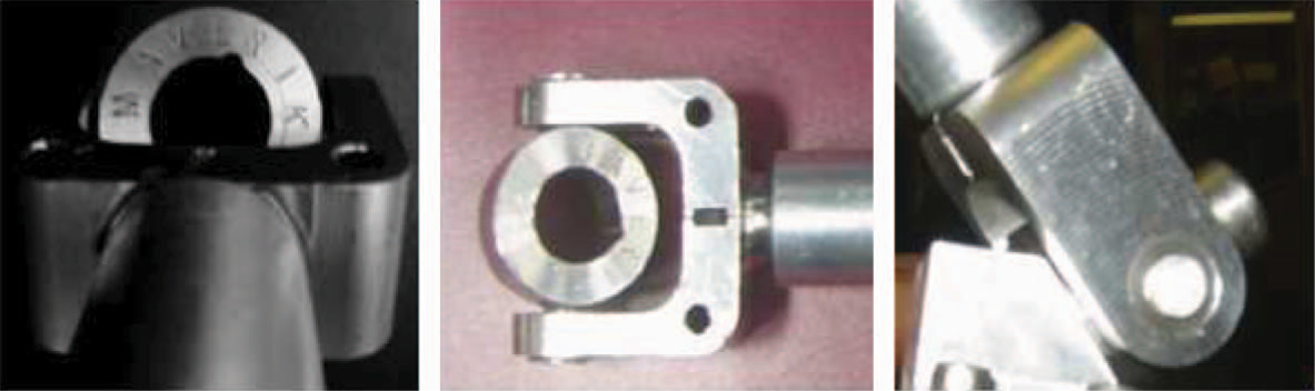
The final socket design is composed of one base layer of nyglass (65% fiberglass and 35% nylon), six layers of fiberglass [0° 90°] and one final layer of nyglass. The used matrix was epoxy resin (Orthocryl 617H55). To reduce the overall weight and to provide a better structural resistance to buckling, a foam core (Pedilen 617H32-300) was added in the extended length at the end of the stump cavity. Also, a hole was added at the bottom of the socket to evacuate the stump sweat. Figure 6 shows the socket.
Socket with his joint (before painting).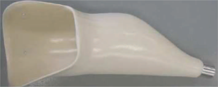
Finally, Figure 7 shows the complete prosthetic arm (without harness and attachments). The final weight of the prosthetic arm is 1065 g (road configuration) without its attachment and 1264 g with it.
Complete prosthetic arm (road configuration).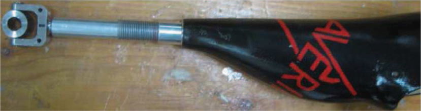
Discussion and conclusion
The prosthetic arm proposed in this article was well received by the athlete. Indeed, it met all the principal needs that he stated. Moreover, the prosthetic arm can be used in all disciplines. The comfort experienced and the ease of use added to the overall athlete's appreciation. It should be noted that this prosthetic was used by the athlete at the 2008 Paralympics games, which demonstrates his great trust in the product. Figure 8 shows the athlete in action during the Paralympics games.
The final prosthetic arm used at the 2008 Paralympics games.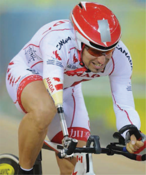
This new design has helped the athlete achieve better performances by answering the three major needs identified at the beginning of the project. The design of the attachment permitted rotation around the y axis and the x axis (Figure 1) which enabled the athlete to stand up while pedaling. The weight of the new prosthesis was lowered by 25% compared to his old prosthesis while conserving a great resistance. Moreover, this product allowed the athlete to optimize his position depending on which event he is competing in.
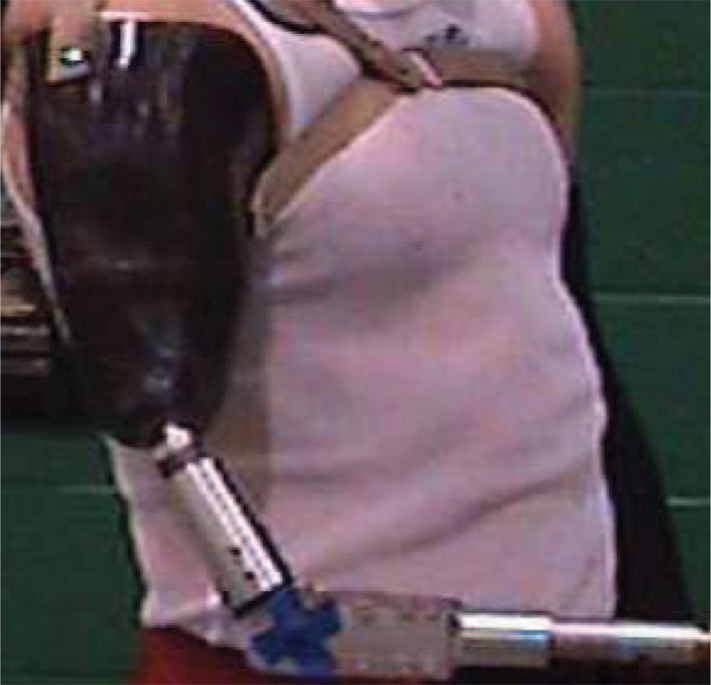
Some problems were identified by the athlete. These are the lack of ability to modify the shoulder/handlebar distance (in real time) and the fact that the fixation point is immobile during a race. The distance aspect has been analyzed and the problem was solved by adding an elbow, which can be operated in real time by electrical control. This new system has shown some good preliminary results, see Figures 9 and 10.
Elbow parts of the prosthetic arm. Prosthetic prototype with the addition of an elbow.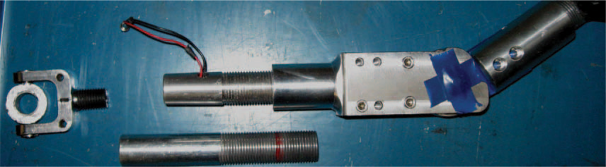
Even with the encountered shortcomings, the athlete feels that the benefits gained with his new prosthetic arm counterbalance these shortcomings. The simplicity and effectiveness of the prosthetic arm system developed in this study can easily be reproduced at low cost for any trans-humeral amputee interested in cycling and thus contribute in improving amputees' quality of life.
Footnotes
Acknowledgements
The authors would like to mention the special contribution of the CRE and Scholer Industriel who participated generously in the project. Also, special thanks are made to Prof. Cécile Smeesters, Prof. Denis Rancourt, René St-Amant and Marc-André Cyr who provided great advices and support throughout the project.