
Abstract
Static wrist orthoses (SWOs) are used in the treatment of carpal tunnel syndrome (CTS) with some drawbacks. As an alternate approach to SWOs, an active closed-loop wrist control strategy based on the principles of functional electrical stimulation was proposed to limit wrist movements. The purpose of the study was to determine whether the proposed ‘neuro-orthosis’ (NeO) system resulted in less restriction in the hand compared to clinically accepted custom-made SWOs while limiting the wrist movements. A case-control study was designed to determine the specific effects of the system on patients with CTS. A total of 24 right-handed female volunteers (12: CTS, 12: healthy) participated in the study. Function, dexterity, and strengths were measured under three different testing conditions: without orthosis, with SWO, and with the NeO system. Maximum angles in one subtest while the NeO system was on and off and general discomfort levels in SWO and NeO test conditions were recorded. The NeO system resulted in less restriction with respect to SWO and provided considerable angular limitation compared to placebo. It was concluded that the proposed prototype control system can be a good candidate to limit the wrist movements in place of SWOs with a better degree of freedom in patients with CTS.
Introduction
Carpal tunnel syndrome (CTS) is a common, painful condition of the wrist. 1, , 2 It is the most widely seen entrapment neuropathy and is more common in women. CTS is generally idiopathic. Sometimes an underlying disease such as a rheumatic condition can be present. The most common form of involvement is bilateral and the severity of the symptoms is generally more prominent in the dominant hand. 3, , 4 The initial symptoms of CTS are paresthesias, hypoesthesia, and hypalgesia in the median nerve sensory dermatome. At later stages, numbness and pain can develop and may radiate up to the elbow and shoulder. Weakness of the hand, thenar muscle atrophy and trophic changes at the skin can accompany to these symptoms. Pain is more prominent at night and can cause the patient to awaken. All these symptoms may result in functional limitations. 1, , 2
Different prevalence and incidence ratios have been reported for CTS. The prevalence varies from 3–5.8% for women, and 0.6–2.19% for men respectively. 5, , 6 In a study conducted in England 7 , the incidence of CTS in women and men was found to be 0.19% and 0.088% respectively. In another study, 8 the incidence rate was reported as 0.099, with a female to male ratio of 3:1.
The diagnosis of CTS is made based on the electrophysiological and/or clinical findings. Clinical findings comprise positive Phalen and Tinel tests, sensory disturbances and the other symptoms of CTS. During electrophysiological studies, the distal median nerve sensory latency (MSL) of greater than 3.5 ms and a motor latency (MML) of greater than 4.5 ms are considered abnormal findings. Positive electromyography findings include sharp waves and fibrillation potentials. In mild CTS, there is intermittent numbness and pain with minimal to no functional limitation. MSL is between 3.5 and 4.0 ms and MML is between 4.5 and 5.0 ms. Muscle weakness and atrophy are not apparent in this stage. Patients with moderate CTS suffer from frequent night time wakening due to pain and paresthesias. These symptoms make the usual daily activities difficult. MSL and MML are between 4.1 and 5.0 ms and 5.1 and 6.5 ms, respectively. In severe CTS, sensory and motor latencies are above 5 ms and 6.5 ms respectively. There is almost complete loss of sensation, muscle weakness and prominent atrophy of the abductor pollicis brevis muscle. Patients can drop an object held in their hands without realizing it. These symptoms can be accompanied by trophic disturbances of the skin. Severe pain and paresthesias continue throughout most of the day. Fibrillation potentials and spontaneous motor unit potentials in abductor pollicis brevis can be observed.
Increased carpal tunnel pressure (CTP) is the causative factor in the development of CTS.9-11 Changes in wrist position lead to alterations in carpal tunnel shape, 12 thereby influencing the CTP. It has been shown that when the wrist is in neutral, the CTP is minimum.13-16 The rationale for using neutral-position wrist orthoses (WOs) in CTS lies in this relationship. 17 Orthotic treatment is advocated in mild and moderate CTS.2,18-21 Custom-made static wrist orthoses (SWOs) have an advantage over prefabricated, flexible WOs in that they can intimately fit to an individual patient and thereby provide better stability. 1 However, volar SWOs may interfere with the accomplishment of activities of daily living. This can be traced to disruption of the tenodesis effect, loss of some part of the sensation from the palm, and presence of some rigid materials in the volar aspect of the hand. Rigid SWOs are also used in various rheumatic conditions using suggested immobilization positions. However their rigid structures do not accommodate to personal and activity-related variations. In addition, long term and/or improper use of SWOs may result in muscle atrophy. Various WOs have been investigated in terms of functional limitations they imposed on the hand and upper extremity for some rheumatic conditions.22-25 Although there were controversial results on their effects on the hand strengths, they led to reduction in functional capabilities and dexterity in general. 25 These studies did not solely include patients with CTS. Moreover, prefabricated flexible WOs supporting the wrist in some extension were used predominantly. Therefore the results of these studies cannot be generalized to patients with CTS using SWOs.
A prototype active wrist control strategy called ‘neuro-orthosis’ (NeO) is proposed. It uses the principles of functional electrical stimulation and is based on surface electrical stimulation of antagonist wrist muscles to restrict movements of agonist muscles. However there are some practical issues. Wrist muscles contribute to more than one movement and they are closely located in the forearm. Therefore, stimulation pulses delivered with surface electrodes may spread to neighbouring muscles resulting in undesirable movements and surface stimulation may cause pain due to skin irritation. 26
The aims of the study were to investigate the effectiveness of the NeO control system on limiting the wrist movements and whether this system has an advantage over a SWO with respect to limitations imposed on the functions and strength of the hand.
Method
Subjects
Subject characteristics
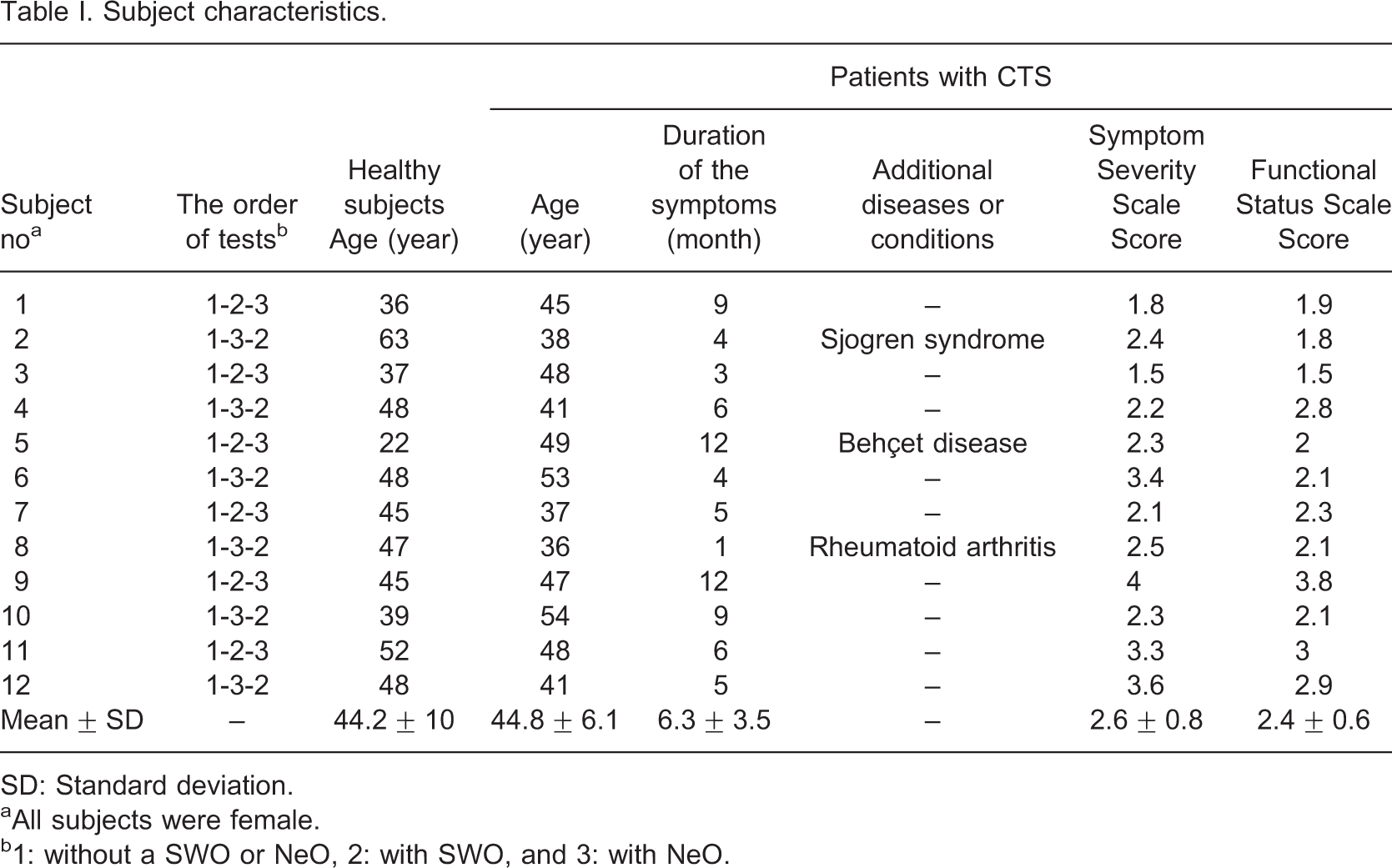
SD: Standard deviation.
aAll subjects were female.
b1: without a SWO or NeO, 2: with SWO, and 3: with NeO.
Test instruments and batteries
Hand function was evaluated with the Jebson Hand Function Test (JHFT). 27 It consists of seven subtests: Writing a sentence (J1), turning over 3 × 5 inch cards (J2), picking up small common objects (J3), stacking checkers (J4), simulated eating (J5), moving empty cans (J6), and moving heavy cans (J7). The components of the JHFT test are shown in Figure 1a.
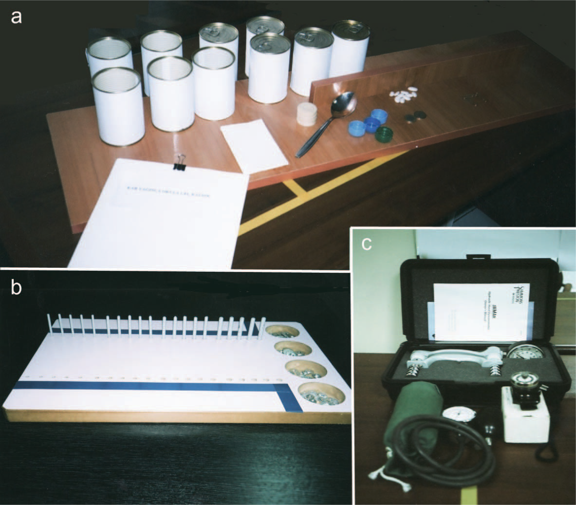
Test instruments and batteries used in the experiments: (a) Jebson Hand Function Test; (b) modified Purdue Pegboard Test; and (c) the instruments for strength measurements.
A modified version of the original Purdue Pegboard Test (mPPT) 28 with 20 holes was used to measure hand dexterity. The mPPT test board with pins on it is demonstrated in Figure 1b.
Grip strength was measured with a new calibrated Standard Jamar Dynamometer (JD) (Asimov Engineering, Los Angeles CA, USA). In the study, the second handle position was used.
A modified, calibrated sphygmomanometer (MS) was used to measure grip pressure.29-31 The method described by Melvin 29 was used to construct the MS. To be able to measure pressure values up to 510 mmHg, adaptation and calibration procedures were applied. The reason for using a MS in the study was to differentiate the effects of squeezing a soft object accommodating to the shape of the hand vs. the rigid handle of the JD.
For measuring pinch strengths, B&L PG-30 (B&L Engineering, Tustin, CA, USA) model pinch gauge pinch gauge was used. Figure 1c shows the test instruments for strength measurements.
Architecture of the NeO control system
The NeO control system is a closed-loop control strategy using positional feedback of the wrist joint. It consisted of three main modules: (i) sensor, (ii) controller containing signal processing and waveform generation, and (iii) amplification of the generated waveforms. The block diagram of the closed-loop controller is shown in Figure 2.
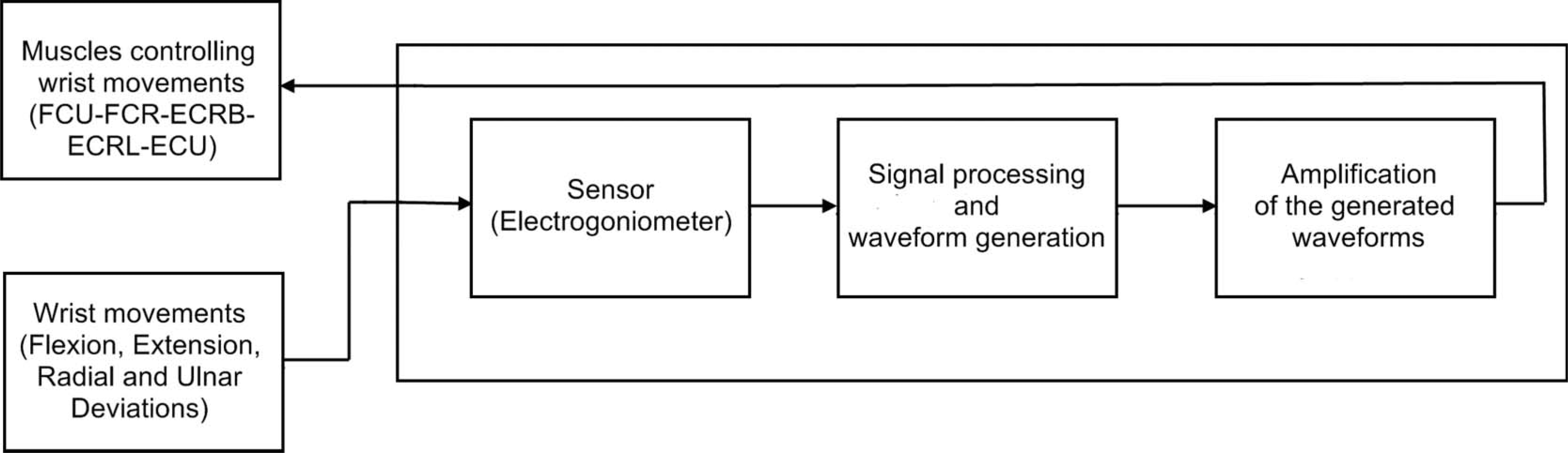
Block diagram of the neuro-orthosis (NeO) control system.
The sensor
Positional feedback was provided with a custom-made electrogoniometer. Biometrics SG65 (Biometrics Ltd., Gwent, UK) or Infrotronic XM65 (Infotronic. Tubbergen, The Netherlands) are widely used strain-gauged electrogoniometers for wrist joint.32-36 The length of the distal block is 55 mm and 60 mm at these models, respectively. When the distal block is placed on the third metacarpal bone over the dorsum of the hand, sometimes it covers not only the whole metacarpal bone in length but also carpal bones and the midcarpal joint. When this happens, the strain sensitive part of the electrogoniometer measures only the angulations of the radiocarpal joint. This is a common situation especially in medium- or small-sized hands. However, the wrist is not a single joint. Instead, it is a complex set of articulated links. 60% of total flexion and 33.5% of total extension at this joint complex occur at the midcarpal joint. 37 Similarly, radial and ulnar deviation movements are a combination of movements at more than one joint. Any sensor to measure wrist movements should consider this complex joint structure.
In this study, a bi-axial potentiometric electrogoniometer measuring the total movement at this joint complex was developed. The components of this sensor are demonstrated in Figure 3. It was calibrated and tested for reliability. The non-repeatabilities for sagittal and frontal planes were 0.53% and 0.7%, respectively, and non-linearities were 0.66% and 1.04%, respectively. The mean error for extension/flexion was 1.07° and for radial/ulnar deviation it was 1.08°.
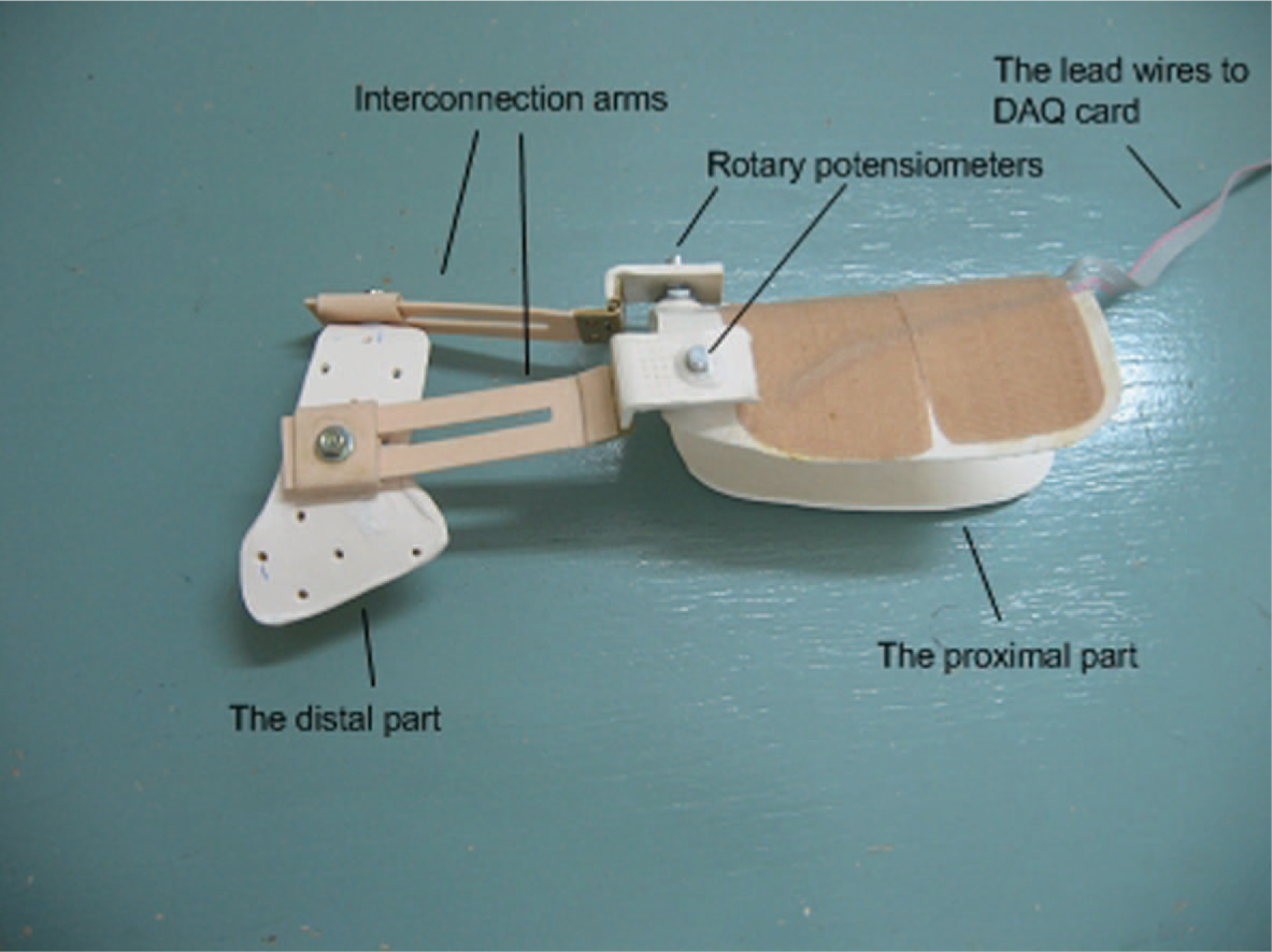
The bi-axial potentiometric electrogoniometer.
The controller
The controller was developed with LabVIEW 6.0 (National Instruments Corporation, Austin, TX, USA). The panel window of the controller is shown in Figure 4. Two data acquisition cards (Iotech, ADAC 5503-HRV) (Cleveland, Ohio, USA) were used. Doublet waveforms (two closely-packed rectangular waves) were used in the experiments due to their less fatiguing and more forceful contraction characteristics. 38, , 39
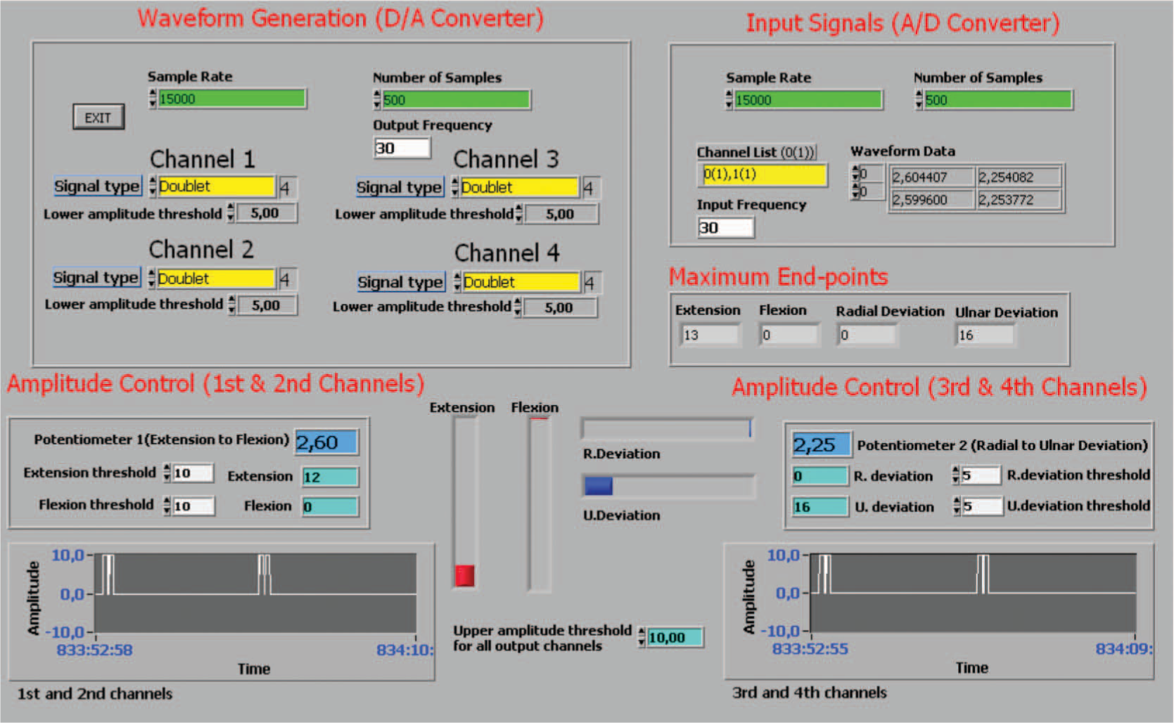
Panel window of the controller.
Figure 5 demonstrates the rule employed by the controller. The strength of the contractions was voltage-modulated. Lower (5 V) and upper voltage (10 V) thresholds were set on the controller. The rate of increase of the stimulation amplitude was proportional to the integral of the angular error e (S = e × Ki and e = θd−θ, where Ki is a constant θd and θ are desired angle and real angle respectively). In this way the larger the error between θd and θ, the faster the amplitude reaches its maximum. The integral controller results in a gradual increase of stimulation amplitude which reduces irritation due to sudden stimulation of the muscles.
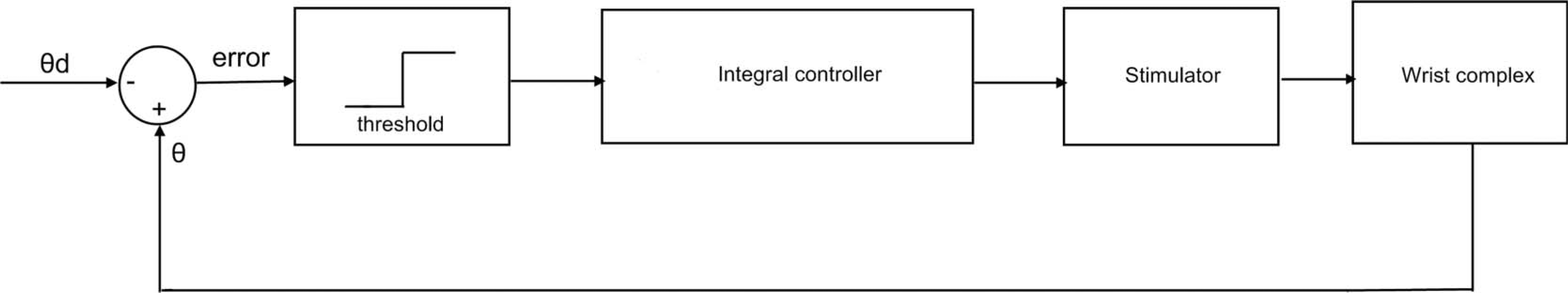
Block diagram of the closed-loop controller.
Amplification circuit
Generated waveforms were amplified to elicit muscle contractions. The circuit was able to deliver 36 mA peak-to-peak (p-p) constant current at 290 Volts (p-p). The patient circuit is isolated from the rest of the circuit for safety. Resulting stimulation pulses are delivered to the motor points of the muscles via small-diameter self-adhesive surface electrodes.
Construction of orthoses
Neutral-position, volar thumbhole SWOs were designed for each subject. Thermoplastic materials (Orfit Classic or Orfit Eco) with a thickness of 3.2 mm were used. Orthoses were strictly controlled to ensure that they did not cause any limitation on the movements of the thumb and MCP joint flexion. Orthoses were fixed to the forearm via Velcro straps. An example of the SWOs used in the experiments is shown in Figure 6.
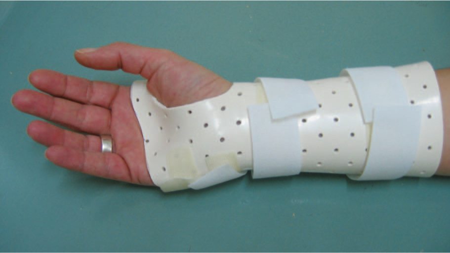
Static thumbhole wrist orthosis used in the experiments.
Test procedures
A training period was allowed and the subjects were familiarized with the test instruments and NeO control system. The tests and measurements were conducted on the right hands of the participants in three different test conditions:(i) With no- orthosis (NO), (ii) with SWO, and (iii) with NeO. The experiments were started with the first test condition to form the baseline measurements and the order of the second and third test conditions were alternated in accordance with the subject number. At the end of the second and third test conditions, the level of discomfort was questioned by means of a 10-cm visual analog scale. There were at least 15-min intervals in between the test conditions. Before starting the experiments, SWOs were constructed and adjustments for the NeO were done respectively. All the experiments, constructions, and set-up lasted about 2½ to 3 h for each volunteer.
Adjustment and adaptation of the NeO control system
During this 30 to 45-min period, motor points and the effective amount of currents (EACs) were determined for each related muscle at the right forearm. EAC was accepted as the amount of current eliciting the desired movement of the stimulated muscle without spreading or minimally spreading to the neighbouring muscles. The forearm was supported on the table while forearm and wrist were in the neutral position. To precisely locate the motor points of the muscles, an isolated probe with a small-diameter tip and an on-off switch was used. Before determining EAC for each movement direction, subjects were informed about the desired movement. The probe was connected to the cathode of the stimulator output. The software control on the computer was adjusted to give constant amplitude doublet waveforms at 30 Hz to the output channel being used. The pulse width was 300 μs. The pulse interval was 5 ms and the period of the doublet stimulation pulses was 40 ms. The aim was to elicit at least two-thirds of the normal range of the dominant movement of the stimulated muscle(s). The intensity of the current was gradually increased until EAC was reached while considering the subject's tolerance of pain due to skin irritation and undesired movements of the neighbouring muscles. Visual and verbal feedbacks were used to decide on the intensity of EAC. The reason for being restricted to some part of the full range of motion was to minimize the effects of the spreading of the current. The higher experimental current intensities strong enough to elicit the full range of the intended motion often resulted in undesired movements at the wrist and/or fingers and disturbing skin irritation. Occasionally, some degree of undesired current spreading was observed even at the intended EAC intensities. However, these were not strong enough to produce sensible joint motion during the adjustment period. The current spreading was more frequently observed in the adjustment of EAC for the extensor carpi radialis longus muscle. When EAC was established, it was kept constant at this point for each output channel and the motor points were marked on the skin. This procedure was repeated for each output channel for 4 movement directions. The following muscles were stimulated: flexor carpi radialis and flexor carpi ulnaris for flexion, extensor carpi radialis brevis for extension, extensor carpi ulnaris for ulnar deviation, and extensor carpi radialis longus for radial deviation. During experiments with NeO system, electrodes were placed on previously localized motor points. An elastic bandage was wrapped around the forearm. This was done to prevent the loosening and/or movement of the electrodes during the experiments as shown in Figure 7. The electrogoniometer was placed on the bandage and fastened to the forearm via Velcro straps while considering the alignment of the movable arms of the sensor. Limits of motion were separately set to 10° in flexion and extension and 5° in radial and ulnar deviation movements. All electrode cables were positioned in a way not to cause any limitation to the limb during the experiments.
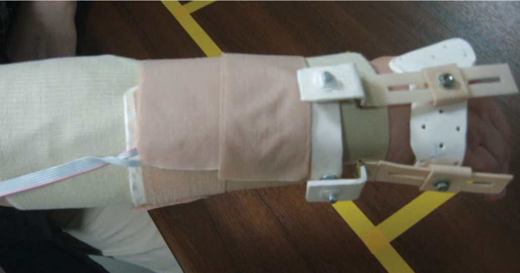
The potentiometric electrogoniometer and the elastic bandage placed over the electrodes.
Application of the test instruments and batteries
Tests were applied in the following order: mPPT, JHFT, grip pressure, grip strength, and pinch strengths measurements. During the first subtest of mPPT, subjects were asked to take a pin and insert it into the holes at the right side of the board. The time required to complete all 20 pins was the score of this subtest. However during the experiments with NeO, this subtest was conducted in two stages. For the first (OFF) stage, the stimulator appeared to be functioning with the lights indicating the presence of the current at each output channel. But the connections from the output terminals of the data acquisition cards to the amplification circuit were disconnected. So there was actually no current flow to the electrodes. At the second (ON) stage, all electrode output channels were re-connected and the subjects were exposed to stimulation pulses. The maximum end points in four movement directions during OFF and ON stages were recorded. In the second subtest, after a pin was placed in the same way as the unilateral test, a washer in the same cup was placed over this pin. The total number of pieces assembled in 30 sec was the score of this subtest.
JHFT was done according to the standard test procedure described by Jebson et al. 27 All subtests were timed. Subjects were instructed to do the function and dexterity tests as fast as possible. In Figure 8, a subject doing the ‘writing a sentence’ subtest with the NeO is seen. Figure 9 shows the implementation of the ‘moving empty cans’ subtest with a SWO. During strength measurements standard protocol described by Mathiowetz et al. 40 was used and the mean of three trials was accepted as the test result. The strength measurements were done by alternating the hands and allowing at least 15 sec between each experiment to alleviate the effect of the fatigue. Lateral, palmar, and tip-to-tip pinch strengths were measured. Figure 10 demonstrates a subject doing the grip strength test with the NeO.
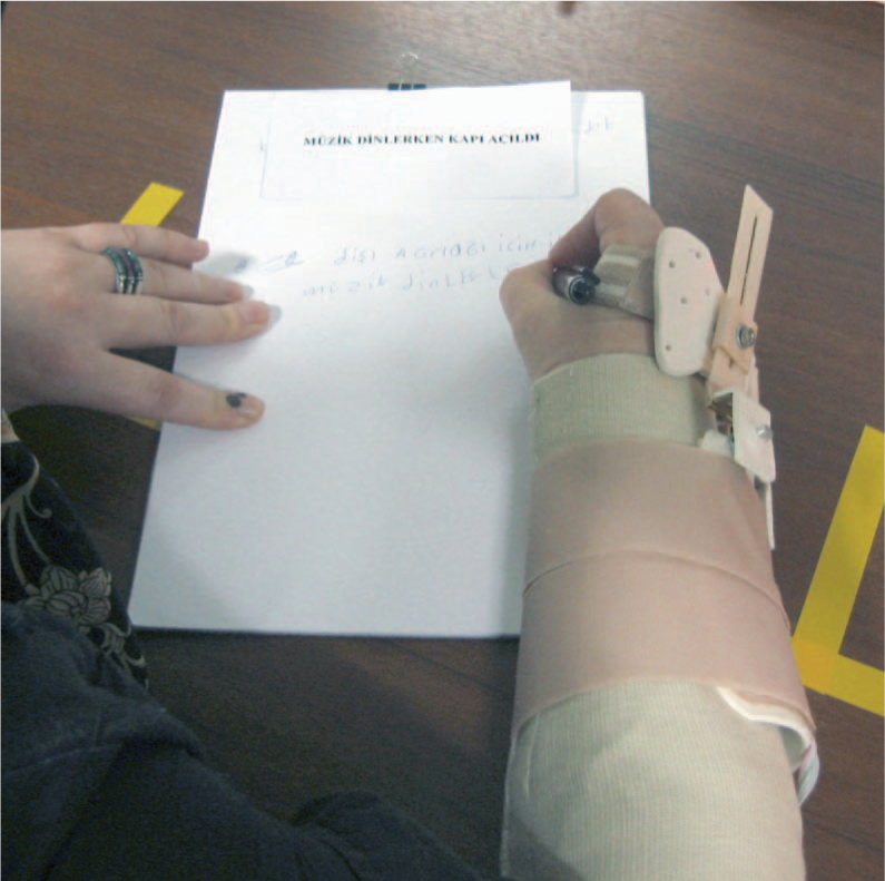
‘Writing a sentence’ subtest of JHFT with the NeO.
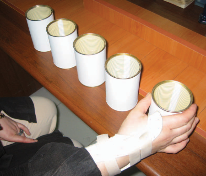
‘Moving empty cans’ subtest of JHFT with SWO.
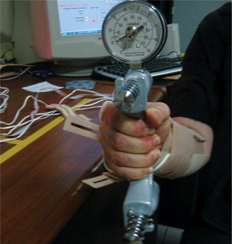
Grip strength measurement with the NeO.
Data analysis
Means and standard deviations for each test condition were calculated. To make comparisons among the three test conditions (NO, NeO, SWO) within the same subject group, relative changes were used instead of absolute values for normalization purposes. The normalization was needed to introduce a relatively patient-independent measurement method since there were significant individual differences in the test results through all the test conditions. The relative change is represented in terms of percentage taking the NO test condition as the basis for each test. Therefore, 2% changes, one for the SWO and one for the NeO test conditions were computed to reflect the relative changes. These relative changes were directly used in t-tests by accepting the baseline measurements (NO test condition) as 0. Parametric tests were used since most of the converted data conformed to normal distribution. Secondly, another comparison of the test means was made between the same test conditions of the two subject groups. It was done to determine whether there were any disease specific effects of each control strategy. This time direct measurement values were used. The levels of discomfort with the SWO and the NeO were also compared within and between the subject groups. The maximum angles at ON and OFF stages during the implementation of the first subtest of the mPPT were also analysed. SPSS-15 (SPSS Inc., Chicago, IL, USA) statistical analysis software was used for the calculations.
Results
Test results of patients with CTS
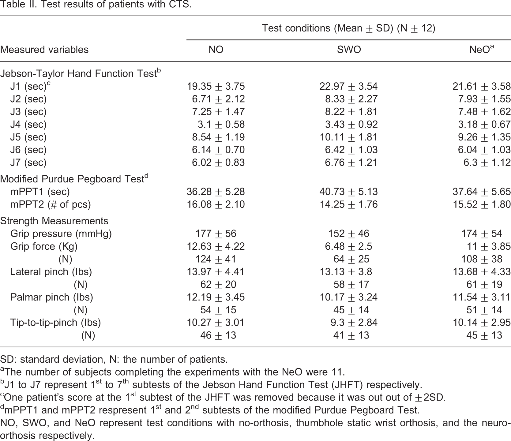
SD: standard deviation, N: the number of patients.
aThe number of subjects completing the experiments with the NeO were 11.
bJ1 to J7 represent 1st to 7th subtests of the Jebson Hand Function Test (JHFT) respectively.
cOne patient's score at the 1st subtest of the JHFT was removed because it was out out of ±2SD.
dmPPT1 and mPPT2 respresent 1st and 2nd subtests of the modified Purdue Pegboard Test.
NO, SWO, and NeO represent test conditions with no-orthosis, thumbhole static wrist orthosis, and the neuro-orthosis respectively.
Test results of the healthy subjects
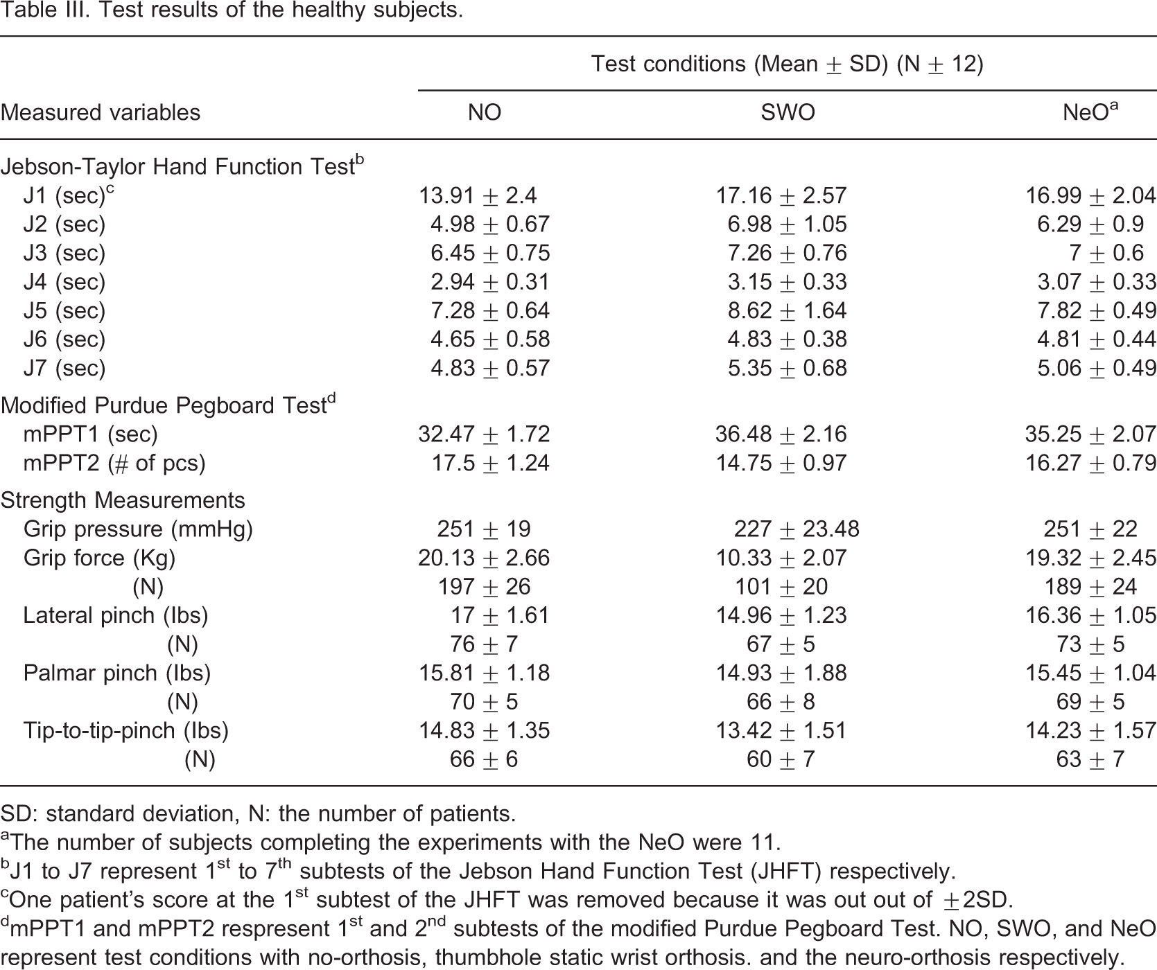
SD: standard deviation, N: the number of patients.
aThe number of subjects completing the experiments with the NeO were 11.
bJ1 to J7 represent 1st to 7th subtests of the Jebson Hand Function Test (JHFT) respectively.
cOne patient's score at the 1st subtest of the JHFT was removed because it was out out of ±2SD.
dmPPT1 and mPPT2 respresent 1st and 2nd subtests of the modified Purdue Pegboard Test. NO, SWO, and NeO represent test conditions with no-orthosis, thumbhole static wrist orthosis. and the neuro-orthosis respectively.
The comparison of test means between the subject groups (Independent samples t-test)
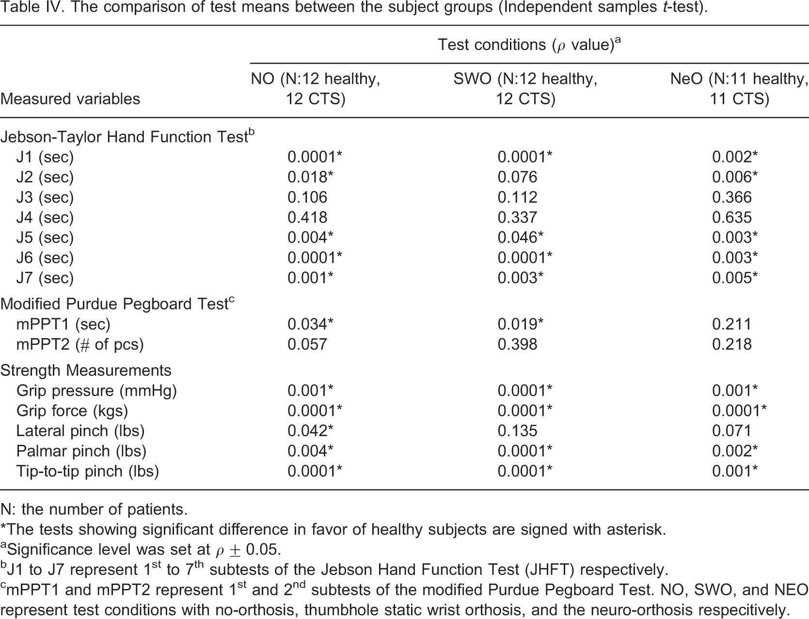
N: the number of patients.
∗The tests showing significant difference in favor of healthy subjects are signed with asterisk.
aSignificance level was set at ρ ± 0.05.
bJ1 to J7 represent 1st to 7th subtests of the Jebson Hand Function Test (JHFT) respectively.
cmPPT1 and mPPT2 represent 1st and 2nd subtests of the modified Purdue Pegboard Test. NO, SWO, and NEO represent test conditions with no-orthosis, thumbhole static wrist orthosis, and the neuro-orthosis respecitively.
The comparison of the test conditions in the group of patients with CTS (NO-SWO and NO-NeO: One-sample t-test; SWO-NeO: Independent samples t-test)
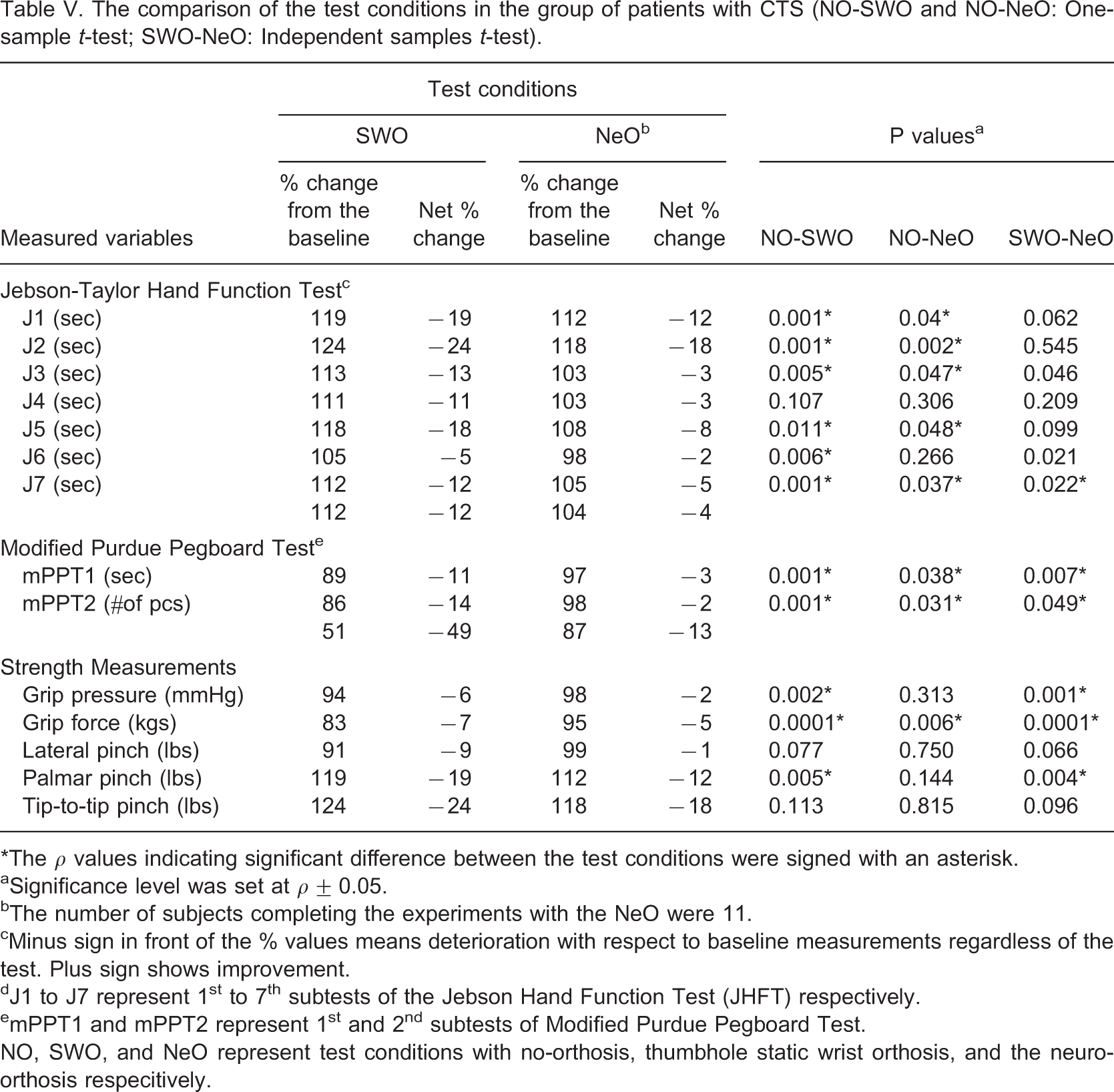
∗The ρ values indicating significant difference between the test conditions were signed with an asterisk.
aSignificance level was set at ρ ± 0.05.
bThe number of subjects completing the experiments with the NeO were 11.
cMinus sign in front of the % values means deterioration with respect to baseline measurements regardless of the test. Plus sign shows improvement.
dJ1 to J7 represent 1st to 7th subtests of the Jebson Hand Function Test (JHFT) respectively.
emPPT1 and mPPT2 represent 1st and 2nd subtests of Modified Purdue Pegboard Test.
NO, SWO, and NeO represent test conditions with no-orthosis, thumbhole static wrist orthosis, and the neuro-orthosis respecitively.
The comparison of the test conditions in the healthy subjects group (NO-SWO and NO-NeO: One-sample t-test, SWO-NeO: Independent samples t-test)
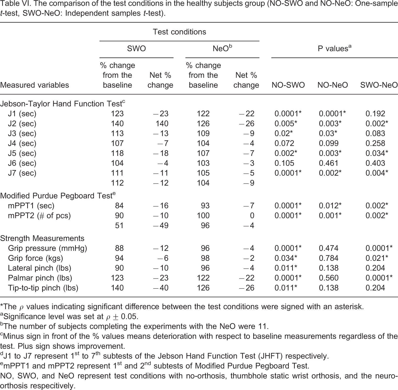
∗The ρ values indicating significant difference between the test conditions were signed with an asterisk.
aSignificance level was set at ρ ± 0.05.
bThe number of subjects completing the experiments with the NeO were 11.
cMinus sign in front of the % values means deterioration with respect to baseline measurements regardless of the test. Plus sign shows improvement.
dJ1 to J7 represent 1st to 7th subtests of the Jebson Hand Function Test (JHFT) respectively.
emPPT1 and mPPT2 represent 1st and 2nd subtests of Modified Purdue Pegboard Test.
NO, SWO, and NeO represent test conditions with no-orthosis, thumbhole static wrist orthosis, and the neuro-orthosis respecitively.
Tables VII and VIII demonstrate the maximum angles for the sagittal and frontal planes respectively while the NeO system was ON and OFF. The total movement arc in the sagittal plane was 33 and 58° for the healthy subjects and 27 and 46° for patients with CTS in ON and OFF conditions, respectively. These were 13 vs. 33°, and 22 vs. 28°, respectively in the frontal plane. The maximum angles reached at both conditions were generally higher in healthy subjects. Movements were not strictly limited to preset values and the ulnar deviation was the less limited movement direction with the NeO.
Maximum angles in the sagital plane while NeO system was OFF and ON
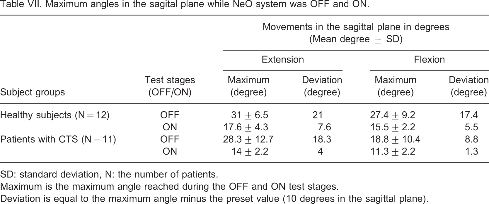
SD: standard deviation, N: the number of patients.
Maximum is the maximum angle reached during the OFF and ON test stages.
Deviation is equal to the maximum angle minus the preset value (10 degrees in the sagittal plane).
Maximum angles in the frontal plane while the NeO system was OFF and ON
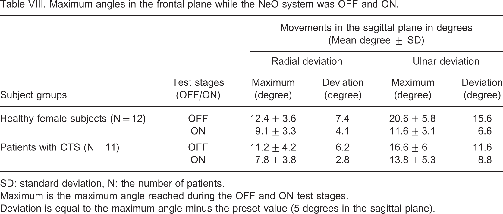
SD: standard deviation, N: the number of patients.
Maximum is the maximum angle reached during the OFF and ON test stages.
Deviation is equal to the maximum angle minus the preset value (5 degrees in the sagittal plane).
Discomfort levels experienced by the subjects during the experiments with SWO and NeO test conditions and t-test results (SD: standard deviation, N: number of patients)
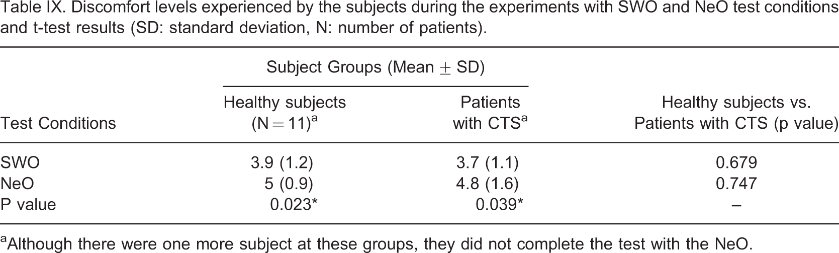
aAlthough there were one more subject at these groups, they did not complete the test with the NeO.
Discussion
We proposed a method aiming to control wrist movements in four movement directions. The basics of functional electrical stimulation were used to limit wrist movements. Although there are complex control systems combining several feedback signals to obtain more precise control over muscles41-44, we preferred to use only position feedback due to its simplicity.
When compared to strain-gauged ones, the custom-made potentiometric electrogoniometer had superior repeatability and reliability characteristics.45-47 However, this sensor should be miniaturized for daily use while preserving its measurement characteristics.
The better performance of the healthy subjects was an anticipated result. The symptoms of CTS result in functional limitations in time. In the study, the mean duration of the symptoms was about 6 months and patients generally reported moderate involvement (about 2.5 on a scale of 1–5) in symptom severity and functional status scales. Although almost all strength measurements were significantly better in the healthy group, this was not true for all function and dexterity tests. Since function and dexterity are not solely dependent on the strength, they can be compensated to some degree.
Both control strategies resulted in limitations on many of the measurements. These limitations were expected since any additional material on the hand and/or any limitation at a joint can hinder the performance of the hand. Although, previous studies generally support the idea that WOs limit hand function and dexterity, there are conflicting results about their effects on hand strength. 20 In most of these studies, subjects used their orthoses for pain relief. It is believed that if WOs provide pain relief, they can immediately improve hand function and strength. However, the main reason for using WOs in CTS differs. 2, , 18, , 19 Pain relief can be provided, but it cannot be an immediate result. SWO resulted in an average of 16% decrease in strength tests in both groups compared to 8% with the NeO. This can be traced to the absence of the rigid part of SWO on the volar aspect of the hand and the allowed movement interval in the wrist with the NeO. While subjects wear SWOs, MS may be a more suitable instrument than a standard JD to obtain an idea about the grip strength. Considering the percent changes from the baseline, the total deviations for SWO and NeO test conditions were lower in the group of patients with CTS. NeO resulted in less limitation compared to SWO in terms of number of significantly different tests in both groups. The comparison of SWO and NeO test conditions produced significant differences in only six tests in the CTS group and eight in the healthy group in favour of the NeO. It can be concluded that both control strategies have less limiting effect on previously diminished functions. Patients probably have a lower performance limit at a specific degree of involvement and any additional limiting factor can cause less disruption.
NeO system was not able to strictly limit the wrist movements to preset values. This can be traced to the following factors: the nature of the test (timed test); the inadequate stimulation intensity and; the time delay between the initiation of the positional change and the contraction of the muscle. The resulting range of motion was still in the safe region in terms of CTP. 10, , 12-14, 16 NeO was more effective in limiting the movements in the sagittal plane. During the adjustment period, the isolation of extensor carpi radialis longus muscle was generally difficult with surface stimulation. When isolated, it required high current intensities and the resulting radial deviation movement was accompanied by some extension. Healthy subjects used a larger range of angular motion compared to the patients with CTS in the first subtest of the mPPT. Patients with CTS probably try to protect their wrists by limiting the movements.
Another problem was the spreading of the stimulation pulses to the neighbouring muscles during the implementation of the tests. This is probably related to the positional alterations between the skin and the motor points of the stimulated muscles. It was reported by two patients with CTS and one healthy subject in tests requiring forearm rotation such as the ‘turning over cards’ subtest of JHFT.
Discomfort due to stimulation pulses was common with NeO. At the beginning doublet stimulation pulses were chosen due to their ability to produce more force with less fatigue. However this waveform shape has constant pulse characteristics and the only way to regulate the muscle force is to use voltage modulation. Therefore, the amplification circuit was adapted to produce high voltages. But this time patients felt discomfort due to skin irritation when the amplitude of the stimulation pulses reached their preset peak values. Hence one subject in each group did not finish the experiments. In such applications, pulse width modulation with regular waveforms can be a less disturbing choice.
Conclusion
According to Tables V and VI, the NeO is found to be superior in terms of dexterity, function, and strength both for healthy and patient groups. SWO is a rigid system by its definition. NeO, on the other hand, has no solid limitation on the joints. This may raise the question about its ability to limit the joint movements at the desired levels required for the treatment. Tables VII and VIII illustrate the fact that when NeO system is turned on, a noticeable limitation affect is introduced. This limitation on motion is not as rigid as that provided with a SWO. It is this feature of the NeO that makes dexterity, function, and strength performances be superior while staying within the treatment range of joint angles. Discomfort due to skin irritation and spreading of muscle contraction were the most prominent problems. To alleviate the irritation, current modulated stimulation, instead of voltage modulation, should be investigated. As an alternate method to achieve the same stimulation levels, one can increase the individual stimulation pulse durations instead of the stimulation amplitude. To increase the muscle selectivity, different stimulation techniques can be investigated. Similar movement limitations could be achieved for the treatment of neuromuscular disorders with some modifications of the system. The components of the system should also be miniaturized in order to use it in daily life.