
Abstract
No other previously published studies consider the relative motion of orthotic components positioned on the upper arm and the forearm. This study therefore measured the location and direction of the axis of rotation of an orthotic component fixed to the forearm in relation to an orthotic component fixed to the upper arm, and compared the results with those obtained by palpation. A plane flexion or extension motion of the forearm component in relation to the component on the upper arm can be described as a pure rotation about a fixed centre. However, activation of the biceps or triceps shifts that centre by around 2 cm, due to a displacement of the humerus within the orthotic component on the upper arm. Within a range of approximately 1 cm, the location of the axis of rotation was similar to that obtained by palpation. Neither custom-made plastic/foam orthoses with their hinges aligned to the measured axis, nor orthoses with their hinges aligned to the palpated axis, exhibited any difference in the wearer's comfort. It is concluded that the best choice for the location of the axis of a hinge-type orthosis for the elbow constitutes a compromise between the axes for active flexion and active extension. In view of the large influence that muscle activation has on axis location, errors in the order of 1 cm seem to be negligible when adjusting the hinge of an orthosis in individual cases.
Introduction
An injury of the elbow joint may require temporary guidance and limitation of the range of motion. One frequently used type of orthosis used to achieve this comprises two custom-made plastic/foam components that are fitted to the upper arm and forearm and then joined by a hinge joint. The patient's upper arm and forearm are then effectively connected by two joints, the anatomical elbow joint and the hinge of the orthosis. Unhindered motion of the joint is only possible if the axes of rotation of both joints coincide. If this condition is not fulfilled then either (1) motion is blocked or (2) the orthotic components glide and tilt in relation to the upper arm and the forearm.
Based on anatomical knowledge and professional experience, a certified prosthetist/orthotist (CPO) will determine the location of the axis of rotation by palpation. The palpated points are marked on the skin and the axis of the orthosis is fabricated in such a way that it passes through these landmarks. Despite the careful fitting of the palpated and orthosis axes, occasionally the orthotic components will glide and tilt in relation to the arm. Thus, even after a satisfactory initial fit, the orthosis as a whole may shift proximally or distally during daily use. Alternatively, muscle activation may alter the location of the bones within the surrounding soft tissue and, therefore, in relation to the orthotic components.
To explore the causes of failures, and to suggest potential improvements, the present study developed a method to objectively measure the location and the orientation of the axis of rotation when flexing or extending the elbow. The study did not aim to determine the location and orientation of the axis of rotation of the anatomical elbow joint. Instead, it aimed to describe the relative motion of an orthotic component fitted to the upper arm in relation to a component fitted to the forearm. These components are not rigidly fixed to the bones but are attached in a pliable fashion to the soft tissues surrounding them.
Although the orientation and the location of the axis of rotation of the anatomical elbow joint have previously been studied in vitro (Morrey and Chao 1976; London 1981; Deland et al. 1987; Bottlang et al. 2000; Duck et al. 2003) and in vivo (Stokdijk et al. 1999), the authors are not aware of any study that has quantified the relative motion of orthotic components.
In a cohort of 10 subjects, the location of an axis of rotation determined by measurement was compared with that obtained by palpation, as performed by experienced CPOs. In addition, the intra- and inter-individual variation that occurs when locating the axis by palpation was documented. In a practical test, four subjects were provided, each with two plastic/foam orthoses which had been custom-made for their right arm – one with the axis of rotation aligned to the position obtained by measurement and the other aligned to the position obtained by palpation. Both function and the wearer's comfort were qualitatively assessed.
Methods
Cohort
The cohort, a sample of convenience, consisted of 10 young, healthy, right-handed adults (eight male, two female), with no previous injury and no prevalent symptoms associated with their arms. Measurement and palpation were performed on their right arms only.
Measurement of the location of the axis of rotation
The subjects sat in front of a table that had been adjusted to a height just below the armpit (Figure 1). The upper arm was equipped with a plastic/foam orthosis component that was 17 cm in length and was fixed to the table. Sliding on the table, the forearm could move unhindered from full extension to about 90° of flexion. During this motion, the palm of the hand rested on the table's surface. Therefore, internal or external rotation of the forearm did not occur. The forearm was equipped with a plastic/foam orthosis component that was 13 cm in length; this was coupled to an xy-digitizer. The xy-coordinates of the coupling point were measured in the course of a flexion – extension motion and were stored in a computer. A circle was fitted to these data points by an iterative algorithm. The midpoint of this circle represents the centre of rotation (CR) of the plane motion performed by the forearm.
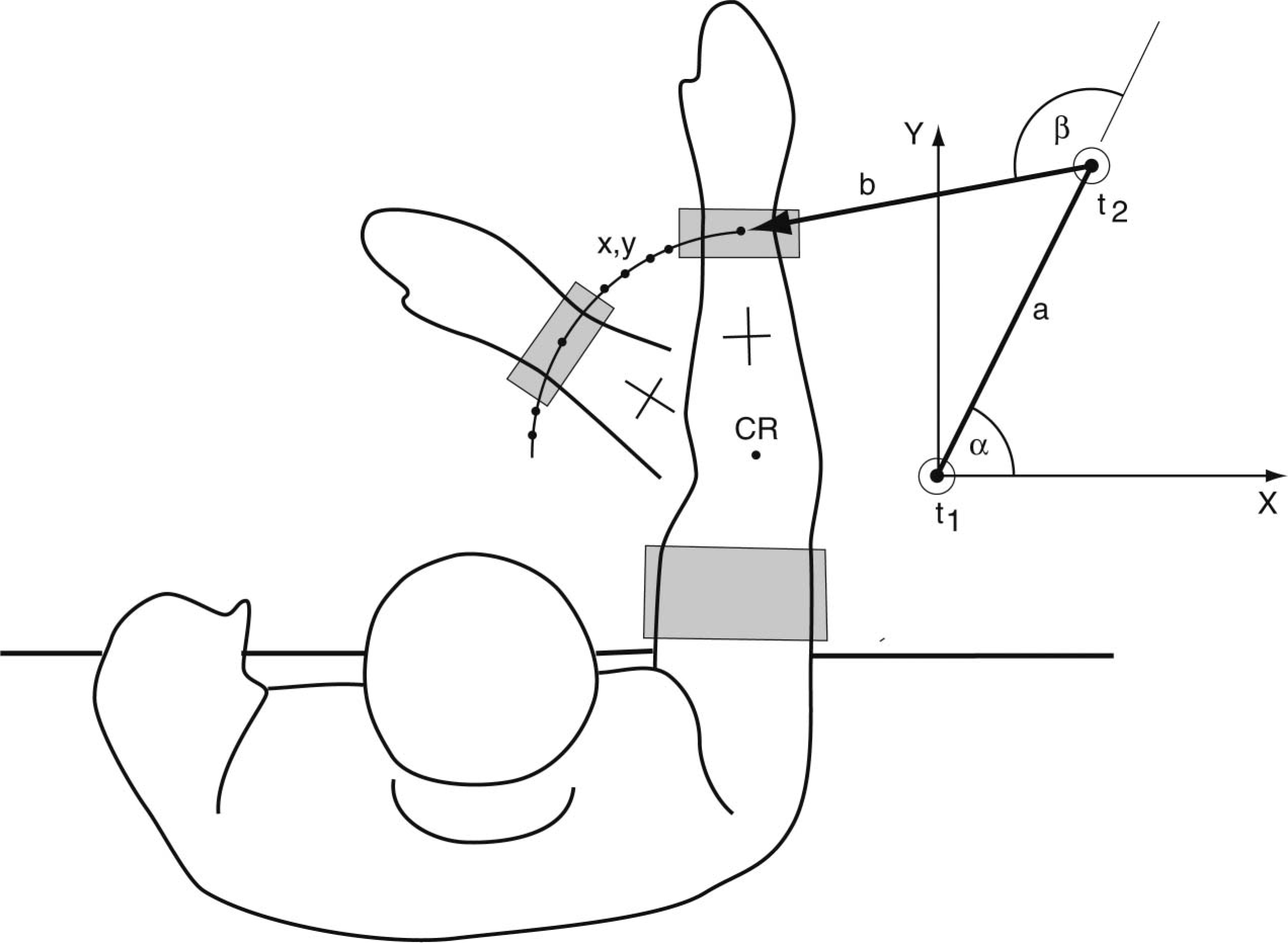
Measurement of the lateral centre of rotation (CR). With the upper-arm orthotic component fixed on a table, the trajectory of a point on the orthotic component fixed on the forearm was measured. A circle was fitted to the data points. Its midpoint CR was marked on the lateral aspect of the elbow. The xy-digitizer consists of two angle transducers, t1 and t2, which are connected by arm a. The tip of arm b is connected to the orthosis component on the forearm. A crosshair (used to relate repeated measurements of the CR) was marked on the forearm.
With the upper arm still fixed on the table and the elbow held at approximately 45° of flexion, the digitizer was used to transfer the computed xy-coordinates of the CR to the skin on the lateral side of the elbow. This marked point on the skin is termed ‘lateral CR’ in this article. The lateral CR represents the point at which the axis of rotation intersects the skin on the lateral side of the elbow. The 45° flexed posture was chosen to allow the measured and palpated centres of rotation to be compared, as palpation is usually performed in this posture. Had this posture not been used, the movement of the skin that occurs when moving the elbow would have confounded such a comparison.
A digital photograph was taken that showed the lateral CR together with a crosshair, which had been drawn on the forearm prior to the measurement being taken, in order to provide a local coordinate system. One axis of the crosshair was orientated in the proximal-distal direction of the forearm. To quantify intra-subject reproducibility, or to compare the results of measurement and palpation, photos from different trials were digitally superimposed by means of the crosshair (Figure 2); the relative coordinates of the different measurements or the palpations were then read. To allow testing reproducibility on different days, the subjects took care to preserve the crosshair and the marks on their skin from the different trials.
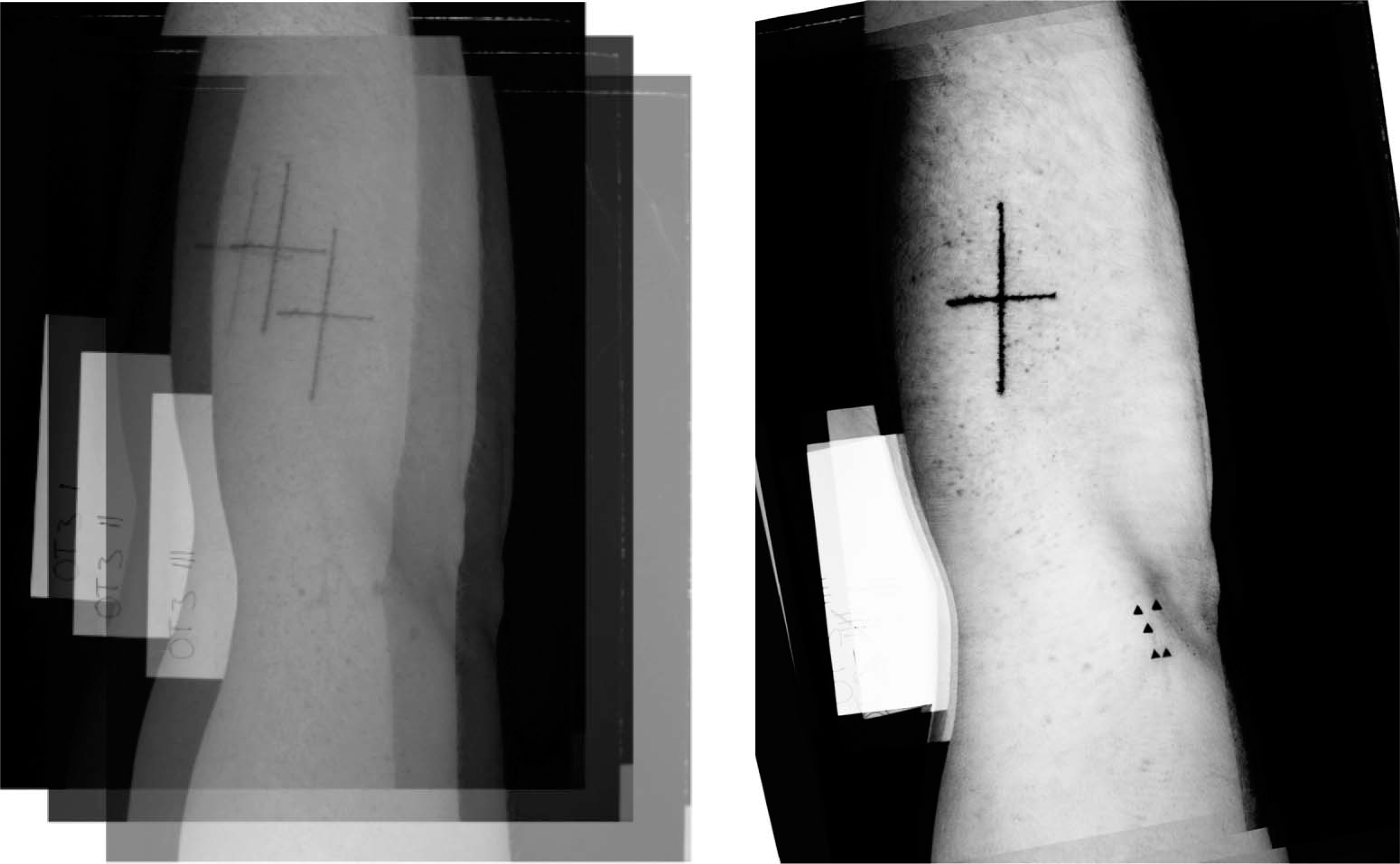
Illustration of the superposition of the digital photographs (left) and resulting image, showing the results of five trials to determine the lateral centre of rotation.
The location of the centre of rotation on the medial side of the elbow (medial CR) relied on the fact that, for a plane motion, the axis of rotation is always orientated perpendicularly to the plane of motion. A laser was mounted on the table that was used for the measurement of the lateral CR. Its beam was orientated perpendicularly to the table surface. From below and through a small hole in the table, a pen could be moved coincidently with the direction of the laser beam. The subject's arm was placed on the table with the lateral CR positioned under the laser beam. The pen was then slid upwards to mark the medial CR.
The xy-digitizer (Figure 1) consisted of two angle transducers, t1 and t2, which measured angles in the range of 0 – 360° in steps of 0.01°. Transducer t1 was fixed at the origin of the xy-coordinate system. Transducer t2 was connected to t1 by lever a; lever b was fixed to transducer t2. Levers a and b were both 200 ± 0.1 mm in length. The xy-coordinates of the tip of lever b were calculated as follows:
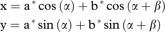
with α being the angle of lever a in relation to the x-axis and β being the angle of lever b in relation to lever a. The angle data from the transducers were transmitted via a serial interface to the computer at a rate of approx. 10 s−1.
Locating the CR by palpation
Based on their professional experience, CPOs located the points at which the axis of rotation was expected to intersect the skin on the medial and the lateral side of the elbow (medial and lateral CR). To this end, with the upper arm at 45° relative to the forearm, the epicondyles were palpated. The subject's elbow was then passively moved in flexion-extension. By this means, the CPO located, between thumb and forefinger, those points of the skin on the lateral and medial side of the elbow that exhibited minimal (ideally, zero) motion. The points were then marked and a digital photograph was taken which showed the lateral CR, together with the crosshair, on the forearm.
To quantify inter- and intra-observer errors when locating the CR by palpation, four experienced CPOs palpated the lateral CR of the same subject five times in a row, without knowing the results of the previous examinations.
Experimental errors
Based on the specifications of the angle transducers, the error of the xy-coordinate measurement was estimated to be smaller than 0.14 mm. When checked against a precisely (±0.01 mm) machined calibration device, the error was, in effect, shown to be lower than this estimate. To check the overall accuracy when fitting a circle to a set of coordinate points, a 90° sector of a precisely machined circle with a radius of 80.0±0.05 mm was traced with the digitizer. The radius of the fitted circle was 80.02 mm; its computed midpoint deviated by less than 0.25 mm from that of the machined one. The error in transferring a computed or palpated CR to the skin mainly results from skin motion, and was estimated from repetitive trials in a pilot study to be ±1 mm. The error in reading relative coordinates from superimposed photos was estimated to be ±0.5 mm.
Results
Description of the motion by a rotation about a fixed CR
In the region of 0 – 90° of flexion, the trajectory of the forearm component measured during a flexion or an extension motion can in very good approximation be described by a circle. In the example shown in Figure 3, the standard deviation (SD) of the data points measured during flexion in relation to the fitted circle was 0.44 mm. The SD of the data points measured during extension was 0.39 mm in relation to the fitted circle. When a circle was fitted to the pooled set of data points measured during flexion and extension, the SD was found to be 2.7 mm.
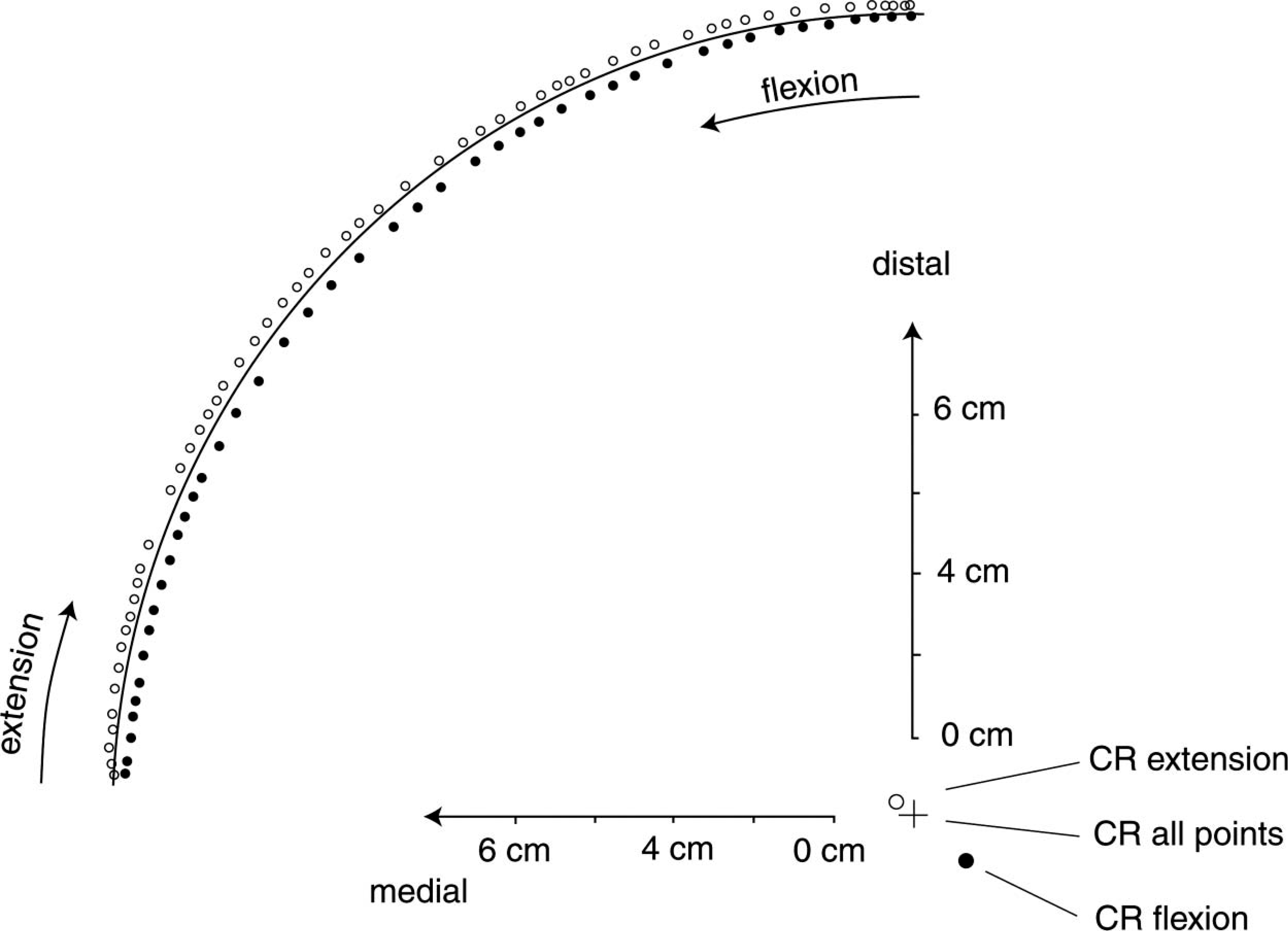
Protocol used to measure an active motion of the right forearm from full extension to 90° of flexion, and back to full extension. Set-up as shown in Figure 1. Full circles: data points measured during flexion. Open circles: data points measured during extension. The midpoints of the circles (centre of rotation (CR)) fitted only to the data points measured during flexion, only to the data points measured during extension or to the pooled set of data points from flexion and extension are shown. In addition to the data points, the contour of the circle fitted to the pooled data set is shown.
Influence of muscle activation
When the forearm was actively moved, the data points taken during flexion followed a trajectory that was distinctly different from that followed during extension (Figure 3). The CR of the flexion data was displaced laterally and proximally in relation to the CR of the extension data. The distance between the two centres was in the order of 2 cm. In contrast, when the forearm was moved passively, the data points obtained while flexing and extending the arm lay on almost identical trajectories and the centres of rotation almost coincided.
As this study focused on the function of hinge-type orthoses with the forearm being actively moved in flexion and extension, it was decided to pool the coordinate data measured during flexion and extension in all subsequent calculations of the CR. One single circle was fitted to this pooled data set. The resulting CR represents a ‘compromise’ in contrast to a description of the motion by the separate centres of rotation for flexion and extension. As mentioned above, in the case of the pooled data, the SD of the data points in relation to the fitted circle was markedly larger than the SD in relation to circles fitted exclusively to the flexion or the extension data.
Repeatability of the CR location identified by measurement
In four subjects the location of the lateral CR was measured five times without removing the orthosis between trials. On average, the SD of the CR location in relation to the geometric centre of the five measurements was 0.3 cm. In three subjects the location of the lateral CR was measured repeatedly on four different days. On average, the SD of the CR location in relation to the geometric centre of the four measurements was 0.8 cm.
Repeatability of CR location by palpation
The lateral CR of one subject was located five times each by four technicians. The intra-observer error ranged between 0.3 and 1.2 cm. In relation to their geometric centre, the SD of the 20 palpated centres of rotation (4 technicians × 5 trials) was 1.0 cm.
Comparison of CR location performed by measurement and by palpation
In 10 subjects, the lateral CR was determined by measurement. Without knowing the result of the measurement, an experienced CPO used palpation to determine the location of the CR. The mean difference between the measured and palpated centres was found to be 1.4 cm (range: 0.3 – 2.7 cm) in a mediolateral direction. On average, the measured CR was found to be shifted medially in relation to the palpated CR. In the proximal-distal direction of the upper arm, the mean difference between the measured and the palpated location was 0.7 cm (range: 0.0 – 3.0 cm). On average, the measured CR was shifted distally in relation to the palpated CR. The distance between the measured and the palpated CR averaged 2.3 cm.
Comparison of orthoses aligned to the measured or palpated axes of rotation
In four subjects (two male and two female), the lateral and medial centres of rotation of the right arm were determined in two ways: (a) by measurement and (b) by palpation. The difference between the measured and the palpated centre locations amounted typically to 1 cm (range 0 – 3 cm). For each subject two different orthoses were custom-made with their plastic/foam components molded from identical plaster casts. The hinges were aligned to the measured or the palpated centers of rotation.
When comparing the two different orthoses during free flexion-extension motions, the subjects noted no restriction of motion and no tendency to block or hinder the elbow joint in the case of either model. In the case of two of the subjects, however, visual inspection showed a minor tendency on the part of the forearm component to tilt in relation to the forearm. The hinges of these orthoses had been adjusted to the palpated axes. When approaching full extension of the elbow, all orthoses showed a noticeable degree of external rotation.
Discussion
Previous studies (Morrey and Chao 1976; London 1981; Deland et al. 1987; Stokdijk et al. 1999; Bottlang et al. 2000; Duck et al. 2003) determining the location and direction of the axis of rotation, relate to the anatomical elbow joint. The majority of these studies were performed on specimens, and aimed to provide basic data for the construction and placement of artificial joints. These studies showed that the motion of the anatomical joint can be described as per the motion of a hinge joint. Within the whole range of motion, helical axes of motion varied in direction by only a small amount. Larger deviations were seen only in cases of injured ligaments (Bottlang et al. 2000).
In contrast to the studies considered above, the present study focuses on the description of the motion of an orthosis component that was fixed on the forearm in relation to a component fixed on the upper arm. The relative motion is regulated by the motion of the anatomical elbow joint and, potentially, by the pliable coupling of the orthotic components in relation to the bones. In view of the practical applications of an orthosis, the motion selected for the location of the axis of rotation was not a free motion but an active, plane motion of the forearm, ranging from full extension to approximately 90° of flexion. This simulates the motion that is observed in real life when picking up a cup of coffee and guiding it to the mouth.
The measurements show that, in isolated flexion or extension, the motion of the forearm can be described as a pure rotation. The CR for flexion differed, however, substantially from the CR for extension (Figure 3). This shift may be explained by the displacement of the humerus in relation to the upper-arm orthosis component that is caused by muscle contraction. If the biceps contracts (flexion), the humerus and therefore the elbow joint shifts laterally. If the triceps contracts (extension), the humerus and therefore the elbow joint shifts medially.
As patients wearing an elbow orthosis perform active motions, the CR of the elbow joint can be expected to migrate in relation to the upper-arm orthostic component, in dependence on the activation of the muscles. In other words, even if the hinge of an orthosis were originally perfectly aligned to the anatomical axis, the elbow joint will be displaced due to muscle contraction. In active use, the anatomical and orthosis axes will no longer coincide and the components will inevitably exhibit some gliding and tilting in relation to the soft tissues of the arm.
The SD of repeated measurements of the lateral CR of 0.8 cm (measurements performed on different days) may be explained by small modifications in the spatial configuration of humerus and adjacent muscles when putting on the upper-arm component. It follows that, in practice, an SD of approximately 1 cm in the CR location on different days is not significant, as the process of putting the orthosis on can be expected to produce variations of comparable magnitude. The bias observed between the measured and palpated lateral CR may be due to the fact that the palpation was performed in passive motion, whereas the measurement was performed in active motion. Both the intra- and inter-individual errors observed when palpating the CR were smaller than the shift of the CR due to muscle contraction.
This study's comparison of custom-made orthoses with hinges that were aligned to an axis of rotation that was determined by palpation with those which had an axis of rotation determined by measurement showed that there was virtually no difference in terms of the wearer's comfort, irrespective of the divergent location of the axes. It follows that, in practice, variations of this magnitude (1 cm, on average) in the placement of the hinge of an orthosis are tolerated without impairing the function. In practice, therefore, it seems that the orthosis ‘adjusts’ itself to some degree. Any remaining discrepancies between orthosis axis and anatomical axis are compensated for by the pliable coupling which links the orthotic components and bones.
In a free flexion-extension motion, external rotation of the forearm can be observed when the arm is close to full extension (Morrey and Chao 1976). In this study, however, the forearm was moved into full extension without simultaneous external rotation occurring while a measurement was made. When the subjects performed free movements with the custom-made orthosis in place, all orthoses were observed to rotate externally by 10 – 15° when approaching full extension. It seemed that, due to its elliptic cross-section, the forearm component transmitted this rotation to the whole orthosis; the upper-arm component then rotated in relation to the humerus and its surrounding soft tissue. The subjects could, however, easily move actively into full extension without external rotation. That is, the subjects could perform a movement identical to that performed during a measurement without any feelings of discomfort.
Conclusions
The plane motion of an orthosis component on the forearm in relation to an orthosis component on the upper arm can be described as a pure rotation about a fixed CR. The CR can be determined by measurement and marked on the skin with a precision of approximately 1 mm. Activation of the flexors or extensors of the elbow shift the CR by approximately 2 cm in relation to the upper-arm orthotic component. As orthoses are moved actively in flexion and extension, it follows that their hinge can only be adjusted to a mean (‘compromise’) location in relation to the axes that are valid, separately, for flexion and extension. The pliable coupling which links the orthotic components and the skeleton then compensates for the remaining misalignment of the axes. When determining the CR, measurement and palpation differed by, on average, 2 cm (the measured CR being shifted medially and distally in relation to the palpated one). When palpating to determine the location of the CR, both the intra- and the inter-observer error were approximately 1 cm. Otherwise identical orthoses with hinges aligned either to the measured or to the palpated axes did not restrict the flexion-extension motion. Nor did they give rise to the subjective sensation that the elbow joint was blocked or hindered. In the four cases tested, the difference between measured and palpated centres of rotation was, on average, 1 cm. It therefore seems that errors of this magnitude in the alignment of the axis of rotation have no practical consequences.
Footnotes
Acknowledgements
The authors gratefully acknowledge the generous financial support that Otto Bock Healthcare, Duderstadt, Germany, provided to this study.