
Abstract
The purpose of the present study was to develop an ankle – foot orthosis (AFO) that satisfies the requirements for an AFO for patients with hemiplegia as determined in a previous study. An oil damper has been introduced as an assistive device. The oil damper provides a resistive moment to plantar flexion of the ankle joint during initial stance on the paretic side. This function improves the insufficient eccentric contraction of the dorsiflexors. The magnitude of the resistive moment generated by this newly developed AFO can be changed easily to adjust its properties in accordance with the requirements of each patient. The mechanical properties of the AFO were measured, and the results showed that the AFO generated a sufficient resistive moment. Hemiplegic gaits with various types of AFOs were assessed, and it was found that the properties of the AFO affected the movements of the ankle, the knee, and the hip joints. The effects of the resistive moment on the alignment of the shank to the floor during initial stance are also discussed. Based on the results of this study, it is concluded that adjustability will be an essential feature for future AFOs.
Introduction
Two types of studies on ankle – foot orthoses (AFOs) have been conducted. One type has focused on the mechanical properties of AFOs, and the other type has focused on the effects of AFOs on pathological gait. Several studies have investigated the effects of the dimensions, materials, and fabrication techniques on the flexibility of shoehorn-type AFOs (Convery et al. 2004; Klasson et al. 1998; Major et al. 2004; Nagaya 1997; Ross et al. 1999; Sumiya et al. 1996a, b). Yamamoto et al. (1993a) measured the mechanical properties of various types of plastic AFOs and compared them.
Several studies have reported the effects of AFOs on pathological gait. Maltais et al. (2001) measured the gait of children with cerebral palsy and found that net oxygen uptake was significantly reduced by wearing an AFO. Kerrigan et al. (1996) proposed the biomechanical efficiency quotient to assess the efficiency of gait with and without an AFO. Park et al. (1997) studied the gait of children with sacral-level myelomeningocele and found that a solid AFO improved the prolonged knee extensor activity evident in barefoot walking. With regard to hemiplegic patients, Lehmann et al. (1987) investigated the effects of an AFO. The walking speed and stride length were increased by the AFO, but knee instability was induced by an improperly adjusted AFO. Thomson et al. (1999) measured the gait of children with low-level myelomeningocele using three-dimensional gait analysis. An AFO reduced the excessive angular displacement in the sagittal plane, but transverse rotation was increased by wearing the AFO. Other studies have investigated the effects on gait of wearing different kinds of AFOs. Hale and Wall (1987) measured the gait with an AFO with Klenzak joints, a shoehorn-type AFO, and the gait without an AFO using a foot switch, and compared them. Diamond and Ottenbacher (1990) measured the velocity, stride length, cadence, and stance phase time of gait when wearing different kinds of AFOs. Carlson et al. (1997) measured the gait of children with cerebral palsy using a three-dimensional gait analysis system. From these kinematic results, differences in gait with and without an AFO were evident, but the effects of various types of AFOs on pathological gait were difficult to demonstrate.
With regard to the kinetic analysis of orthotic gait, McHugh (1999) described the relationship of the interface force between the AFO and the body and the floor reaction force during gait. Abel et al. (1998) generated stick figures showing the force vectors during gait with and without an AFO, and reported that the AFO influenced the magnitude and direction of the force vectors. Hullin et al. (1992) measured the gait of six children with spina bifida and found that the initial ankle joint angle of the AFO and the use of a rocker sole affected the relative position of the force vector to the knee joint. This effect improved the degree of hyperextension of the knee joint. Yamamoto et al. (1993b) measured the resistive moment generated by an AFO during hemiplegic gait using a specially designed experimental AFO. The magnitude of the resistive moment was related to the flexibility of the AFO. The authors found that the flexibility of the AFO affected the gait of hemiplegic patients (Yamamoto et al. 1993c).
Based on results of gait analysis, we identified the desirable properties of AFOs for hemiplegic patients (Yamamoto et al. 1997). The most important function of an AFO was found to be the resistive moment to prevent rapid plantar flexion of the ankle joint during initial stance of the paretic limb. The required magnitude of the resistive moment was more than five times that needed to prevent drop foot during the swing phase. Moreover, it is necessary to adjust the resistive moment according to the requirements of each patient. The initial ankle joint angle at which the resistive moment starts to be developed is also an important consideration and must be adjusted. The authors have developed an AFO that satisfies the above requirements (Yamamoto et al. 1999). A marked improvement in gait was observed when hemiplegic patients wore the newly developed AFO, but a number of problems remained to be overcome, such as its bulky appearance and the complicated fabrication procedure. The purpose of the present study was to develop a new AFO that satisfies the above requirements and addresses the problems that were identified in the previous study. A hydraulic oil damper was used at the ankle joint of the AFO. In the first part of this report, the structure and the mechanical properties of the AFO are presented. Next, the gaits of patients with hemiplegia wearing the new AFO are described.
Structure and mechanical properties of the new AFO
Based on the results of previous studies, the specifications for development were as follows:
The AFO should have an articulated ankle joint and a moderate ability to correct inversion/eversion movements.
The initial ankle joint angle of the AFO should be adjustable in the range of 0–8° of dorsiflexion.
The range of dorsiflexion should be more than 308 from the initial ankle joint angle, taking into consideration standard gait, ascent and descent of stairs and slopes, and squatting.
The AFO should generate no resistive moment to dorsiflexion. The range of plantar flexion should be more than 10° from the initial ankle joint angle. The AFO should generate a resistive moment against plantar flexion. The magnitude of this resistive moment should be adjustable in the range of 5–20 Nm per 108 of plantar flexion.
An ankle joint with a hydraulic oil damper was developed to satisfy these requirements. The appearance of the new AFO is shown in Figure 1a, and a schematic diagram of its function is shown in Figure 1b. The specially designed ankle joint shown in Figure 1c is attached to the lateral side of the ankle joint, with a single-axis hinge joint used on the medial side. Rotational movement of the ankle joint is converted to linear compression of the oil damper through a cam mechanism. The resistive force of the oil damper against compression serves as the resistive moment against plantar flexion of the ankle joint. The initial ankle joint angle at which the resistive moment starts to be developed can be changed by inserting a small part into the bottom of the damper. In the present study, the initial ankle joint angle was set to 0, 5, or 8° of dorsiflexion. The range of motion of the ankle joint is 18° for plantar flexion and 30° for dorsiflexion from the initial ankle joint angle. The ankle joint moves to plantar flexion with resistance and to dorsiflexion without resistance. The amount of resistive force of the oil damper can be adjusted by changing the diameter of the orifice inside the damper. Thus, the magnitude of the resistive moment (i.e. the flexibility of the AFO) can be easily adjusted by rotating a screw at the top of the oil damper, as shown in Figure 1d. The flexibility can be adjusted continuously and is shown on a dial, with 1 indicating maximum flexibility and 4 indicating maximum rigidity. Adjustment can be performed while the patient is wearing the AFO. A small spring is added to the ankle joint to assist smooth toe-off in the late stance phase and to maintain toe clearance during the swing phase. The weight of this newly developed ankle joint is 100 g. The authors have named the new AFO the ‘GaitSolution'.
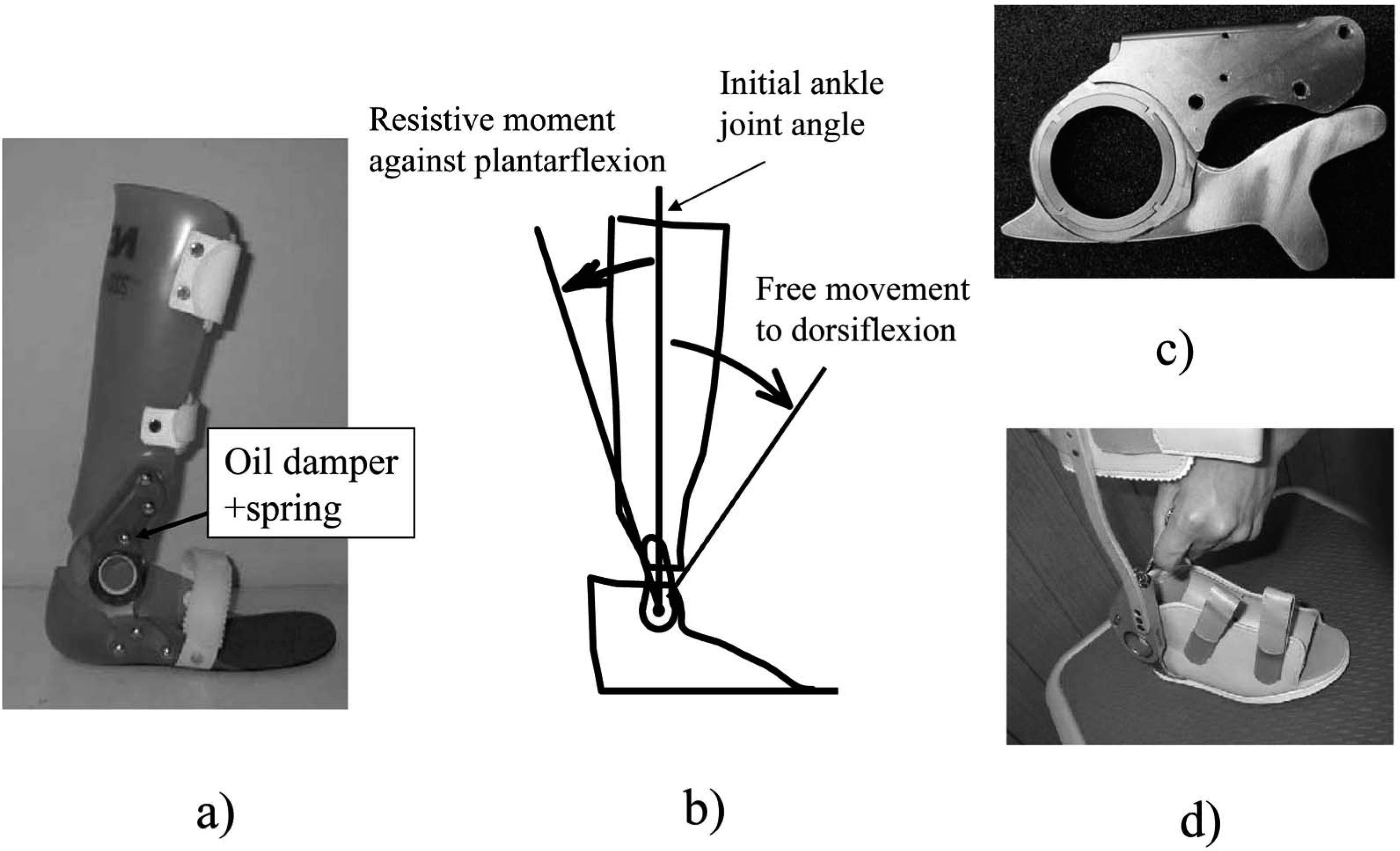
GaitSolution. (a) Appearance. (b) Schematic diagram, Graduate School of International University of Health and Welfare. (c) Ankle joint. (d) Adjustment of the resistive moment by rotating a screw.
The mechanical properties of the GaitSolution were measured. A muscle-training machine was used for measurement as described in a previous study (Yamamoto et al. 1993a). The measurement apparatus is shown in Figure 2. The GaitSolution ankle joint with metal uprights was used to prevent flexion of the plastic parts. Since the resistive force of the oil damper was affected by the compression speed, measurements were obtained at three different speeds. The results are shown in Figure 3. The graph on the left shows the results for the most flexible setting, and that on the right shows the results for the most rigid setting. The horizontal axes indicate the ankle joint angle, the positive value indicates plantar flexion, and the vertical axes indicate the resistive moment around the ankle joint. As shown in the graphs, the GaitSolution generated a resistive moment when the ankle joint was rotated to plantar flexion, and the magnitude of this resistive moment was 5–14 Nm at 10° of plantar flexion. It was found that the magnitude of the resistive moment depended on the selected level of damping, but it seemed to be independent of damping velocity, especially at a higher speed of rigid setting. It was hard to measure the resistive moment at a higher speed because it was observed that the damper hardly moved but the shank of the AFO was significantly deformed at 10°/s and 208/s at rigid setting. It is difficult to determine the actual magnitude of the resistive moment generated by the oil damper during gait because it depends on the displacement and compression speed. However, it can be said that the mechanical properties of the GaitSolution satisfy the specifications for an AFO for hemiplegic patients as described above.
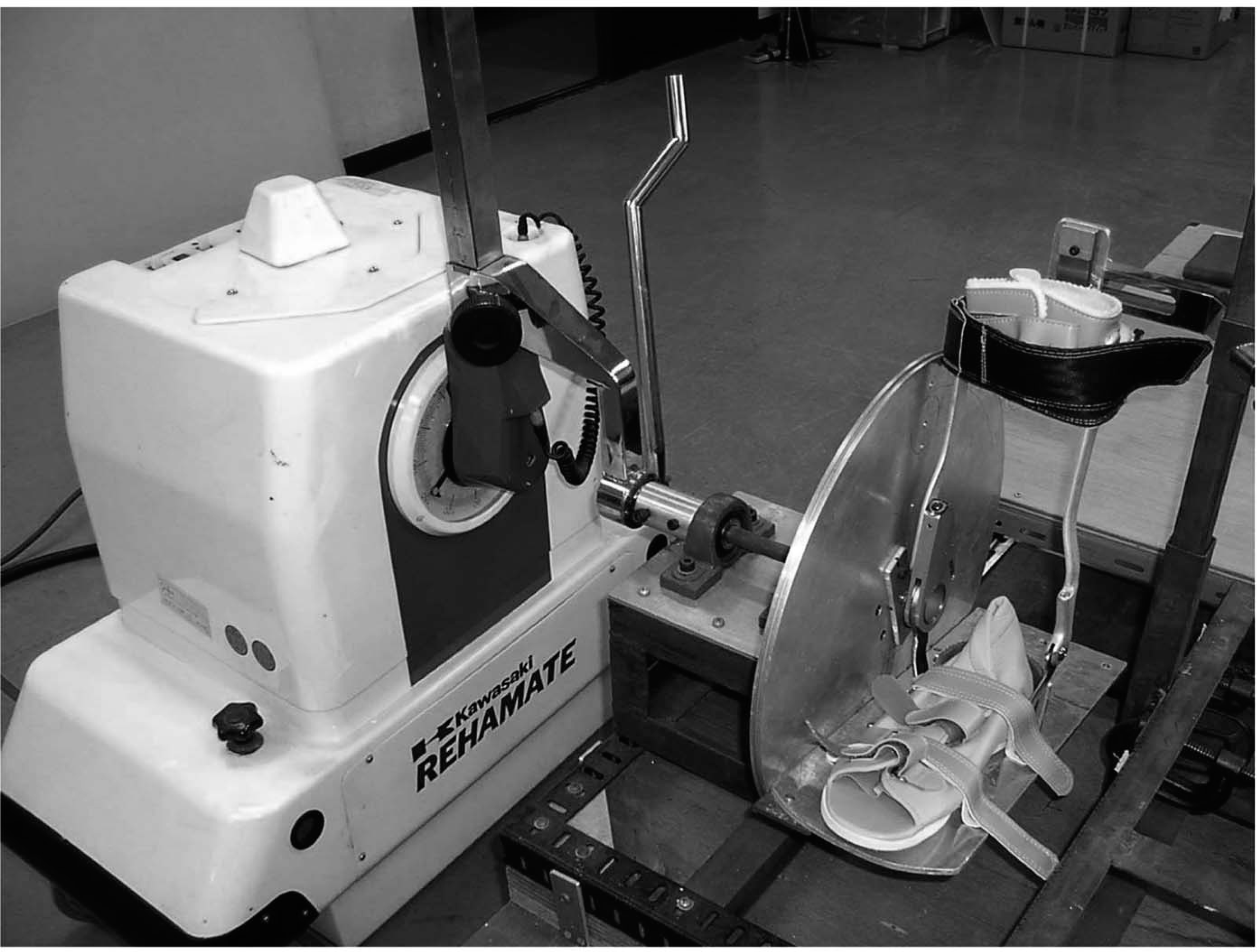
Apparatus for measuring mechanical properties.
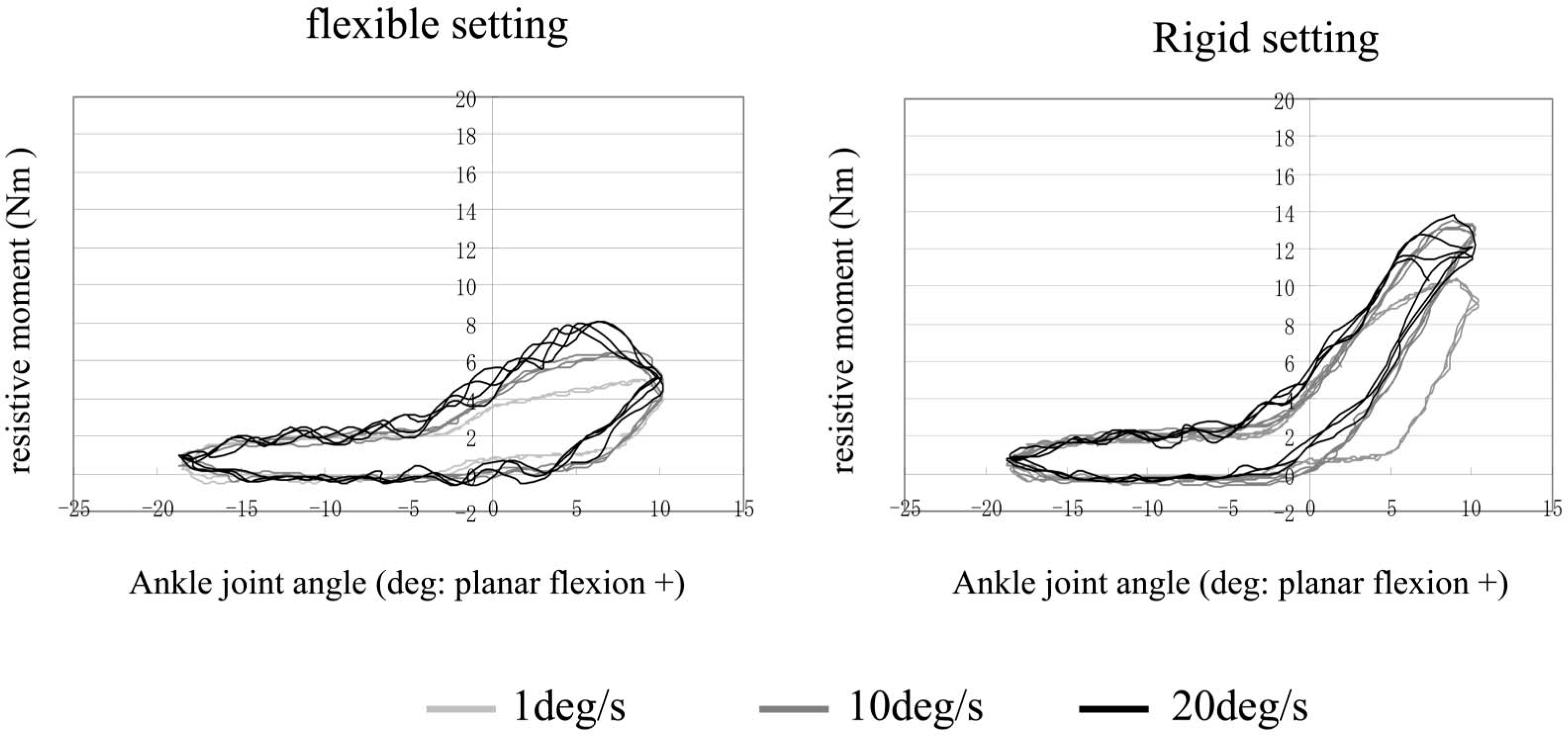
Mechanical properties of the GaitSolution.
Results for gait analysis of patients with hemiplegia wearing the AFO
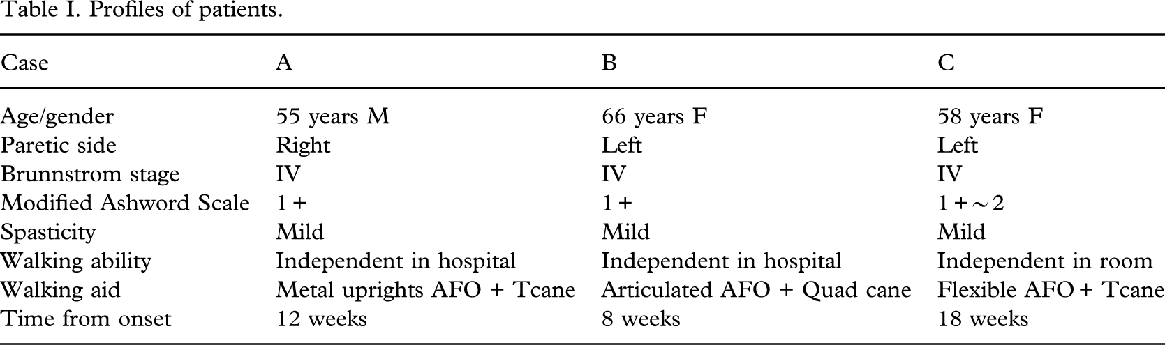
To investigate the effects of the AFO on the gaits of hemiplegic patients, a three-dimensional motion analysis system (VICON512 with Kistler force plates) was used. Reflective markers were attached to the shoulder, the hip (at one-third of the distance between the greater trochanter and ASIS), the knee (at the middle of the patella in the vertical direction and two-thirds from anterior edge in the sagittal plane), the lateral malleolus, and the 5th MP joints on both sides. The gaits were measured while different types of AFOs were worn. Before measurements were obtained, an adequate initial ankle joint angle and an appropriate flexibility of the GaitSolution were selected based on a visual observation of gait. Three trails at a comfortable speed were conducted for each condition. The profiles of the patients are shown in Table I.
Case A
The gaits without an AFO, when wearing an AFO with a plantar flexion stop at 0° of dorsiflexion, and when wearing the GaitSolution were measured. The initial ankle joint angle of the GaitSolution was set at 0° of dorsiflexion. The ankle joints of both AFOs moved freely to dorsiflexion. The mean velocities for each condition were 0.353, 0.408, and 0.451 m/s. Figure 4 shows the angular displacements of the ankle and knee joints on the paretic side. The horizontal axes show the gait cycle starting from the initial stance. The vertical axes show the angular displacement, with positive values indicating flexion and dorsiflexion. Excessive plantar flexion of the ankle joint during the swing phase and hyperextension of the knee joint during the stance phase were observed in gait without an AFO, and these findings were improved by wearing an AFO. When the patient wore the AFO with a plantar flexion stop, ankle-joint motion was restricted and the knee joint flexed at initial stance and then hyperextended at late stance. When the patient wore the GaitSolution, initial flexion of the knee joint was unchanged, but hyperextension was reduced. It has been said that plantar flexion of the ankle joint at initial stance causes hyperextension of the knee joint during the stance phase. This result indicates that adequate resistance to plantar flexion can control the movement of the knee joint during the stance phase. The patient's impression was ‘I prefer the GaitSolution because I can move my ankle joint smoothly with it'.
Profiles of patients.
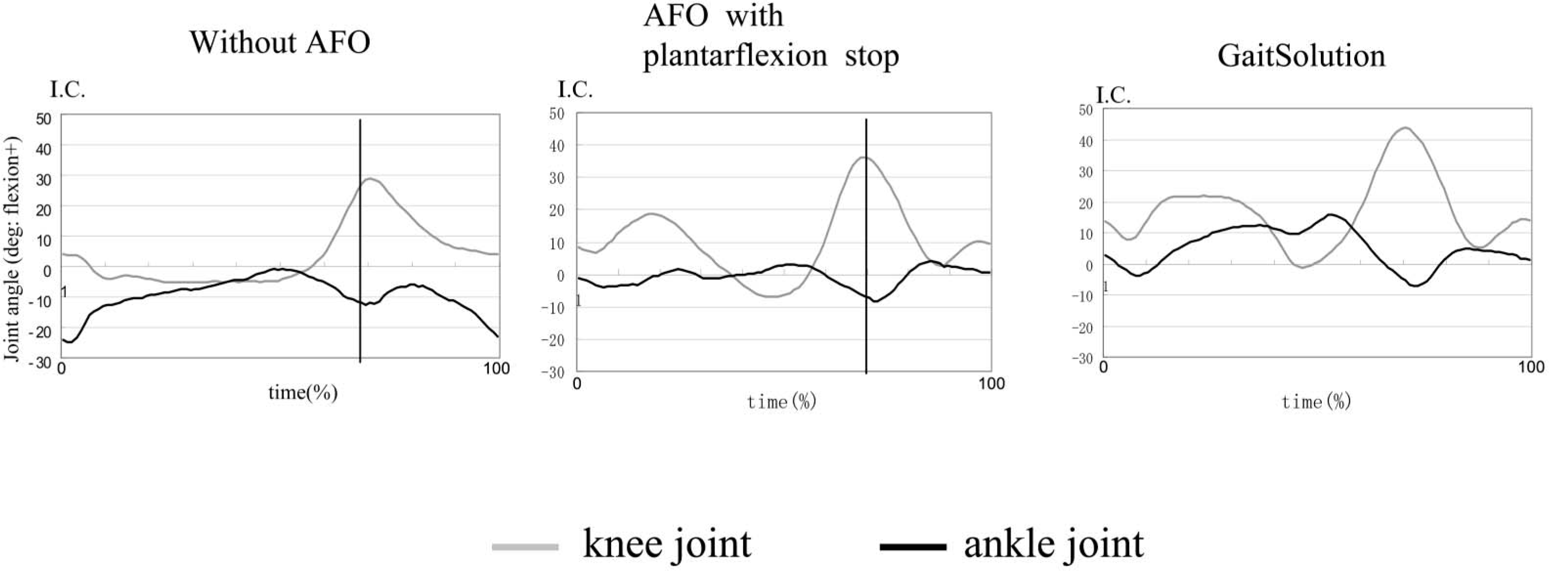
Results of gait analysis. Case A: joint angular displacement.
Case B
The gaits while wearing an AFO with a plantar flexion stop at 5° of dorsiflexion and wearing the GaitSolution were measured. The initial ankle joint angle of the GaitSolution was 58 of dorsiflexion. The ankle joints of both AFOs moved freely to dorsiflexion. The mean velocities for each condition were 0.425 and 0.485 m/s. Figure 5 shows measured stick figures and floor reaction force vectors on the paretic side at the time of initial contact, foot flat, and the time of initial contact of the opposite side. Reflective markers were attached to the ankle joint and fifth MP joint. The floor reaction force vectors are shown using a large scale to indicate the relative positions of the joints to the vectors. Differences were observed in the progression of the hip joint and the centre of pressure. When the patient walked with the AFO with a plantar flexion stop, her hip joint remained backward, and the centre of pressure did not move forward smoothly. Figure 6 shows the joint moment during gait. The horizontal axes show the gait cycle starting from initial contact. The vertical axes show the joint moment, with positive values indicating plantar flexion, and the extension moment. Marked changes were observed in the hip joint moment. A large flexion moment during mid to late stance was observed when the patient walked with the GaitSolution. This means that the hip joint moved forward sufficiently at late stance. Figure 7 shows the forward progression of the centre of pressure during the stance phase. The horizontal axis shows the stance phase time, and the vertical axis shows the position of the centre of pressure. The zero value indicates the position of the ankle joint. The centre of pressure started around the ankle joint and did not move forward when the patient walked with an AFO with a plantar stop. However, the centre of pressure started at the heel and moved progressively forward when the patient walked with the GaitSolution. The patient's impression was ‘When I walked with the AFO with a plantar flexion stop, I felt uncomfortable pressure on my shank, but I did not feel this with the GaitSolution'.
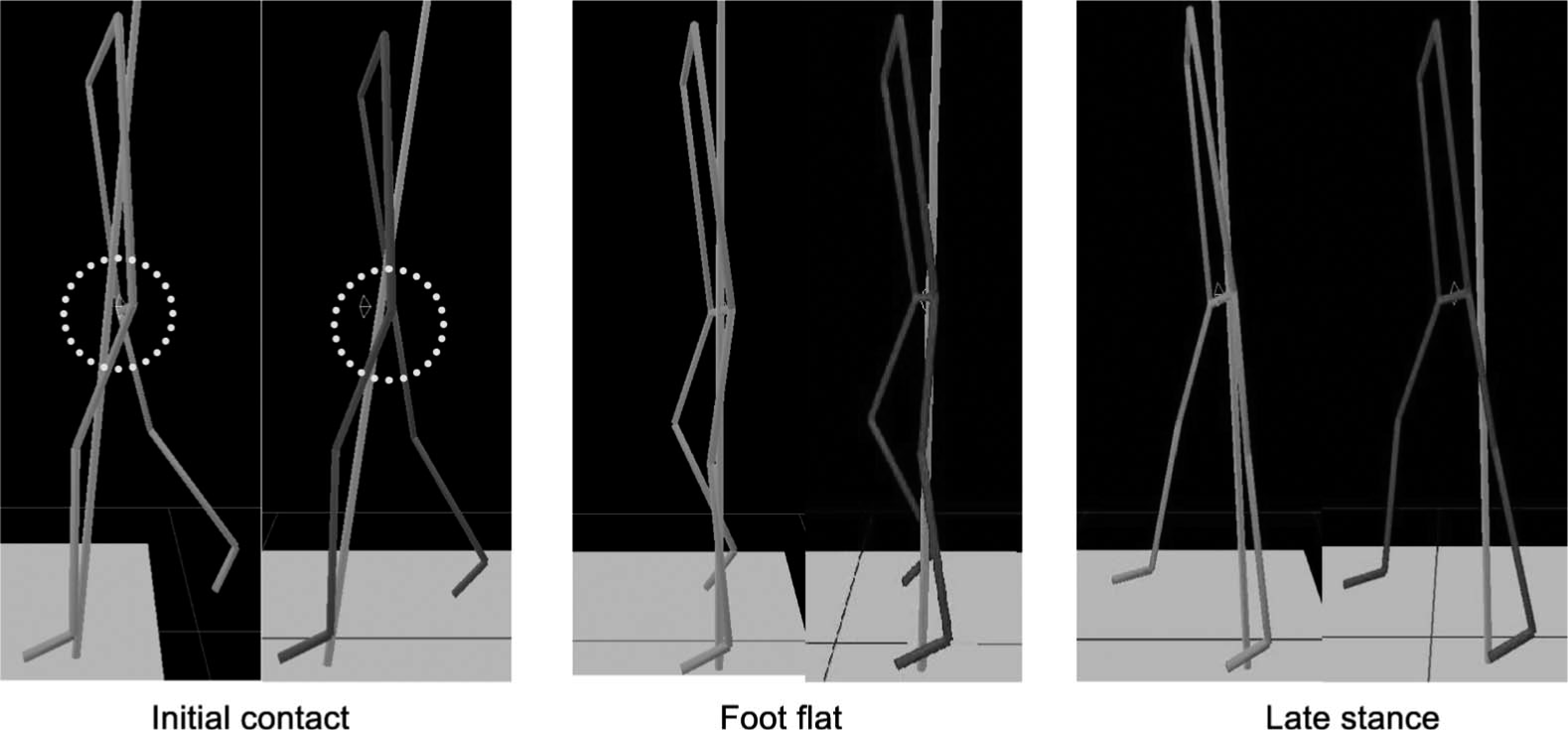
Results of gait analysis. Case B: measured stick figures and floor reaction force vectors. Floor reaction force vectors are shown in large scale to indicate the relative positions of the joints to the vectors. Left: gait with the AFO with a plantar flexion stop. Right: gait with the GaitSolution.
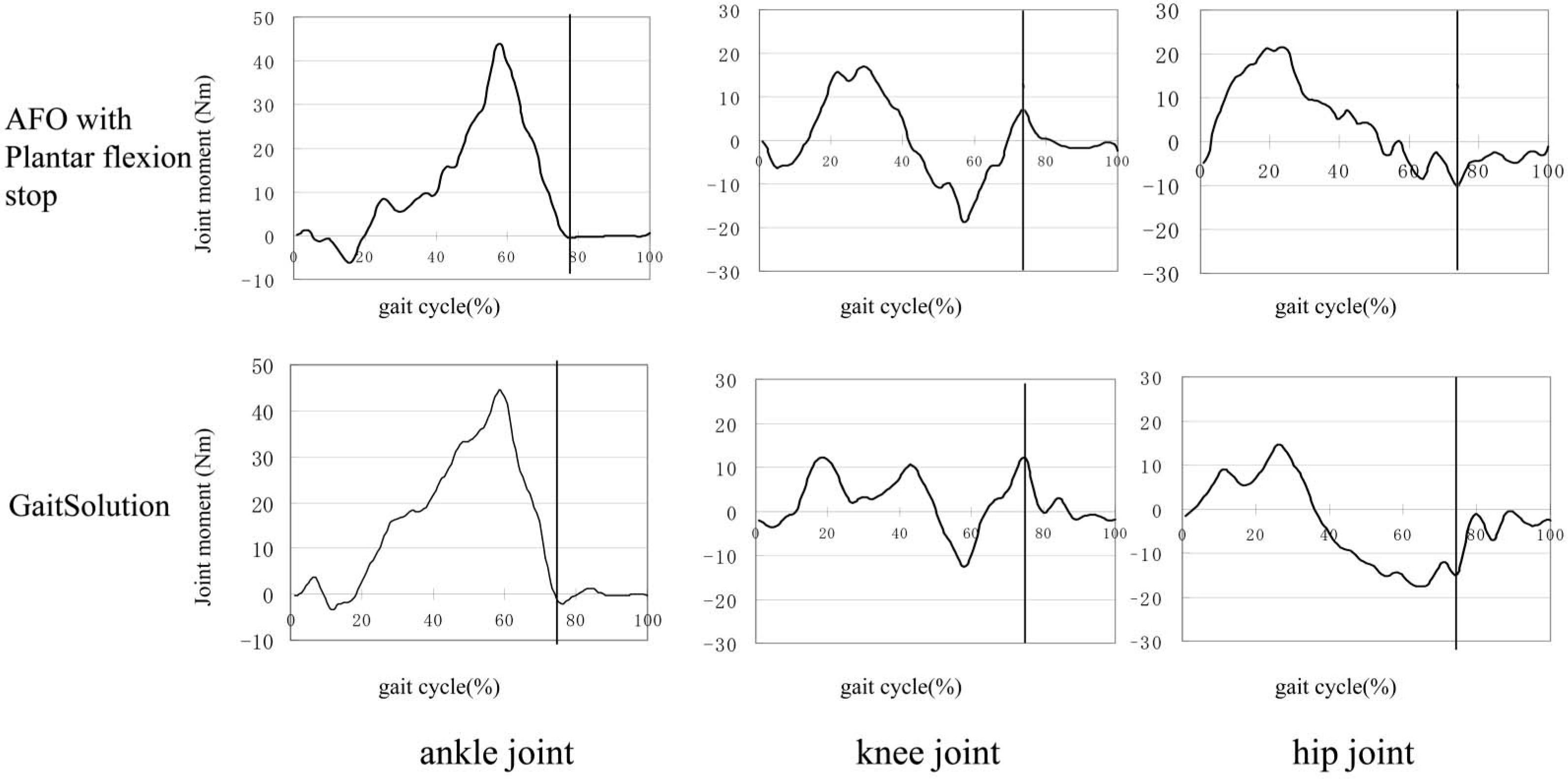
Results of gait analysis. Case B: joint moment.
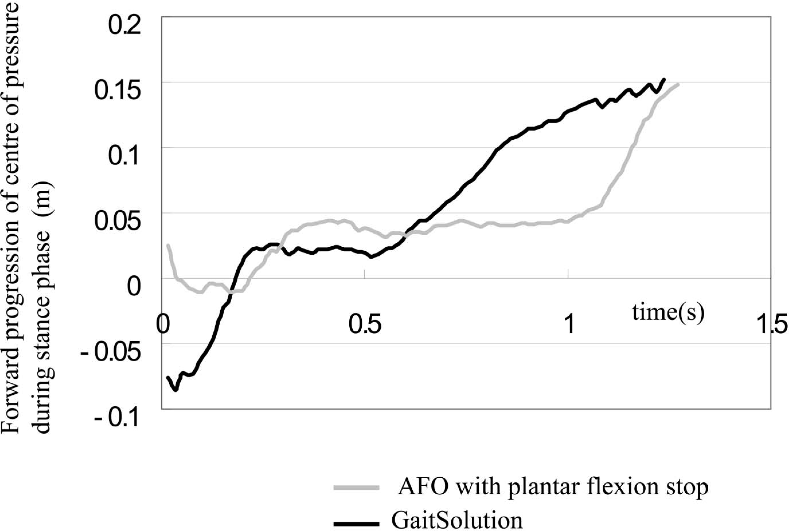
Results of gait analysis. Case B: progression of the centre of pressure.
Case C
One of the greatest advantages of the GaitSolution is that the flexibility can be adjusted easily. Figure 8 shows the angular displacements of the ankle and knee joints when a patient walked with the GaitSolution set to four different degrees of flexibility. Ankle joint movement was restricted at a rigid setting. Greater flexibility resulted in greater plantar flexion of the ankle joint at initial stance and greater hyperextension of the knee joint at mid-stance. According to the patient's impression, the third flexibility setting (3) was the best because the ankle joint moved moderately without excessive extension of the knee joint. The mean velocities were 0.304, 0.370, 0.397, and 0.39 m/s, with the maximum value obtained at the setting preferred by the patient.
Discussion
The results of the present study show that the properties of the AFO affect not only movement of the ankle joint but also the movements of the knee and hip joints. The flexibility of the AFO and the initial ankle joint angle are able to control the alignment of the body to the floor. They also affect the magnitude and direction of the floor reaction force vectors. These are referred to as the indirect effects of the AFO, and such effects are particularly important at initial stance of the paretic limb.
Simplified figures and the floor reaction force vectors at initial stance are shown in Figure 9. From the viewpoint of gait analysis, the muscle activities at initial stance are very important (Perry 1992). In normal gait, a force vector is applied to the heel at initial contact, resulting in plantar flexion of the ankle joint. At the same time, the dorsiflexors work eccentrically to ensure gradual plantar flexion and gradual tibial progression. The knee extensors also operate to ensure femoral progression. Consequently, the knee joint is slightly in front of the ankle joint at the time of foot flat, and the floor reaction force vector passes slightly behind the knee joint. The resistive moment of the AFO helps to compensate for insufficient activity of the dorsiflexors. If the resistive moment is insufficient, the floor reaction force results in plantar flexion of the ankle joint, but the shank does not move forward. Therefore, the knee joint remains displaced backward at the time of foot flat, and the floor reaction force vector passes in front of the knee joint. This results in hyperextension of the knee joint, and patients cannot recover from this situation during the stance phase. A plantar-flexed setting of the initial ankle joint angle results in a similar situation. On the other hand, if the resistive moment of the AFO is excessive, the following situation occurs. The floor reaction force causes plantar flexion of the ankle joint, and the shank moves forward excessively because the ankle joint is rigid. The knee joint moves forward excessively at the time of foot flat, and the floor reaction force vector passes behind the knee joint. This results in instability of the knee joint. The AFO with a plantar flexion stop results in the same situation. Patients try to hold their body backwards to avoid falling. An excessively dorsiflexed setting of the initial ankle joint angle results in a similar situation.
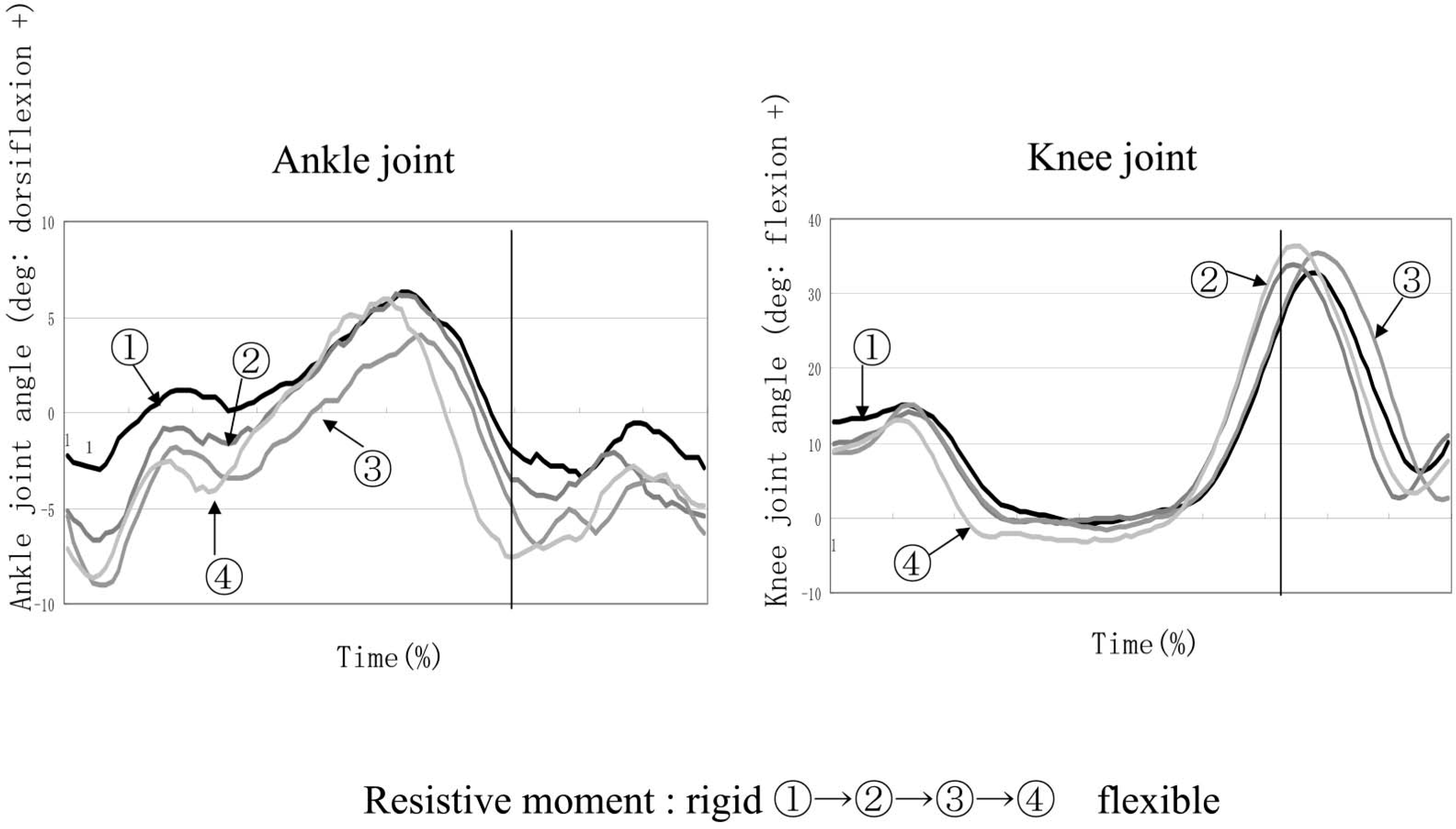
Results of gait analysis. Case C: joint angular displacement for AFOs with different flexibility.
Considering gait with an AFO, it is important to control the alignment of the shank, the thigh, and the upper body to the floor at initial stance. This can be achieved by ensuring a adequate resistive moment and proper setting of the initial ankle joint angle of the AFO. These two factors depend on each patient's condition, such as weight, degree of paralysis, muscle strength of the knee extensors, walking velocity, and so on. Adjustability will be an indispensable feature of future AFOs.
The objective in gait training of patients with hemiplegia is not to achieve normal gait but to achieve the best possible result for the individual patient, in other words, to minimize the hyperextension or instability of the knee joint and to facilitate smooth progression of the body during the stance phase. From this viewpoint, it is important to provide an adequate degree of plantar flexion of the ankle joint at initial stance of the paretic side. The authors feel that the GaitSolution is a useful device for gait training because it prevents rapid plantar flexion but allows gradual plantar flexion. Further downsizing and clarifying the adaptation criteria of the GaitSolution are subjects for future research.
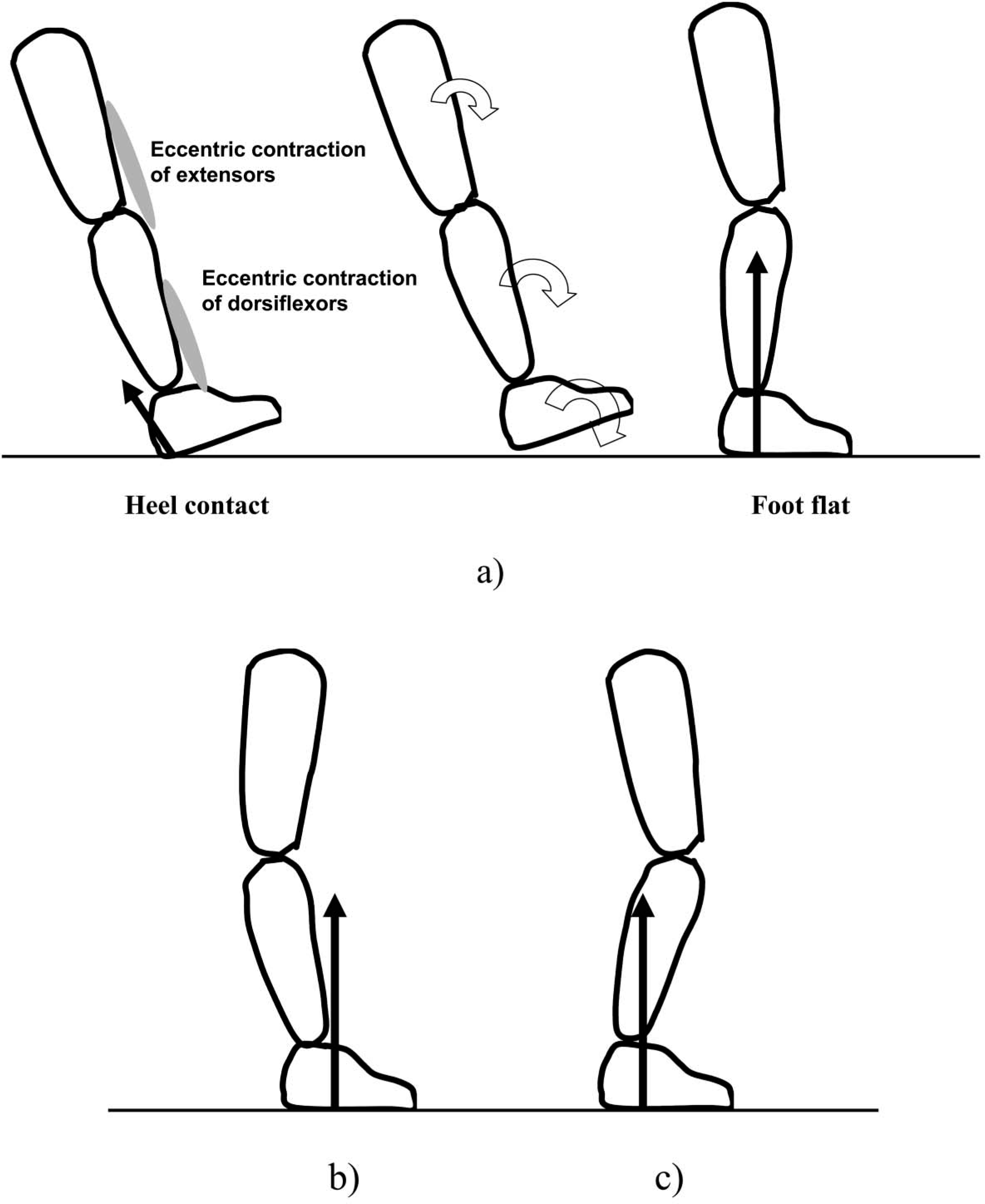
Simplified figures and floor reaction force vectors at initial stance. (a) Normal gait. (b) Insufficient resistive moment. (c) Excessive resistive moment.
Acknowledgements
The authors would like to thank Dr Y. Hayakawa of Kitasato University and the staff of Waseda College of Medical Arts and Sciences for their cooperation in measuring the mechanical properties of the AFO. This study was supported by the New Energy and Industrial Technology Development Organization of Japan.