
Abstract
For the first time, a dynamic beamshaping technology has been utilized for the efficient production of periodic nanostructures on top of AlTiN coating to enable dry machining without costly and environmentally hazardous cutting fluids. First, a variety of periodic nanostructures with periods in a range of 740–273 nm were produced utilizing different wavelengths. Additionally, beamshaping technology increased productivity by 4008% up to 105 cm2 min−1 by shaping the Gaussian beam into a rectangular beam of 500 × 30 µm. To simulate the application load and resulting heat production during manufacturing, friction analysis was performed at room and elevated temperature to 500°C. The analysis revealed a significant reduction in the friction coefficient – up to 27% and 19% at room temperature and 500°C, respectively. The combination of these results demonstrates that the proposed method can be scaled up for the mass production of functionalized machining tools for dry machining.
Introduction
Modification of tribological properties by surface micro and nanostructuring is a popular topic for many research institutions around the world. Optimal surface topography can improve load capacity, wear resistance and decrease friction coefficient compared to the untreated surface under dry, boundary and hydrodynamic lubricant conditions [1-4].
Conventional nanostructuring methods include chemical vapour deposition [5], chemical etching [6], thermal embossing [7], lithography [8], sol–gel [9,10], plasma treatments [11,12], electrodeposition [13,14] or laser surface texturing (LST) [15-17]. However, most of these techniques require several processing steps, chemicals or too long processing times to be implemented in an industrial environment. Among these, LST offers a flexible, fast and environmentally friendly method for high-quality fabrication of desired micro and nano topography with high precision on a large variety of materials [1,18]. LST has been widely implemented for the improvement of tribological properties of mechanical components, including bearings [19], piston rings [20], facing seals [21] and cutting tools [22].
Typical surface topography of laser-treated surfaces improving friction properties is composed of arrays of micro-dimples [23] or laser-induced periodic surface structures (LIPSS) with spatial periods in the sub-micrometre range, which are formed in a ‘self-ordered’ way during the laser irradiation of the surface [24,25]. The great flexibility and variability of produced LIPSS and ripple structures allow a simple and robust way for surface nanostructuring to improve tribological performance [25].
Despite the demonstrated capability of lasers to produce functional friction-reduction surfaces, the production speed of LIPSS-based functional surfaces is still low with respect to many industry standards. Generally, throughputs only up to a few cm2 per minute are reached by conventional single-beam approaches [25]. However, recently demonstrated high-power ultrashort laser systems [26] open possibilities to upscale standard single-beam methods towards multi-beam simultaneous fabrication for fast rapid large-scale surface nanostructuring [27-29]. An alternative can be dynamic beamsplitting [30] or large-beam direct laser interference patterning [31,32], which can also efficiently utilize high-power laser systems or precise fabrication of functional nanostructures.
In industry, the suitable material for a protective barrier against wear is titanium nitride (TiN) based coatings. The main area of using TiN coating is for cutting tools. Enhancing TiN with aluminium, AlTiN coating becomes hard, oxidation resistant and stable in extreme cutting conditions. Compared with, e.g. diamond-like carbon (DLC) coatings, the high friction coefficient of AlTiN coating can be a limit. Due to this reason, a combination of coated tools with cutting fluids is commonly used. However, cutting fluids are becoming the more evident cost during cutting processes and they are dangerous to the environment [33].
Dry machining with nanostructured cutting tools has a big potential to replace the use of environmentally hazardous cutting fluids. Additionally, despite the fact that cutting temperature has a major effect on tool wear and durability [34], the complex, comprehensive analysis simulating the working load and especially the temperature of cutting tools is still lacking.
Thus, the objective of this work is to investigate the influence of different kinds of LIPSS nanostructures on the tribological performance in dry conditions of AlTiN coating deposited on a 1.2379 tool steel substrate. To investigate different designs of LIPSS, ultrashort laser systems were applied with the module for the generation of second and third harmonic wavelength. Additionally, to further increase throughputs, a combination of high-power laser sources with a unique fabrication method utilizing dynamic beamshaping technology for efficient and productive nanostructuring of AlTiN coating were applied for the first time. The following unidirectional ball-on-disc and reciprocating tribology analysis were carried out in room and elevated temperature up to 500°C to simulate the working load of a cutting tool.
Materials and methods
Coating deposition
The AlTiN coating was prepared by High Power Impulse Magnetron Sputtering (HiPIMS) technique using Oerlikon Balzers Domino Micra industrial coating machine. The sputtering was done from compound Ti/Al (50:50) targets from two magnetrons opposite to each other. Prior to the coating process, the AEGD etching process was applied for 40 min to improve the adhesion of the coating. The total pressure during deposition was 570 mPa of Ar:N2 mixture with a partial pressure of 8.8% of N2. The substrate temperature was 300°C and bias voltage was −160 V. The power on Ti/Al targets was 10 kW each with 50 µs negative pulse, 4% duty cycle and frequency of 800 Hz. The peak power measured by oscilloscope was 241 kW on each magnetron. The substrate bias pulse was delayed by 10 µs from the magnetron pulse.
Totally 14 samples made of hardened 1.2379 tool steel substrate with a diameter of 25 mm and thickness of 8 mm were placed into the coating machine and deposited for 8 h. As a result, AlTiN coating with thickness of about 2 µm was obtained. Coating adhesion was estimated to about 35 N by using scratch test method. The resulting AlTiN coating had a hardness of approximately 3300 HV.
Laser processing
Two different processing stations which were able to generate higher harmonics or shape the beam by spatial light modulator (SLM). The first station utilizes laser system Carbide CB3-40W (Light Conversion, Lithuania) producing 0.8 mJ pulses with adjustable pulse duration in a range of 250 fs to 10 ps with a repetition rate up to 1 MHz and power up to 40 W at 1030 nm. In addition, the laser system is equipped with a module for higher harmonics generation producing 515 and 343 nm. The generated beam was guided through the beam expanders to the galvo scanning system (eLas, Lithuania) combining two separate galvo scanners IntelliScan 14 (Scanlab, Germany), the first for 1030 and 515 nm and the second for 343 nm wavelength. Both galvo scanners were equipped with 100 mm f-theta lens resulting in a spot size of 35 µm for 1030 nm, 30 µm for 515 nm and 20 µm for 343 nm.
The second processing station utilizes laser system Perla (HiLASE, Czech Republic) emitting 1.7 ps pulses with M2 of 1.15 and wavelength of 1030 nm. The laser system generates up to 200 W at 100 kHz repetition rate resulting in 2 mJ pulse energy. To increase the efficiency during the production of nanostructures the incident laser beam was guided into the dynamic beam shaping unit FBS G3 (Pulsar Photonics GmbH, Germany) equipped with an SLM (Hamamatsu Photonics, Japan), which is able to shape the beam according to the pre-calculated computer-generated hologram (phase-mask) uploaded to the SLM (see Figure 1). The output beam is guided into the galvanometric scanner IntelliScan 14 (Scanlab, Germany) and focused on the sample by 100 mm telecentric F-theta lens.
Schematics of beamshaping experimental setup with insets of the input beam, calculated phase mask for rectangular beam shaping and final beam shape in the image plane.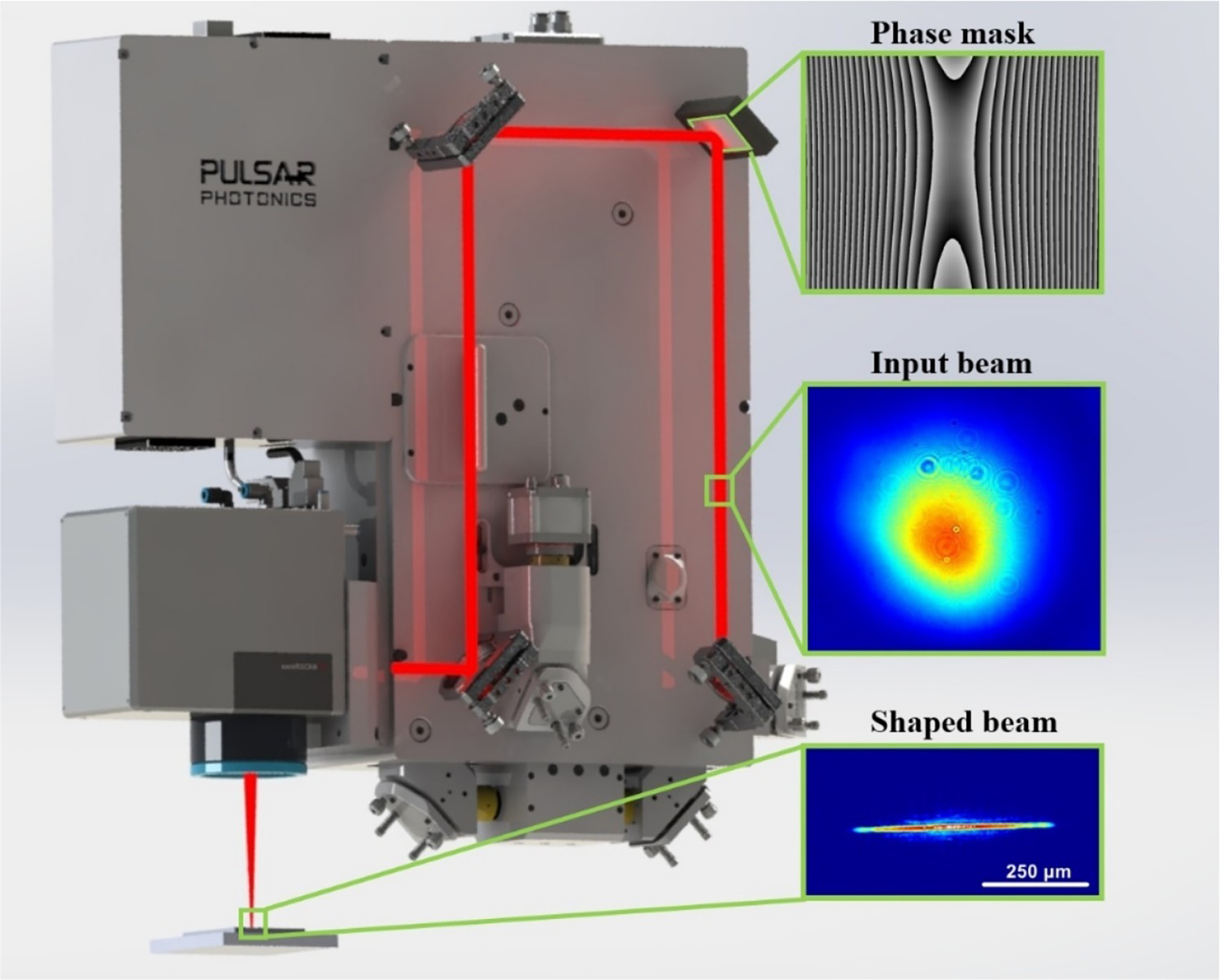
Sample analysis
Adhesion and coating thickness were measured by the ball-cratering method (CSM Calotest, bearing ball of 30 mm in diameter) and scratch test (CSM Revetest, testing load 0–100 N).
The beam shape was analysed by Basler ace acA3080-10µm camera with a pixel size of 1.67 µm. The surface morphology was investigated by laser scanning confocal microscope, Olympus OLS5000 and scanning electron microscope, Tescan MIRA, at electron energy of 15 keV.
The surface roughness of the laser-processed coatings was investigated using 3D optical profilometry (Zygo NV7200). Due to the unidirectional grooves made by laser texturing, the 3D surface roughness mapping method was used in order to average the roughness in-homogeneity obtained from the linear 2D tests carried out in several directions on the surface.
Friction test
Friction test parameters.

From the obtained data, the evolution of the friction coefficient (CoF) as a function of time and the number of cycles was analysed. Additionally, the ball wear rate and coating wear rates (both in units mm3 Nm−1) were calculated from the 3D images of the worn testing balls and worn coating surfaces using white-light optical profilometry (Zygo NV7200). This measurement was performed only for samples showing the best frictional properties.
Results and discussion
In the first set of experiments, optimal laser and processing parameters for the production of periodic nanostructures by different wavelengths were determined (see Table 2, Samples 1–3). Utilizing these parameters, different kinds of periodic nanostructures can be fabricated on the top of AlTiN coating completely rewriting the original coating microstructure, as depicted in Figure 2.
Overview of fabricated nanostructures. (a) reference sample coated by AlTiN; (b) LIPSS fabricated by 1030 Laser and processing parameters. Note: Samples 4–6 are fabricated by shaping the beam into 500 × 30 µm top-hat line.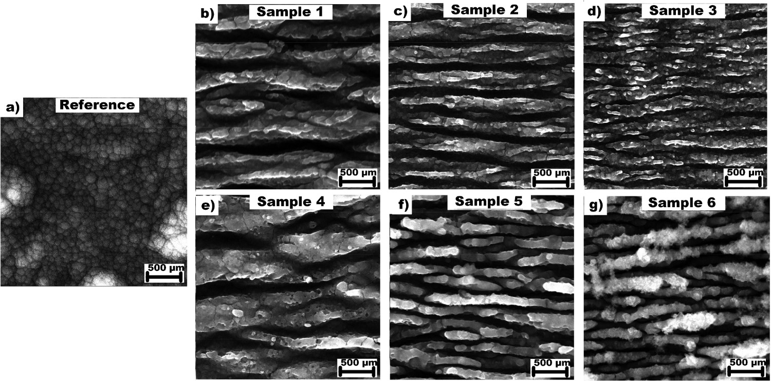
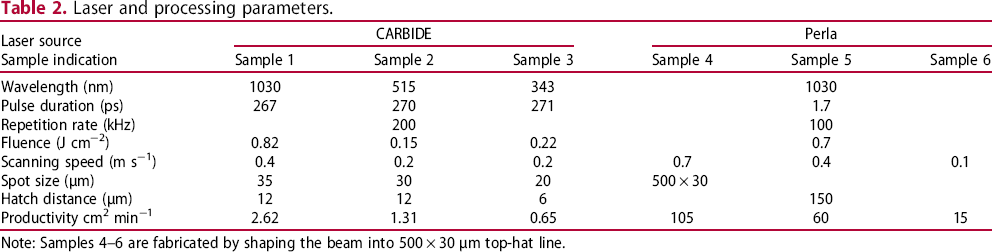
As can be observed in Figure 2(b–d), shorter wavelength leads to a change in structure periodicity. The longest period of 740 nm was observed for the structures fabricated by Carbide laser generating wavelength of 1030 nm (Sample 1). Utilizing second and third harmonics generation, periodicity decreased to 370 nm (Sample 2) and 273 nm (Sample 3) for the wavelength of 515 and 343 nm, respectively. As shown in Table 2, lower periodicity results in shorter hatch distance and thus lower productivity, which reached only 0.65 cm2 min−1 for the wavelength of 343 nm. Moreover, generation of shorter wavelengths is connected with a loss in average power – only 20 and 11 W are available for the wavelengths of 515 and 343 nm compared to 40 W at the fundamental wavelength of 1030 nm.
To address these issues, beamshaping technology was applied in combination with high energy pulsed laser system Perla. To increase the productivity and minimize the power loss, only the fundamental wavelength of 1030 nm was used with a shaped beam into the line with dimensions of 500 µm ×30 µm (see Figure 1). The shaped beam was then scanned over the sample in a direction perpendicular to the line axis. By optimizing the laser and processing parameters LIPSS structure similar to Sample 1 was fabricated on Sample 4 (see Figure 2(e)) with productivity reaching 105 cm2 min−1, 40 times faster compared to the single beam approach (2.62 cm2 min−1). In the next step, periodicity of produced LIPSS structures was tailored by different scanning speeds. By decreasing the original scanning speed of 0.7–0.4 and 0.1 m s−1 the periodicity decreased from 740 to 205 and 170 nm and productivity decreased to 60 and 15 cm2 min−1, respectively. As can be observed in Figure 2(f,g), the LIPSS are much shorter when slower scanning speeds are applied.
In the following step, surface roughness analysis was performed (see Figure 3). Generally, the surface roughness values are very sensitive to the heights and lateral dimensions of the LIPSS structures. Thus, to obtain presented Ra values the 3D analysis of the laser-textured coatings was performed to obtain average values for all lateral directions regardless of the directions of the laser grooves. As can be observed in Figure 3, the roughness of the laser-processed surfaces clearly corresponded to the size of the surface grooves observed in the SEM images (Figure 2). The drops and rises of the roughness values primarily depend on the surface grooves’ sizes (periodic imperfections) and long-distance surface asperities (random imperfections). The roughness analysis revealed that the smooth as-deposited coating surface exhibits the lowest roughness. Moreover, the low standard deviation demonstrates homogenous roughness values regardless of the scanning direction.
Typical surface roughness Ra
values of the as-deposited and laser-textured samples.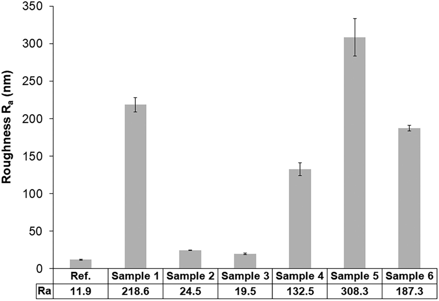
After heating the sample up to 500°C, the average roughness values did not change (not shown). Investigation of the surface by optical microscope showed a slight change of colour that is typically caused by the growth of a thin oxide layer on the top coating surface. However, a thin oxide layer generally has no effect on the friction and wear process.
After the laser processing, samples were subjected to tribological analysis at both room and elevated temperature of 500°C to simulate the application load and resulting heat production during manufacturing with functionalized tool. As can be observed in Figure 4, structures produced by different wavelengths have substantial effect on tribological behaviour during the friction run-in phase where we can observe significant improvement in the coefficient of friction (CoF) for laser-treated surfaces.
Typical CoF curves obtained at room temperature (a) for samples processed by different wavelengths (a) Samples 1–3 and for samples processed by productive beam-shaping technology in the IR region (b) Samples 4–6.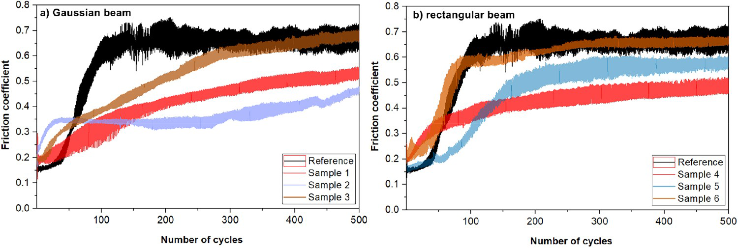
At room temperature, the LIPSS with the highest periodicity of 740 nm produced by the 1030 nm wavelength led to 21% improvement of the CoF after 500 cycles (Sample 1) compared to the reference value. For the shorter LIPSS period of 370 nm the CoF decreased by 32% (Sample 2) compared to the reference sample after 500 cycles. Interestingly, the shortest LIPSS period fabricated by UV wavelength (Sample 3) improved the CoF only in between 50 and 300 cycles. At 500 cycles, the CoF was the same as for the reference sample, implying that nanostructures were already worn out. The improvement of 27% (from 0.671 to 0.489) in friction coefficient after 500 cycles for Sample 4 is in accordance with a similar structure on Sample 1. However, decreasing the LIPSS periodicity by slower scanning speed did not improve the CoF. Structure on Sample 5, with the periodicity of 205 nm improved friction coefficient only by 14% and the smallest 170 nm period on Sample 6 had the same CoF after 500 cycles as the reference sample.
By heating the sample, situation changed dramatically. All laser-treated samples had higher CoF for the first 50 cycles and after 500 cycles only the robust LIPSS with a periodicity of 740 nm improved the CoF by 19% (from 0.677 to 0.551). Contrarily, LIPSS with shorter periods did not improve the CoF after 500 cycles (Figure 5).
Typical CoF curves obtained at 500°C (a) for samples processed by different wavelengths (a) Samples 1–3 and for samples processed by productive beam-shaping technology in the IR region (b) Samples 4–6.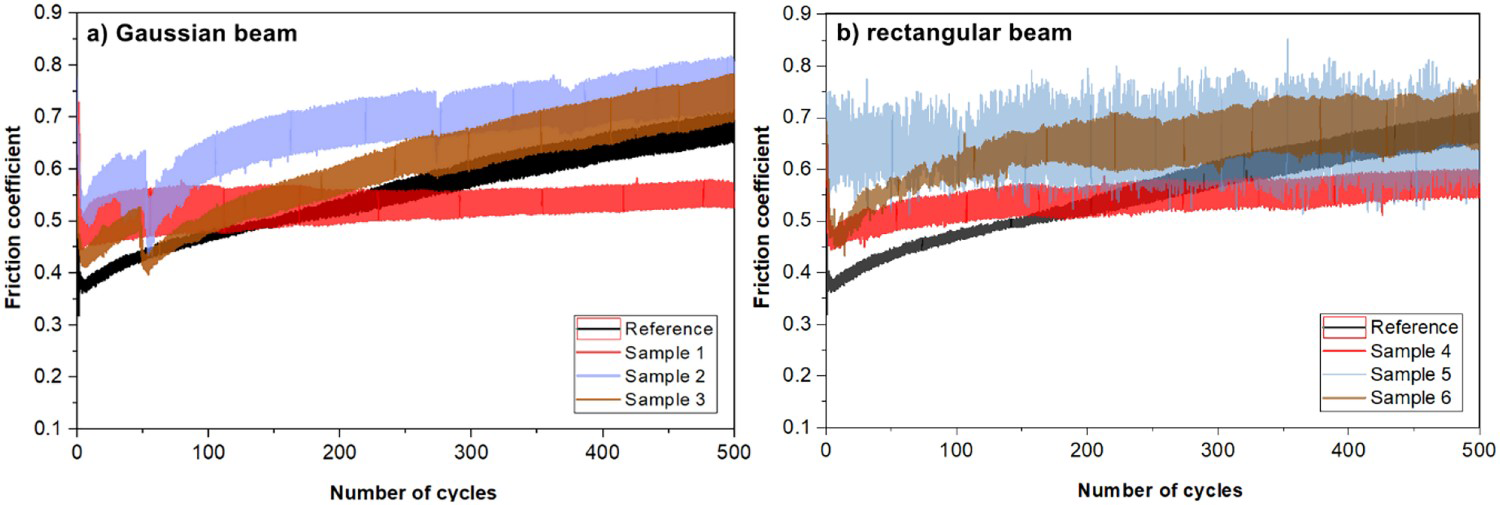
We can conclude that all tribological measurements at elevated temperatures were affected by specific changes in the coating structure that resulted in significantly distinct CoF evolution observed for the reference sample. At 500°C, the AlTiN surface is stabilized by surface oxides and the typical columnar coating structure on the top of the coating could change as well.
In all cases, LIPSS structures only affect the surface of the coating to about 50 nm in depth. Thus, start to be significantly worn out for higher number of cycles (above 500), and reaching a similar CoF as the reference after 1000 cycles, as demonstrated in Figure 6. Therefore, LIPSS had no significant effect on the CoF stabilization in the steady-state phase (500–1000 cycles).
Demonstration of the stabilization of the CoF evolution for 500–1000 cycles.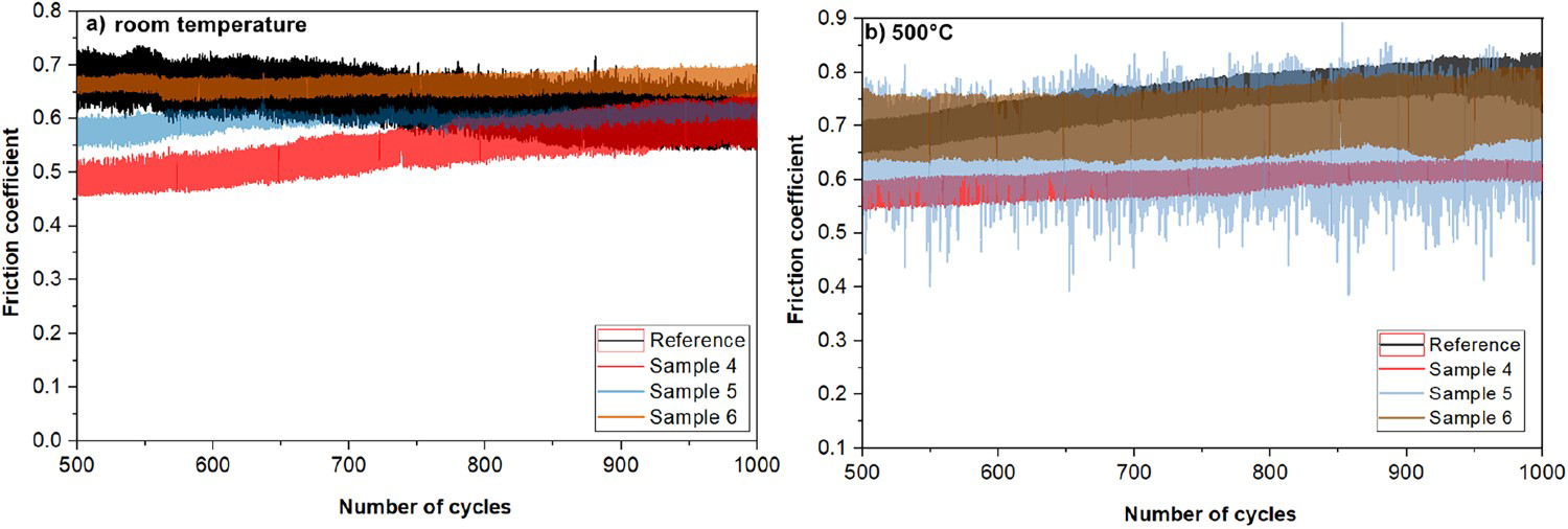
Thus, the most significant results are reached for the run-in phase where the wear rates of both interacting surfaces are typically the highest. It should be pointed out that for the most interacting surfaces, the run-in phase has a crucial effect on the steady-state tribology as well as on the durability and lifetime. The benefits of the laser-processed surfaces lay in the significantly lower CoF and much slower stabilization of the CoF value in the run-in phase that could, depending on the surface structure, result in lower wear of the interacting surfaces.
Based on the above results, the most robust structures with a periodicity of 740 nm on Sample 1 and Sample 4 exhibited the best overall performance regarding the friction reduction at both, room and elevated temperature to 500°C. Therefore, Sample 1 and Sample 4 structures were selected for the analysis of the wear rate of the testing ball and coating.
The wear rates of the testing ball were calculated from the mean dimension of the contacting area recorded by the 3D surface profilometry. The wear rates of the coating surface were determined from the multiple wear track 3D profilometry. The volume of the worn material was calculated from several wear track cross-section profiles subtracted from the unworn surface profiles. The total worn volume has to be normalized by load and total distance that the ball travelled in the wear track during the tribological test. As a result, the values of the wear rates in units of 10−6 mm3 Nm−1 are presented. Results obtained from the analyses of the reference sample as well as of Samples 1 and 4 at room temperature and at 500°C are shown in Figure 7.
The coating wear rates (a) and ball wear rates results (b) calculated from the surface 3D optical profilometry.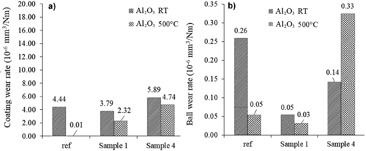
Generally, all obtained values of the coating wear rate were very low. The maximum wear depth in all cases did not exceed 300 nm. Hence the laser-made structures were already worn out, but the coating lifetime was not yet significantly affected. At room temperature, the wear rate of the reference sample was significantly higher compared to the hardly detectable wear track at 500°C. The wear rate values of the laser-processed coatings were well-comparable to the results of the reference sample. After the run-in phase, the textured surface was worn out and further friction and wear evolution could be similar because no significant in-depth change of the coating material caused by the laser-processing was expected. However, the coating wear rates were significantly higher at elevated temperatures. This could be caused by a much larger specific surface after laser processing and pronounced surface oxidation that could be responsible for higher production of hard wear debris present in the tribological contact. Second, due to the laser surface texturing that changed the initial surface roughness, the testing ball underwent a distinct wear evolution during the run-in phase that could have significant consequences for the coating wear evolution and the resulting value at the end of the test itself. These effects were observed in the ball wear scars (marked by arrows Figure 8) as well as in the coating wear tracks (Figure 9). The optical analysis of ceramic balls used for the friction test showed that the ball running against Sample 4 was worn by both the abrasion and the adhesion mechanisms at the same time, significantly increasing the ball wear rate (see Figure 7(b)). These results suggest that the LIPSS nanostructure on Sample 4 is more susceptible to abrasion compared to LIPSS nanostructure fabricated on Sample 1.
Optical analysis of ceramic balls after the tribological test at room and elevated temperature with marked ball wear scars. SEM analysis showing typical wear track of Sample 1 (a) and Sample 4 (b). The analysis of Sample 4 reveals shallow scratches (pronounced effect of abrasion).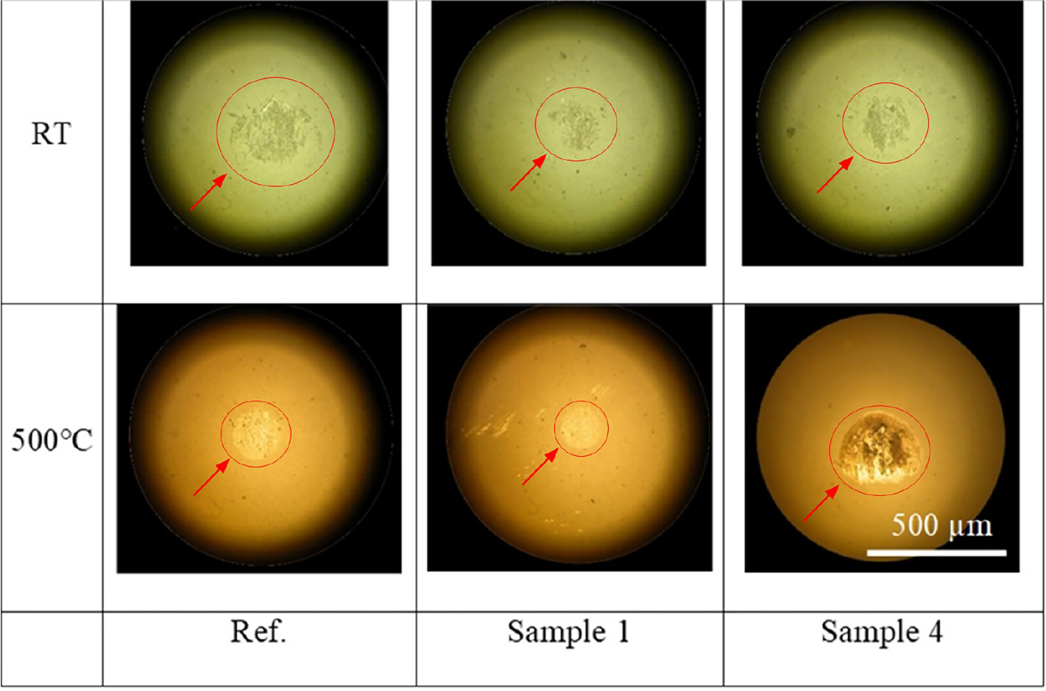
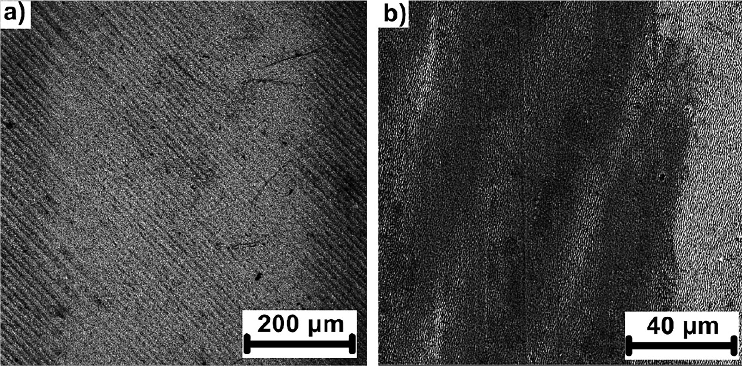
In the wear track on Sample 4, shallow scratches caused by hard particle ploughing due to abrasion were observed (Figure 9(b)). Additionally, the corresponding surface of the testing ball was more heavily covered by the third-body layer as a consequence of the adhesive wear. With regard to this observation, we concluded that the typical wear mechanism was a mixed abrasive/adhesive regime in this particular test. In the other tests (RT as well as at 500°C), the adhesive regime was present. However, the abrasive effect was suppressed (Figure 9(a)).
Conclusion
For the first time, a dynamic beamshaping technology has been utilized for a modification of friction properties on AlTiN-coated tool steel analysed at 500°C, simulating the workload conditions. The nanostructuring process developed at different wavelengths enabled LIPSS manufacturing with a periodicity between 273 and 740 nm. Consequent tribological analysis revealed that LIPSS with a periodicity of 740 nm exhibited the best overall performance in both, the wear and the friction improvement at room and elevated temperature demonstrating up to 27% improvement in CoF after 500 cycles at room and 19% at elevated temperature to 500°C compared to the reference. The manufacturing speed of LIPSS with 740 nm periodicity was significantly improved by 4008% by shaping the input Gaussian beam into the rectangular beam of 500 × 30 µm. The combination of these results shows that the proposed method can be scaled up for the mass production of functionalized machining tools which may enable dry machining. We believe that the results obtained within this study will help to develop efficient manufacturing processes without any costly and environmentally hazardous cutting fluids.
Footnotes
Disclosure statement
No potential conflict of interest was reported by the author(s).