
Abstract
The effect of tempering temperature on microstructure and mechanical properties of plasma welded martensitic heat-resistant steel P92 was investigated by tempering heat treatment process (tempering temperature range was 550–750°C, temperature interval was 100°C). The results show that with the increase of tempering temperature, the microstructure of welded joint coarsens, the tensile strength and hardness decrease, and the toughness is improved.In the tempering process, M23C6 and Laves phases are produced in the welded joint. A certain amount of M23C6 precipitates can strengthen the mechanical properties of the welded joint. Excessive M23C6 carbides lead to the softening of martensite and the decrease of hardness; the formation of Laves phase can inhibit the excessive precipitation of M23C6, but the excessive precipitation of the Laves phase will lead to coarsening at the grain boundary and the formation of voids at the grain boundary. When the welded joint temperature is 650°C, the comprehensive mechanical properties of the welded joint are the best.
Introduction
With the development of the power industry and the increasing global attention to the environment, the use of supercritical and ultra-supercritical units to improve the thermal efficiency of thermal power units has been put on the agenda. In order to solve the growing electricity demand of the fourth-generation power plants and alleviate greenhouse gas emissions, ASTM A213 T91 steel for seamless pipes, ASTM A335 P91 steel for seamless pipes and ASTM A387 Gr. 91 steel for steel plates have been developed [1]. Modified 9Cr–1Mo steel is a high-alloy ferritic heat-resistant steel and is now a potential candidate structural material for GEN-IV nuclear reactors [2].
In order to promote the development of higher grade materials, researchers from Belgium and Germany [3] added V to 9Cr–1Mo to obtain 9Cr–1Mo–V. By reducing the carbon content and adding trace elements to refine grains to improve high-temperature mechanical properties. The microstructure of the new material was tempered martensite.
To further obtain high performance heat-resistant materials, in the 1970s, 9CrlMoVNb(P91/T91) was developed by American Combustion Engineering Corporation and Oak Ridge National Laboratory on the basis of 9Cr1Mo steel, which had a small amount of V, Nb and other elements, and was developed with solid solution and dispersion strengthening theory [4]. T/P92 (9Cr–0.5Mo–1.8W–VNbN) is a ferrite steel with higher strength grade further developed on the basis of T/P91. It is based on T/P91 that W and a small amount of B are added to achieve strengthening. W plays a role in solid solution strengthening, and a small amount of B can improve the high-temperature strength of grain boundary. Ferritic steel (9%Cr, 1.75%W, 0.5%Mo) micro-alloyed with V and Nb and controlled the content of B and N elements has better high-temperature strength and creep properties than other ferrite alloy steels [5-7].
In terms of properties, G. Satyanarayana et al. [8] realised the maximum penetration depth and minimum welding width of P92 steel by identifying laser welding process parameters. Shanmugarajan B. P. Sathiya et al. [9,10] studied various properties of P92 steel by laser welding and determined the optimum parameters. Marko Dunzhuoer et al. [11], Michał Urzynicok, Krzysztof Kwieciński et al. [12] analysed the mechanical properties of P92 steel and the microstructure of heat affected zone (HAZ) after post-weld and post-weld heat treatment (PWHT) by MAG (135). It was found that the crack initiation energy increased due to the fine grain microstructure, but the crack propagation energy decreased. The properties of MAG welded joints were similar to those of TIG (Tungsten Inert Gas Welding) and SMAW (Shielded Metal Arc Welding) welded joints. Mohyla and K. Foldynová [13] tested the mechanical properties of welded joints of P92 steel by submerged arc welding. t was found that PWHT could significantly affect the mechanical properties of P92 welded joints formed by submerged arc welding. Sultan Alsagabi, [14] V. Skleničk, K. Kuchapurová [15], Aravinda Pai, Irappa Sogalad [16] studied the deformation behaviour, creep property, hardness, bending and tensile properties of P92 steel and modified 9Cr1Mo at high temperature. It was determined that the dominant high-temperature deformation mechanism was the high-temperature climbing of edge dislocation. Balamurugan Adhithan, Chandan Pandey [17] studied the effect of grain refinement of P92 steel base plate on mechanical and microstructure features of welded joints. The results showed that a homogeneous and refined grain structure was achieved for P92 steel after the double austenitising treatment compared to the conventional normalising treatment. Gaurav Dak, Sachin Sirohi et al. [18] researched on a dissimilar laser welded beam welded joint of quenched/tempered P92 steel, and 304L austenitic stainless steel has been examined in as-welded and PWHT at 760°C for 2 h for microstructural features and mechanical aspects. The results showed that the welded joint showed a decent combination of tensile strength and impact strength for both as-weld and PWHT conditions. The tensile results showed the failure of the 304L SS base metal, which ensured the acceptable strength of the weld metal for the laser-welded joints. The part of the welded joint with relatively poor impact strength was the weld metal.
At present, most of the research on P92 steel is the study of the weldability of the alloy itself. This paper will combine weldability and tempering performance, choose the best tempering temperature. In this paper, the welding joints of P92 steel were treated by tempering technology, and the influence of tempering temperature on the microstructure, second phase and mechanical properties of the welded joint was observed, and to explore the influence rule of tempering temperature on the mechanical properties of joints and reveal the specific reasons for its influence on the mechanical properties of joints.
Experimental method
Material
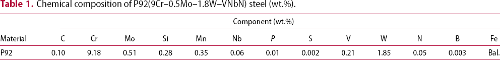
Chemical composition of P92(9Cr–0.5Mo–1.8W–VNbN) steel (wt.%).
Mechanical properties of P92(9Cr–0.5Mo–1.8W–VNbN) steel.

Mechanical properties and microstructure
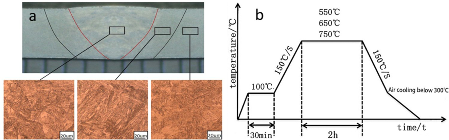
The butt welding of the 6 mm thick steel plate was carried out by plasma welding process. The schematic diagram of the welding process is shown in Figure 1(a), the locations of the microstructure, tensile, impact and hardness specimens are shown in Figure 1(b)–(e). When the welding current was I = 123 A, the plasma gas flow rate was Q = 4.6 L/min, and the welding speed was V = 170 mm/min, the formation of the weld surface was best, the macrograph of welded joint under welding state as shown in Figure 2(a). After getting a good welded joint, the heat treatment was carried out, the schematic diagram of the heat treatment process is shown in Figure 2(b). After heat treatment under different parameters, the tensile test (GB/T 228-2021) of the welded joint was carried out using the AGS-X300 KN universal testing machine produced by Shimadzu, Japan, and the yield strength of the welded joint under different heat treatment parameters was obtained. The WILSONVH1102 hardness tester (GB/T 231-2018) was used to obtain the hardness distribution of the welded joint under the as-welded condition (AW) and different heat treatment parameters. The JB-750W impact testing machine (GB/T 12778-2008) was used to test the distribution of the weld zone, HAZ and base metal zone of the welded joint under the optimal parameters. The impact toughness under the AW and different tempering temperatures was obtained. An Axio Scope A1 optical microscope, FEG-450 thermal field emission scanning electron microscope and EDS were used, combined with tensile fracture and impact fracture, the grain size change, precipitation phase, microstructure and mechanical properties of welded joints at different tempering temperatures were analysed.
Sample location and welding process (a) welding process (b) sample location diagram (c) tensile specimen (d) impact specimen (e) hardness specimen. (a) Macrograph of welded joint (b) diagram of heat treatment process.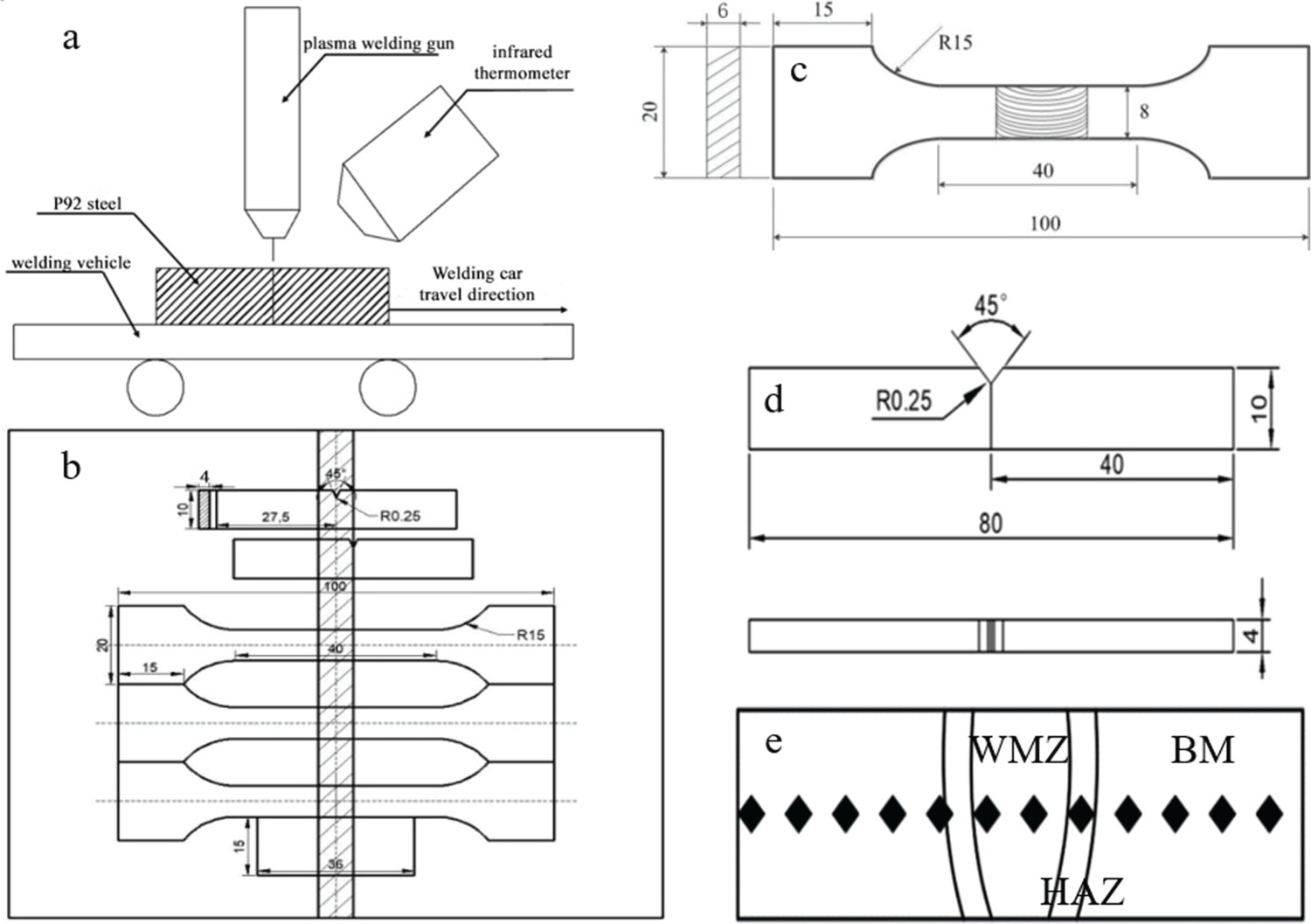
Results and discussion
Effect of tempering temperature on microstructure of welded joints
Macro photos of welded samples’ cross-section before and after different tempering are shown in Figure 3 and the microstructure of different regions of the welded joint under AW and tempering temperature of 550°C, 650°C and 750°C, respectively are shown in Figure 4. As shown in Figure 4(a)–(c), it can be found that the microstructure of the welded joint under AW was seriously coarsened and carbides appeared. After the final weld zone and HAZ were cooled at high welding temperature, dislocations are extended and adjacent lath martensite are merged, and then the density of dislocations is reduced, forming a martensite-based structure with retained austenite. Since the plasma arc has high heat in the welding process, the microstructure of the welded joint has been coarsened after the welding. Especially in the welding HAZ, it is found that the microstructure of the HAZ of the plasma-welded joint is seriously coarsened.
Macro photos of welded samples’ cross-section before and after tempering (a) AW (b) 550°C (c) 650°C (d) 750°C. Microstructure of welded joints at different tempering temperatures: (a) weld zone at AW, (b) HAZ at AW, (c) base metal at AW, (d) weld zone at 550°C, (e) HAZ at 550°C, (f) base metal at 550°C, (g) weld zone at 650°C, (h) HAZ at 650°C, (i) base metal at 650°C, (j) weld zone at 750°C, (k) HAZ at 750°C and (l) base metal at 750°C.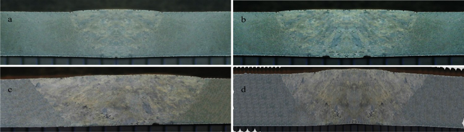
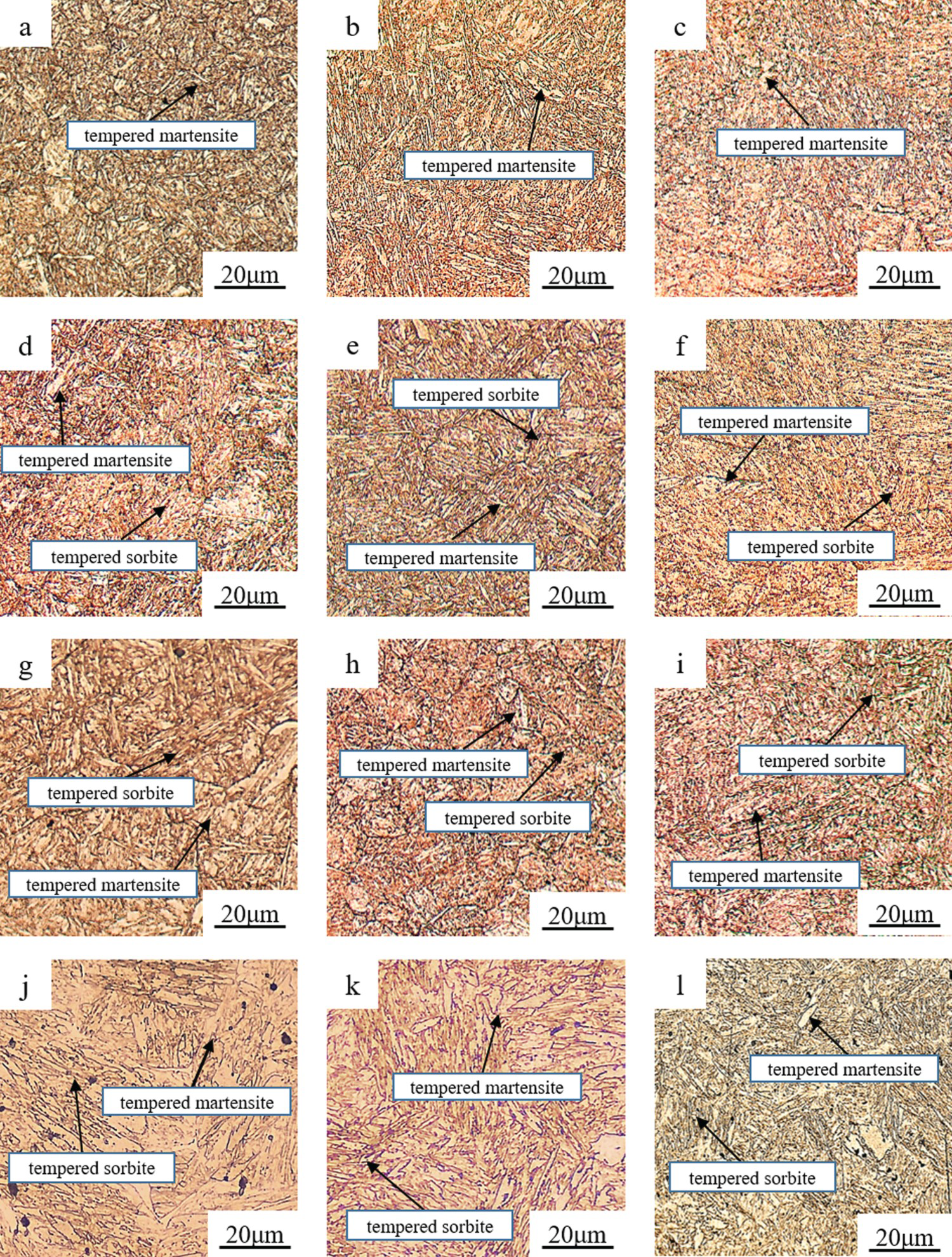
As shown in Figure 4(d)–(f), the welded joint was tempered at 550°C, and the microstructure of the weld zone of the welded joint was recrystallized. At a lower tempering temperature, a small amount of tempered sorbite appeared in each region of the welded joint. The tempered sorbite is a combination of ferrite and carbides that appeared in the tempering process of martensite structure, and it is mainly the product of high-temperature tempering. Therefore, the product of tempering at low temperature is mainly martensite matrix with sorbite distributed on it.
As shown in Figure 4(g)–(i), with the increase in tempering temperature, tempered sorbite continued to increase in the microstructure of the welded joint. At this time, a part of tempered sorbite appeared in each region of the welded joint, which increased the toughness of the welded joint. In the tempering process at 650°C, the appearance of tempered sorbite increased the comprehensive mechanical properties of welded joint. As shown in Figure 4(j)–(l), When the tempering temperature further increased to 750°C, the microstructure of each region of the welded joint occurred grain growth and coarsening, and there were more carbides occurred in welded joint. The appearance of carbides led to the decrease of comprehensive mechanical properties of welded joint because the corresponding tempering temperature was too high.
Precipitated phase at welded joints after tempering heat treatment
As shown in Figure 5, the precipitated phases of welded joints at different tempering temperatures were analysed. The 2-Theta range of XRD is 10–100°, the scanning mode is continuous scanning and the scanning speed is 2°/min. The main precipitated phase was obtained by XRD analysis, and then the precipitated phase was analysed by EDS. The XRD analysis of the precipitated phases after heat treatment of the welded joint showed that the main precipitated phases were M23C6 and Laves. As shown in Figure 6, EDS point analysis was carried out at the P92 plasma-welded joint, and SEM–EDS point analysis was carried out on the precipitated phase of the welded joint after heat treatment to obtain the composition of the intermediate phase precipitated at the grain boundary.
XRD diagram of welded joints at different tempering temperatures (a) AW (b) 550°C (c) 650°C (d) 750°C. SEM–EDS point analysis of the precipitated phase.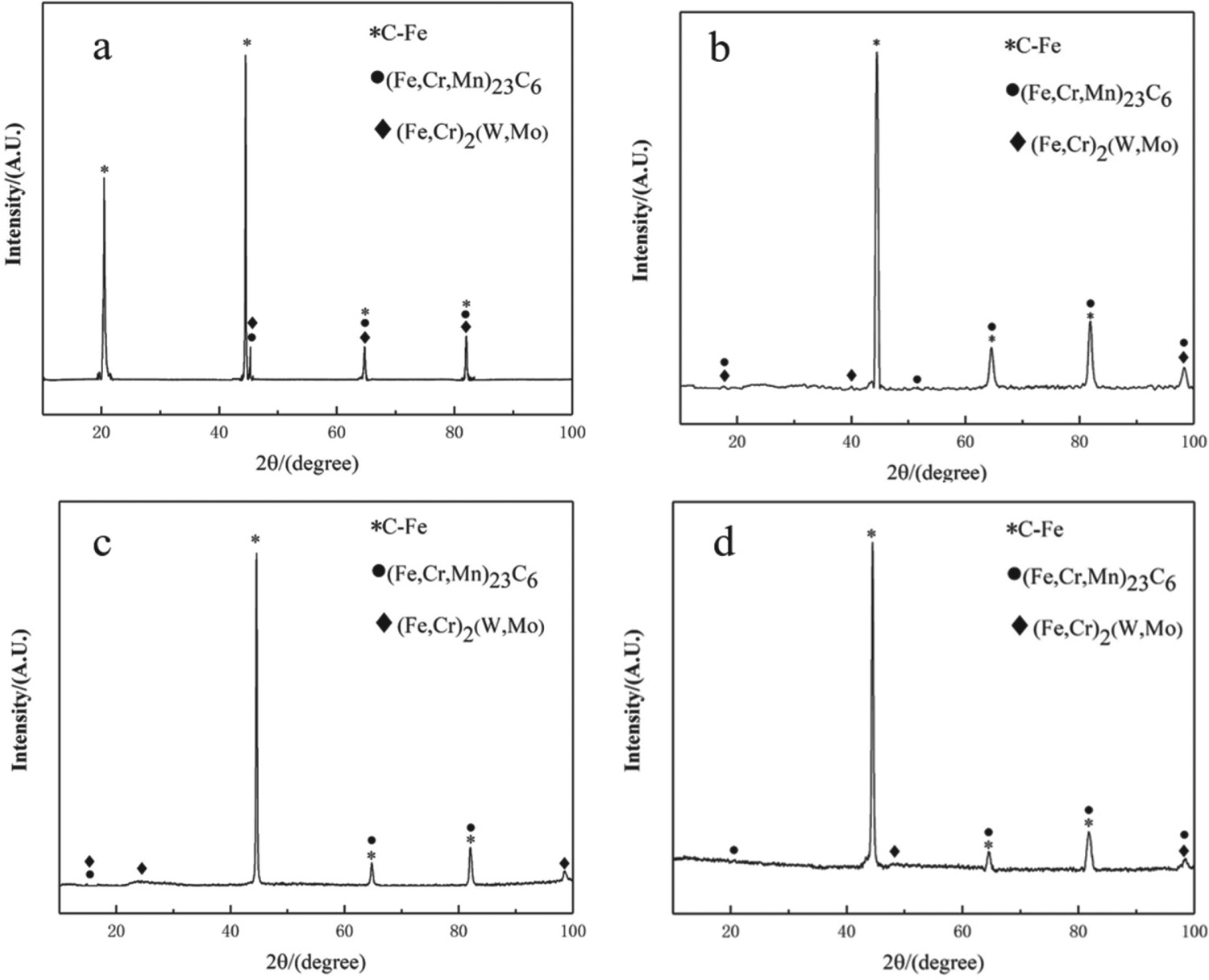
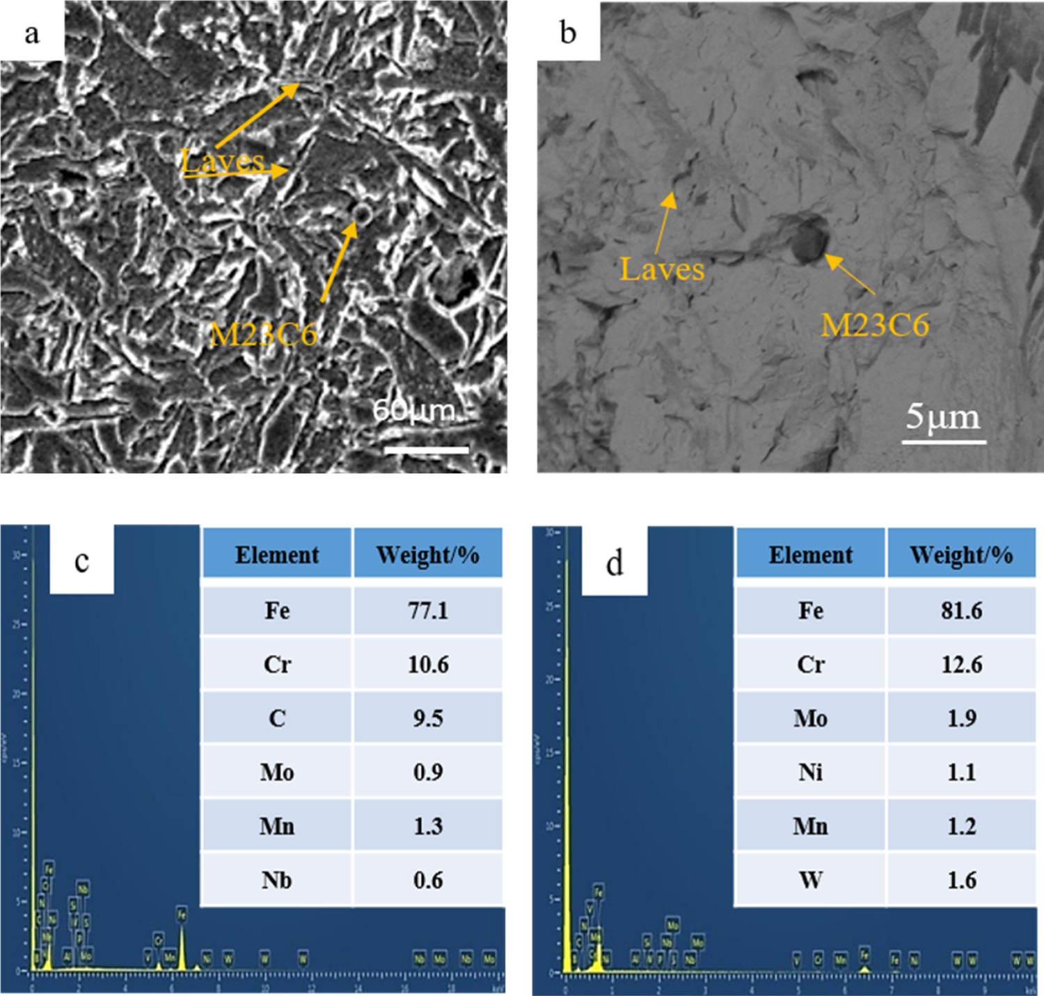
Figure 6(a) and 6(b) is the SEM of the EDS measurement position of the welded joint. As shown in Figure 6(c), the SEM–EDS point analysis of the precipitated phase M23C6 at the welded joint is shown. The carbide (Cr, Fe, Mo)23C6 composed of elements Cr, Fe, Mo and C will be continuously coarsening in the heat treatment process of the welded joint. Therefore, the heat treatment parameters should be strictly controlled in the heat treatment process. A certain amount of precipitated phase M23C6 will strengthen the mechanical properties of the welded joint. The SEM–EDS point analysis of Laves phase is shown in Figure 6(d). The phase was composed of a (Fe, Cr)2(W, Mo) compound with Cr, Fe and Mo. The formation temperature of the Laves phase was relatively high, which is formed at about 720°C. The formation of Laves phase can enhance the creep property of P92 plasma-welded joint, and its precipitation temperature was higher than that of carbide M23C6, so the precipitation of the Laves phase occurred later than that of carbide M23C6. Since the constituent elements of carbide M23C6 and intermediate phase Laves have common elements of Cr and Mo, the precipitation positions of carbide M23C6 and intermediate Laves were both formed at the grain boundaries of primary austenite and martensite.
Figure 7 is the EDS element distribution diagram of the welded joint. It can be seen from the figure that the welded joint is based on Fe, and Cr, Mo and W gather in a certain range. As a key element for the formation of carbides, C forms a carbon-poor region and a carbon-rich region within a certain range. M23C6 carbides will be preferentially formed in the carbon-rich region. Due to the low content of C in the carbon-poor region, the Laves phases with Cr, Fe, W and Mo as the main elements will be formed.
Distribution of main elements in welded joints.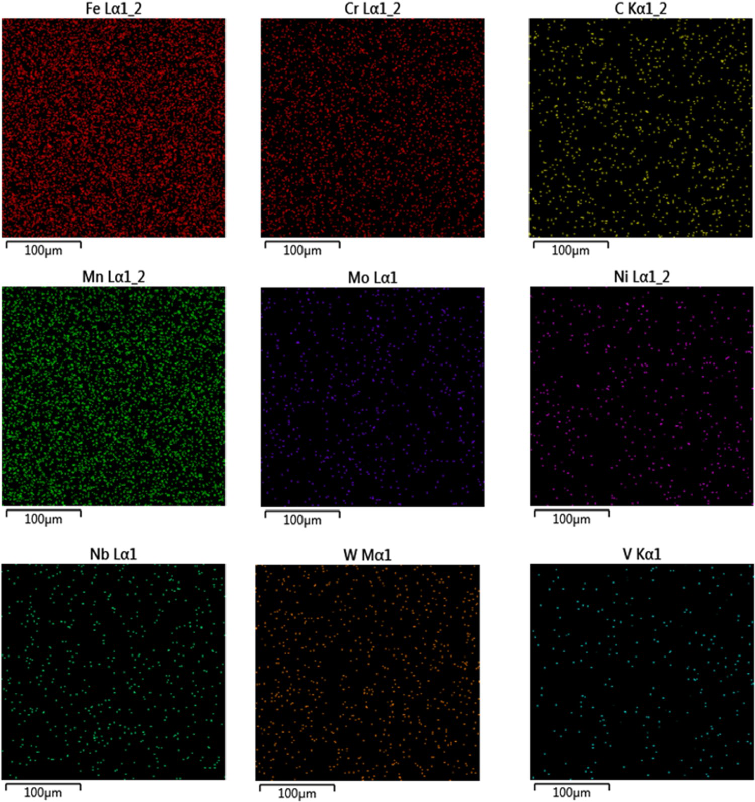
Effect of tempering temperature on the precipitated phase of welded joints
As shown in Figure 8(a)–(c), the microstructure of the base metal zone, HAZ and weld zone under AW were observed by SEM. It was found that a small amount of intermediate phase was formed in different zones of the welded joint under AW. Due to the arc temperature of plasma welding in the welding process can reach more than 2000°C, after welding, the welded joint is cooled rapidly, and the diffusion of alloy elements is limited to a certain extent. Therefore, the precipitated phase of the final welded joint was relatively small.
SEM microstructures of welded joints at different tempering temperatures: (a) weld zone at AW, (b) HAZ at AW, (c) base metal at AW, (d) weld zone at 550°C, (e) HAZ at 550°C, (f) base metal at 550°C, (g) weld zone at 650°C, (h) HAZ at 650°C, (i) base metal at 650°C, (j) weld zone at 750°C, (k) HAZ at 750°C and (l) base metal at 750°C.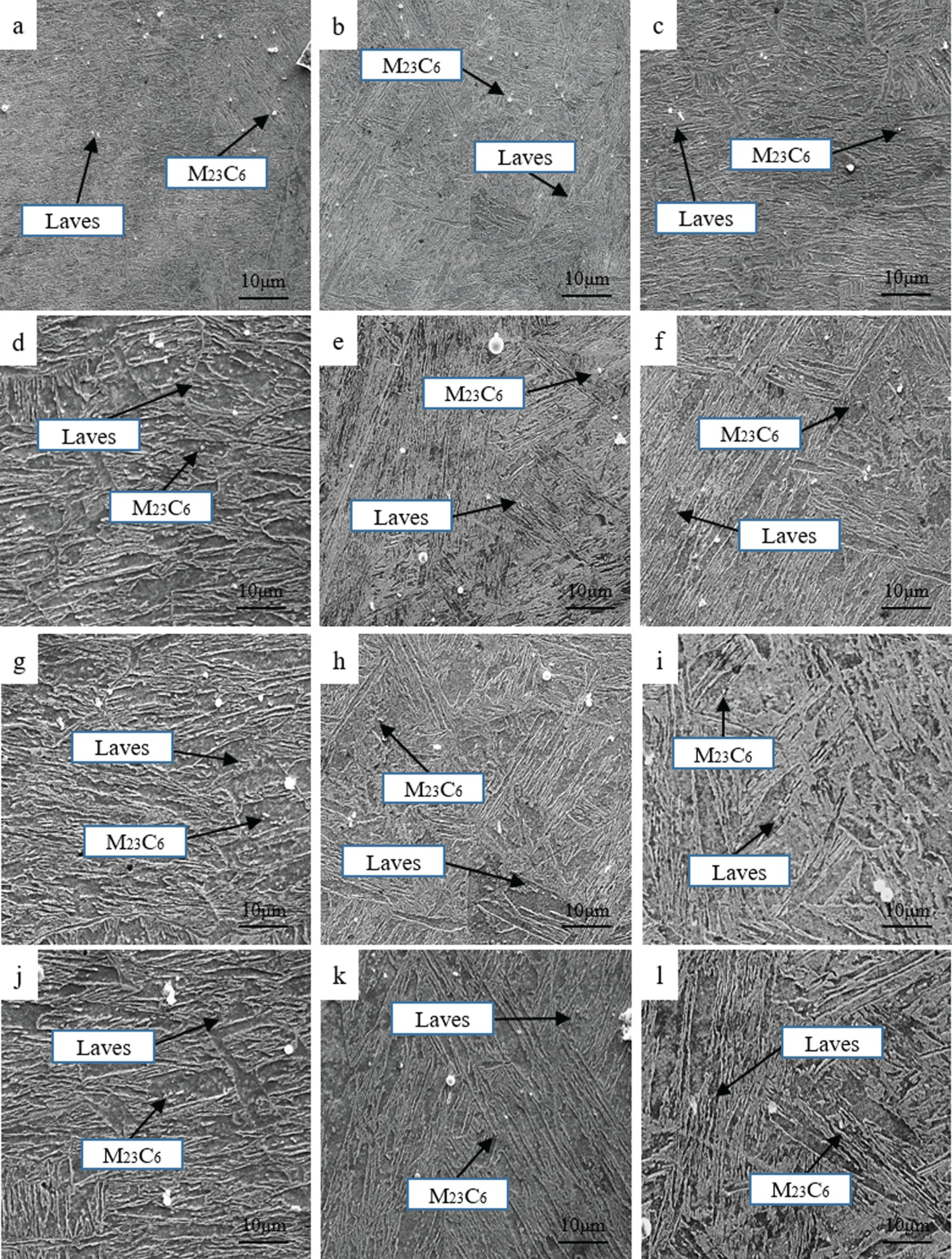
The SEM microstructures of the weld zone, HAZ and base metal zone of the welded joint after tempering at 550°C are shown in Figure 8(d)–(f). It was found that the precipitated phases appeared in all regions of the welded joint after tempering at 550°C, mainly including M23C6 and Laves phases. After tempering at 550°C, the content of precipitated phase M23C6 in the welded joint was much higher than that in the welded microstructure. After tempering at 550°C, the precipitation of a certain amount of intermediate phase M23C6 had a pinning effect on the migration of dislocations, which can effectively hindered the migration of dislocations and achieve the effect of precipitation strengthening. When the tempering temperature reaches 650°C, the SEM microstructures of the weld zone, HAZ and base metal zone of the welded joint are shown in Figure 8(g)–(i), the number and distribution of precipitated phase of the welded joint were improved compared to that under the previous tempering temperature.
The SEM microstructures of different regions of the plasma-welded joint of P92 steel at 750°C are shown in Figure 8(j)–(l). After tempering at 750°C for 2 h, the number and size of the precipitated phase in different regions of the welded joint were greater than those at 550°C and 650°C. At 750°C, the precipitated phases of the welded joint were too large, which not only failed to pin dislocations and increase precipitation strengthening but also led to coarsening of the microstructure and a reduction in the toughness of the welded joint.
After welding, there precipitated phases occurred in the welded joint. The precipitated phases were mainly M23C6 and Laves phases, which were mainly distributed at the grain boundary and subgrain boundary of the welded joint. An appropriate number of intermediate phases hinders the movement of the grain boundary and then pins the dislocations to affect solid solution strengthening. However, in the process of welding and PWHT, if too many precipitated phases M23C6 and Laves are produced, the C content in the matrix will be reduced, and the martensite structure will be softened. At the same time, the Cr content in the matrix will be reduced. Since Cr plays a role in promoting the creep strength of the matrix and the bonding strength between atoms, a decrease in Cr content in the matrix will reduce the bonding strength of the matrix and reduce the comprehensive mechanical properties of the welded joints.
Effect of tempering temperature on the mechanical properties of welded joints
Figure 9 shows the location of the fracture and the stress–strain curves of the welded joints at different tempering temperatures. It can be seen from Figure 9(a) that when the tempering temperature is 750°C, the tensile specimen breaks at the weld, and the remaining specimens break at the base metal. In Figure 9(b), it is found that the higher tempering temperature is, the lower the tensile strength of the welded joint. At the same time, the strain at the welded joint begins to increase, indicating that the toughness of the welded joint begins to improve. Therefore, when the tensile strength of the welded joint is guaranteed to a certain value, the tempering temperature should be set within a reasonable range. If the tempering temperature is too low, it cannot reach the effect of tempering heat treatment, and causes poor toughness. However, if the tempering temperature is too high, it will cause excessive precipitation of carbides at the welded joint, resulting in a decrease in the tensile strength of the welded joint.
(a) Tensile fracture diagram of welded joint (b) Stress–strain curves of welded joints at different tempering temperatures.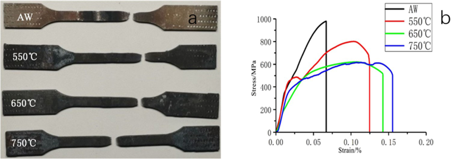
As shown in Figure 10, the tensile fracture of the P92 steel plasma-welded joint under different tempering temperatures and AW was obtained. In Figure 10(a), it is found that the tensile fracture of the P92 plasma-welded joint under AW presented a dissociated fracture mode. There were tearing ridges in the process of crack propagation. The appearance of tearing ridges hinders and delays the crack propagation. As shown in Figure 10(b) and 10(c), the tensile fracture of the final P92 plasma-welded joint at tempering temperature of 550°C and 650°C presented a dissociative fracture. After the tempering of the P92 plasma-welded joint, it is found that there were smaller dimples in the tensile fracture. In addition to dimples, there are more massive structures and holes in the tensile fracture. The reason for these phenomena was that the emergence of carbides hindered the crack propagation process. As shown in Figure 10(d), due to the high tempering temperature, the final tensile fracture of the P92 plasma-welded joint at the 750°C tempering temperature showed a dissociative fracture mode, and the microstructure grew and coarsened, which reduced the toughness of the welded joint. The tensile fracture presented more holes and massive structures, and the mechanical properties of the welded joint were poor in this mode.
Tensile fracture of welded joints at different tempering temperatures: (a) AW, (b) T = 550°C, (c) T = 650°C and (d) T = 750°C.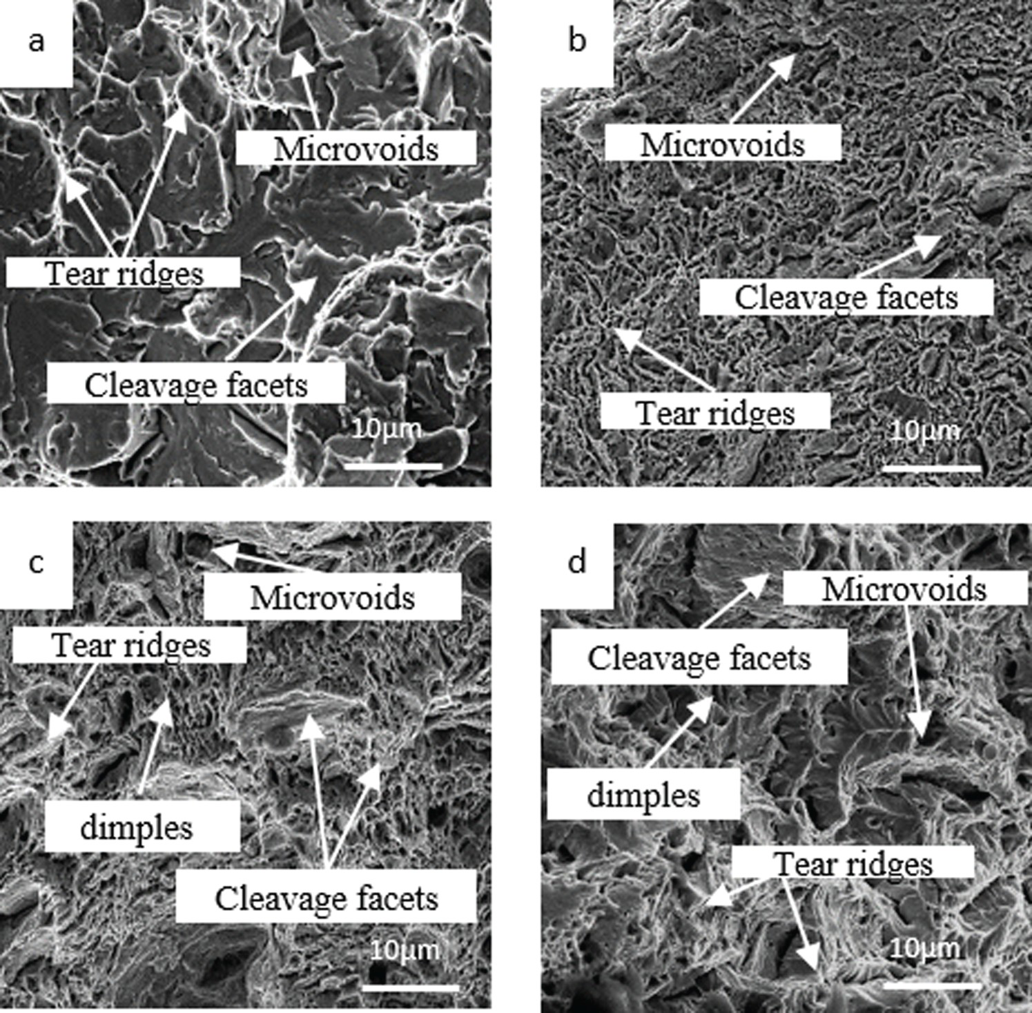
Effect of tempering temperature on the impact properties of welded joints
The hardness distribution of the welded joint at the AW and at different tempering temperatures is shown in Figure 11. It is found that with the increase in tempering temperature, the hardness of the weld zone at the welded joint changes most obviously. With the increase of tempering temperature, the hardness decreases in turn. When the tempering temperature was 650°C, the hardness value was approximately 250 HB. If the tempering temperature continued to increase, the original martensite structure transformed into tempered troostite in different regions of the welded joint. Since the martensite structure was a hard and brittle phase, martensite will decomposed during tempering, and finally, the hardness was too low.
Hardness distribution of welded joints at different tempering temperatures.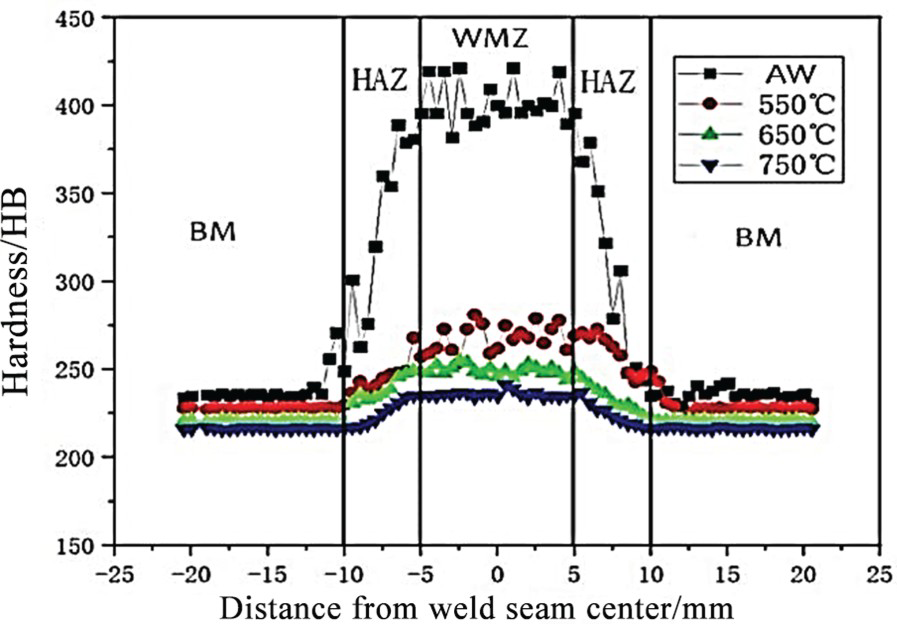
Effect of tempering temperature on the impact properties of welded joints
As shown in Figure 12, the impact macroscopic fractures of the base metal zone (BM), HAZ and weld zone (WMZ) at different tempering temperatures are shown. It can be seen from the figure that shear lips existed in the fracture of the base metal in the four states. With the increase in temperature, the macroscopic fractures of the BM did not change much. Obvious shear lips can be seen in the HAZ and WMZ at 650°C and 750°C. This indicates that the toughness of the material was improved after heat treatment.
Impact macroscopic specimens of welded joints at different tempering temperatures.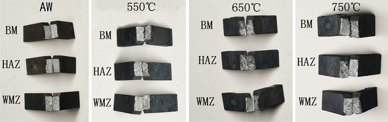
Figure 13 are the load–displacement curves of different regions of the welded joint under different tempering temperatures, and Figure 13(a) is the load–displacement curves of the WMZ at different tempering temperatures. It can be seen from the figure that under the AW condition, the impact curve of the WMZ had almost no yield stage, and the sample reached the maximum force after the elastic deformation stage. Then the unstable crack propagation occurred, and the initial displacement of the unstable crack was relatively small, indicating that the toughness of the material was poor under AW conditions. After heat treatment of the sample, it can be seen that the curve had a clear yield stage after tempering at 550°C, then after reaching the maximum force, cracks appeared and there was a certain stable crack propagation. The initial displacement of the unstable crack was still small but the toughness was improved compared with that under the AW condition. As the temperature increased to 650°C, the material had obvious stable crack propagation and toughness greatly improved. Compared with that at 650°C, the impact load of the material at 750°C was reduced, but the toughness was still improved. It can be seen from the curve that after the stable crack propagation, the material had almost no unstable crack propagation. Cracks propagated stably until fracture, reflecting typical ductile material properties.
Load–displacement curves and diagram of notch position at different tempering temperatures (a) WMZ (b) HAZ.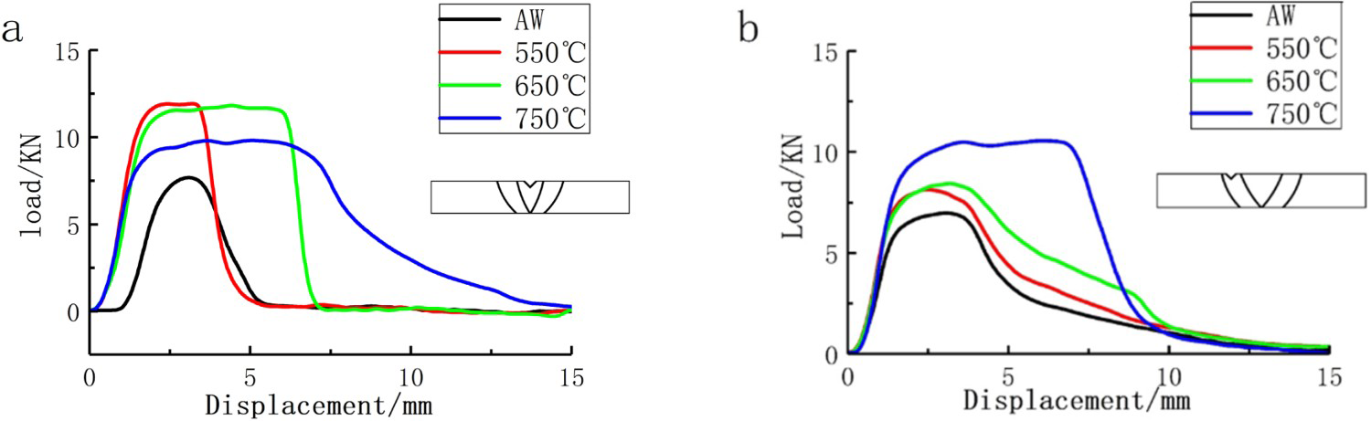
Impact energy of welded joints at different tempering temperatures.
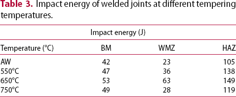
Figure 13(b) is the load–displacement curves of the HAZ at different tempering temperatures. It can be found from the curve that the curve trend of the HAZ was basically the same under different heat treatment conditions, and the difference was that the impact absorbed energy was different. The load–displacement curve of the HAZ under the AW had no stable crack propagation stage. When the maximum force was reached, a crack was generated, and unstable crack propagation occurred. Although there was a certain stable crack propagation, the toughness is generally poor and has the characteristics of brittle materials. The material tempered at 550°C had cracks after reaching the maximum force. At this time, the cracks propagated stably. After the unstable propagation of the cracks, the stable propagation of the cracks appeared again but the toughness was relatively unable to meet the requirements. After tempering at 650°C, it can be found from the curve that the difference between the initial displacement and the final displacement of the unstable crack propagation was small, and then there was a stable crack propagation, which indicated fairly good toughness. When the tempering temperature reached 750°C, the HAZ had an obvious stable crack propagation stage after reaching the maximum force, and the initial displacement of unstable crack propagation was large, which is characteristic of ductile materials.
Figure 14 shows the impact fracture morphology of the welded joints in different regions at different tempering temperatures. Since the final impact energy of the BM was basically the same, the impact fracture of the BM under different tempering heat treatment parameters was no longer analysed individually. It can be seen from Figure 14, the morphology of the impact fracture gradually converted from brittle fracture into ductile mixed fracture. The microstructure of the WMZ and HAZ in the AW was coarsened after thermal cycling [19]. As shown in Figure 14(a), the fracture of the WMZ presented a cleavage fracture mode, and the cleavage platform of the river pattern was clearly observed, reflecting brittle characteristics. In these low-toughness specimens, the fracture propagation originated from the notch and passed through the WMZ, HAZ and BM [20], The schematic diagram of the notch position is shown in Figure 13(a) and 13(b). Other researchers also made similar observations, such as Mortia et al. and Zhang et al. [21,22] who studied the effect of notch position on the impact toughness of WMZs and HAZs. The poor impact of WMZ Charpy under AW was mainly due to the formation of brittle martensite of C and the formation of soft ferrite patches with the increase of W and Mo contents [1,19,23]. As shown in Figure 14(b), the fracture of the HAZ also shows brittle characteristics. Different from the WMZ, the tearing ridges were observed, but the overall toughness was still fairly poor. The impact fracture of the BM under the AW was shown in Figure 14(c). The existence of dimples and tearing ridges can be observed from the figure. Because of the lower influence of the thermal cycle, the toughness of the BM was better under the AW condition.
Impact fracture of welded joints at different tempering temperatures: (a) WMZ at AW, (b) HAZ at AW, (c) BM at AW, (d) WMZ at 550°C, (e) HAZ at 550°C, (f) WMZ at 650°C, (g) HAZ at 650°C, (h) WMZ at 750°C and (i) HAZ at 750°C.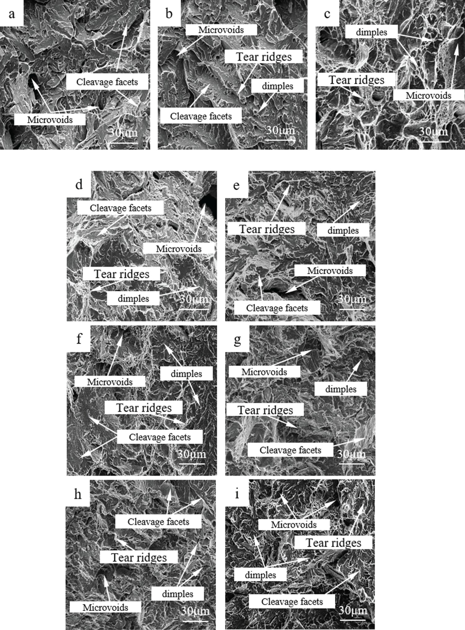
As shown in Figure 14(d) and 14(e), after tempering at 550°C, the plastic deformation of the WMZ and HAZ increased, and small dimples and tearing ridges appeared in the fracture. Transition of materials from brittle fracture to quasi-cleavage fracture. After tempering at 650°C, the number of dimples and tearing ridges in the WMZ and HAZ increased. It can be seen from Figure 14(f) and 14(g) that most of the dimples were flat. The increasing number of dimples indicated that the toughness of the material was greatly improved. Figure 14(h) and 14(i) show the fracture morphology after tempering at 750°C. The plastic deformation of the WMZ and HAZ fracture increased obviously, which is a typical mixed morphology of dimple and cleavage fracture. There were river-like patterns on the edge of the dimple due to slippage. With the increase of tempering temperature, the toughness increased. Due to the tempering effect, the impact toughness value of PWHT increased and this kind of failure mode had ductility [24]. With the increase in temperature, the toughness of the material increases but its strength will decrease. Heat treatment led to the precipitation of new carbides resulting in the softening of martensite [25,26]. Based on various results, the heat treatment temperature was selected from 730°C to 760°C [20,27,28]. Combined with this experiment, it was determined that the best tempering temperature was 650°C.
Conclusions
In this study, the P92 steel plasma-welded joints were tempered to investigate the mechanical properties of the P92 steel plasma-welded joints at different tempering temperatures. The precipitated phases in the welded joints at different tempering temperatures were analysed by XRD and SEM–EDS. Based on the different experimental measurement results, the following conclusions can be drawn.
With the increase of tempering temperature, the grain structure of the welded joint gradually grows up, and the tensile strength of the welded joint decreases, but at the same time, its toughness improved. Finally, it is concluded that the comprehensive mechanical properties of the welded joint are the best when the tempering temperature is 650°C. Carbides (Cr, Fe, Mo)23C6 are generated at the welded joint during tempering. A certain amount of precipitated phase M23C6 will in determining the mechanical properties of the welded joint. However, with the increase in tempering temperature, excessive carbides of M23C6 will reduce the mechanical properties of the welded joint. The segregation of Cr and Mo elements in the matrix causes a large number of Cr-poor elements in the matrix, and the C content of the matrix element will decreases, which leads to the softening of the martensite structure and a decrease in the hardness, resulting in the transformation of the matrix structure from the martensite phase to ferrite. The (Fe, Cr)2(Mo, W) Laves phase is produced at the welded joint during tempering. The precipitation of the Laves phase occurs later than that of carbide M23C6, and the formation of the Laves phase inhibits the precipitation of M23C6. Therefore, a certain amount of the Laves phase can prevent the excessive precipitation of carbide M23C6 so that preventing the softening of martensite.
Footnotes
Disclosure statement
No potential conflict of interest was reported by the author(s).