
Abstract
Endoscope localization is important as it provides location information for disease diagnosis and treatment. Here, we describe a simple and highly accurate electromagnetic method for endoscope localization. The system includes an emitter circuit, a receiver circuit, and a signal acquisition and processing circuit. A new receiver apparatus was designed to improve the sensitivity and accuracy of localization. A virtual colon imaging method is also presented.
Introduction
During diagnosis and operation with endoscopes, it is highly desirable to be able to visualize the location of the endoscope and the abnormal tissues inside the body. Various endoscope localization and dynamic tracing methods have been developed. X-ray method is expensive and has the concern of excessive radiations to the body. Ultrasound method needs water medium, potentially complicating the operation. Considering the accuracy, the cost, the speed, and the operation complexity, method of electromagnetic localization is well selected as the first choice. This method uses a set of receiver coils to detect the electromagnetic signal induced by the electromagnetic field generated by the emitter coils. 1 –4
Many algorithms for electromagnetic localization method have been developed based on the specific spatial feature of the electromagnetic signal caused by driving electrical coils sinusoidally. Several instruments of endoscope localization have developed, such as one developed by Olympus, which has been used for clinical applications. 5,6 The limitations of the existing systems include insufficient accuracy, excessive complex, and lack of user-friendliness as the display result does not suit to doctor's operation habit.
The accuracy of localization is determined by the distance between the emitter and the receiver. Larger distance usually results in a relatively weak receiver signal. As the intensity of the receiver signal is inversely proportional to the third power of the distance, the emitter should be as close to the receiver as possible. Here, we propose a method of fixing the receiver in the human body, which improves accuracy because of a shorter distance between the emitter and the receiver. The method allows well display of the whole image of the endoscope when the patient lies on his/her side, for the human body act as the reference frame itself in all postures. We also propose a method of concurrently showing a virtue colon image in addition to the endoscope image, making it easy to define the position of the distal end of the endoscope in colon.
Principle and Method
Structure of the Whole Localization System
Structure of the whole localization system is showed in the Figure 1. The process of locating the endoscope can be described as below. First, the control unit controls emitter drive electronics to generate an exciting sine signal to drive emitter in the endoscope, which therefore generate electromagnetic wave in space. Nine coils of three receivers with given positions produce electrical signals with certain amplitude and phase in response to the sine electromagnetic wave. Under the control of control unit, all together or in sequence, these signals are amplified and filtered in measurement unit and dealt with analogue to digital convertion and fast fourier transformation (FFT) process in data process unit. The data with useful information will be used in certain algorithm for localization in control unit, and the position of emitter will be calculated. Then, the curve of endoscope, which represents the position of every emitter in the endoscope, can be obtained by fitting a curve to certain points. Finally, the fitted curve will be displayed in display unit.
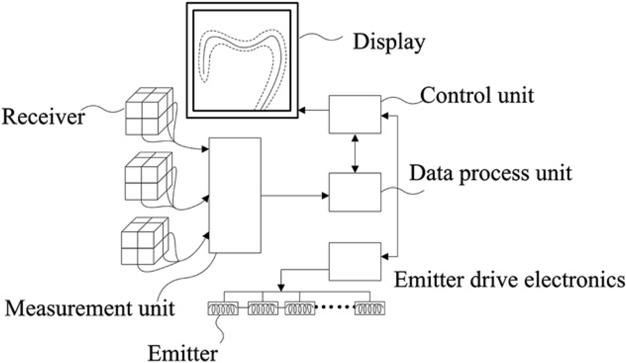
Structure of the whole localization system.
Here, the receiver and the emitter have similar function in the process of localization, so they can be exchanged in functions. It is feasible to use the emitter outside and the receiver inside the endoscope.
Localization Algorithm
The fundamental principle of electromagnetic method for localization is that electromagnetic signal caused by driving electrical coils with sine signals has a specific spatial feature. In this article, a fast and simple iterative algorithm is used to conduct the calculation, 7 and will be described below.
As shown in Figure 2, the receiver with three axes of coils that are pointed to x-axis, y-axis, and z-axis, respectively, is located at origin, emitter P is a coil with axis pointed to vector S, R is the distance between the receiver and the emitter. As the voltage induced in the receiver is only related with the position and the orientation of the emitter, then formulas with induced voltage and position of the emitter x, y, z, inclination angle θ and rotation angle Φ can be conformed.
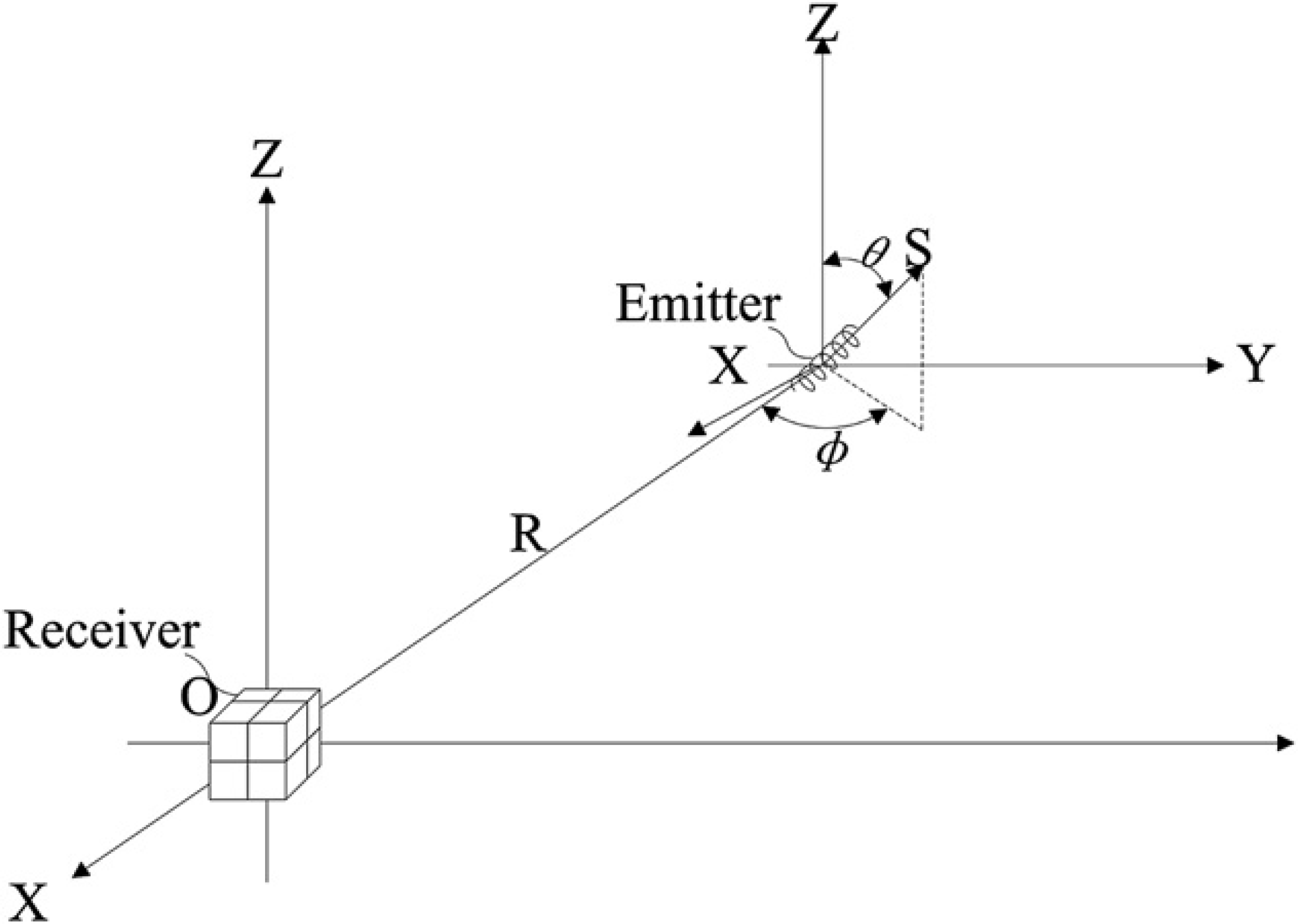
Parameters for determining position.
As shown in Figure 3, d is the distance between the receiver and the emitter, α is the angle between the emitter coil's axis and the line between the emitter and the receiver, and ψ is the angle between the receiver coil's axis and the line between the emitter and the receiver when emitter produces sine electromagnetic wave, the intensity of field at the receiver point can be expressed in formulas (1) and (2) (k c is a constant related to the number of turns of coils, area of coils, and electric current magnitude):


Then, with formulas (1) and (2), formula below can be deduced as:

As it is shown in Figure 4, O is the receiver with three axes of coils; the three coils produce voltage signals V s 0x , V s 0y , and V s 0z in response to the sine electromagnetic wave produced by the emitter. Then with formulas (1) and (2), it can be also deduced to formula (4) (k cks is a constant related with number of turns of coils, area of coils, and electric current magnitude):

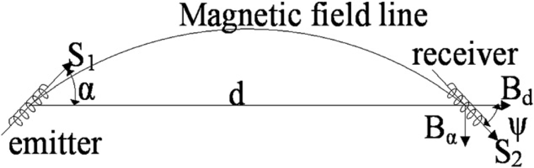
Emitter generates magnetic field line.
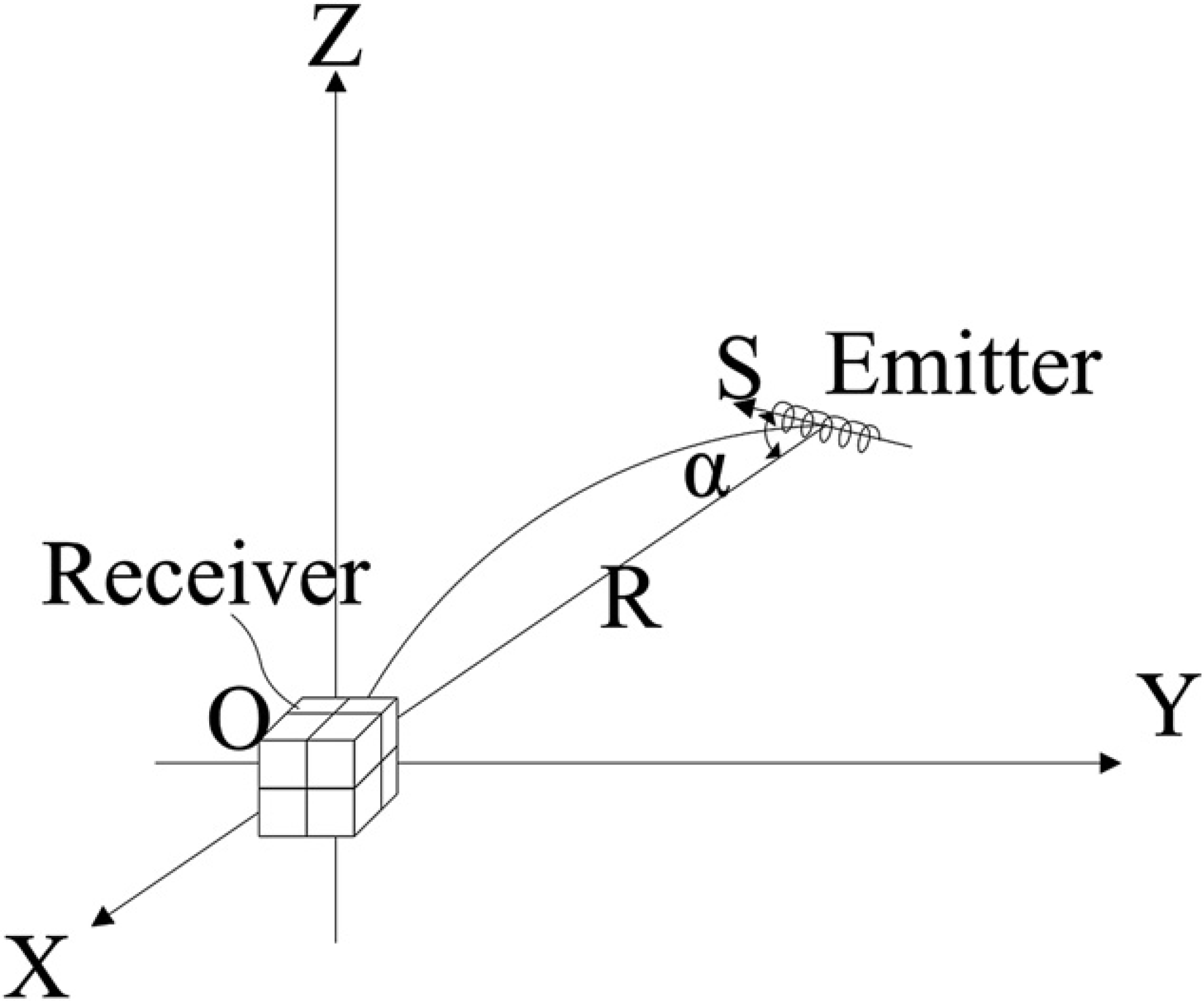
Receiver with three axes of coils produces voltage.
Based on the principle of the fast and simple iterative algorithm introduced above, the position and the orientation of the emitter can be obtained easily.
FFT Process in Data Process Unit
As method of generating several sine signals in different frequencies at the same time is used in the system, it is necessary to take FFT process to get signals information in every frequency. To reduce the error caused by spectrum leakage in FFT process, a matrix for adjustment besides taking Blackman-Harris window is made. 8
Simulation in Labview proved that it can achieve almost zero error with limited number of samples and frequencies of signals Fn which is not equal to n* Fs/N (n = 0, 1, 2…N − 1) (Fs is sampling rate, N is number of samples), when all sine signals have a same phase.
A New Receiver Apparatus
The intensity of the received signal, which is inversely proportional to the third power of the distance, will decrease sharply when the distance between the emitter and the receiver becomes large. An excessively large distance will cause difficulties in acquiring effective signal with useful information, which makes the accuracy of localization reduce and limits the localization space. A method of fixing the receiver on human body shown in Figure 5 is proposed, by which the localization accuracy can be improved.
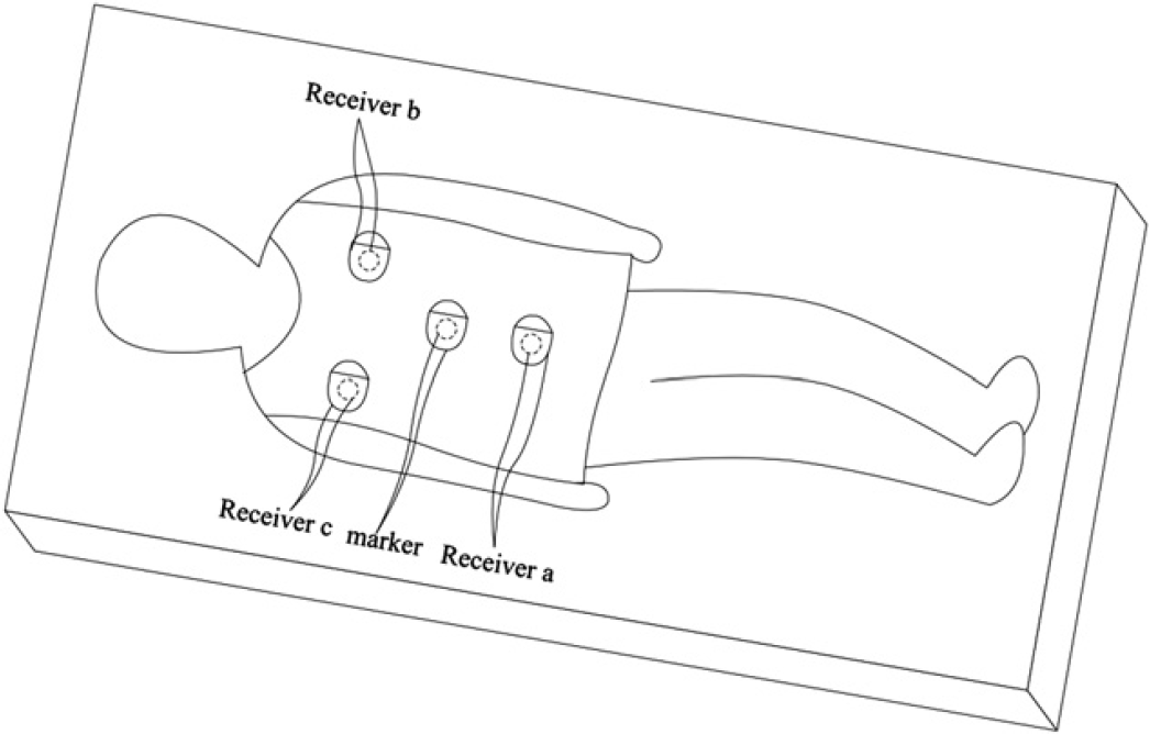
Method of positioning the receivers and marker.
As shown in Figure 5, a jacket that can be dressed and fixed well around the human body is designed. A surface plate can be fixed on anterior body by fixing it in the jacket. Receiver a, Receiver b, Receiver c, and a marker are fixed in the surface plat. Receiver a, Receiver b, and Receiver c are arranged evenly around the colon, for example, they can be at the vertex of a regular triangle, and the marker can be fixed at the belly button.
In current endoscope localization system (such as Olympus product), the marker fixed on human body and the receivers placed beyond human body are separate. The method we proposed for fixing receivers and marker can reduce complexity of the system and cut down the cost. The intensity of the received signal can be improved, because the distance between the emitter and the receiver is shorter in this way. A higher accuracy under the same level of signal driving and processing can be achieved.
Besides, the display result will more suit to doctor's operation habit, because the human body is the reference frame itself. When the patient turns his body, the image of the fitted curve of the endoscope will not turn at all. In this way, the whole image of the endoscope can be displayed all the time during the operation without having some parts of the curve sheltered by other parts.
Add a Virtual Colon Image to Display
To make it easier to define the position of the distal end of the endoscope in colon, method of showing a virtual colon image besides the endoscope image on the screen at the same time is proposed. As shown in Figure 6, Figure 6-1 shows the image of the fitted curve of the endoscope with the virtual colon image when the endoscope is inserted into the colon totally. Figure 6-2 shows the image of the fitted curve of the endoscope with the virtual colon image already acquired in the progress of insertion when part of the endoscope has been drew out.
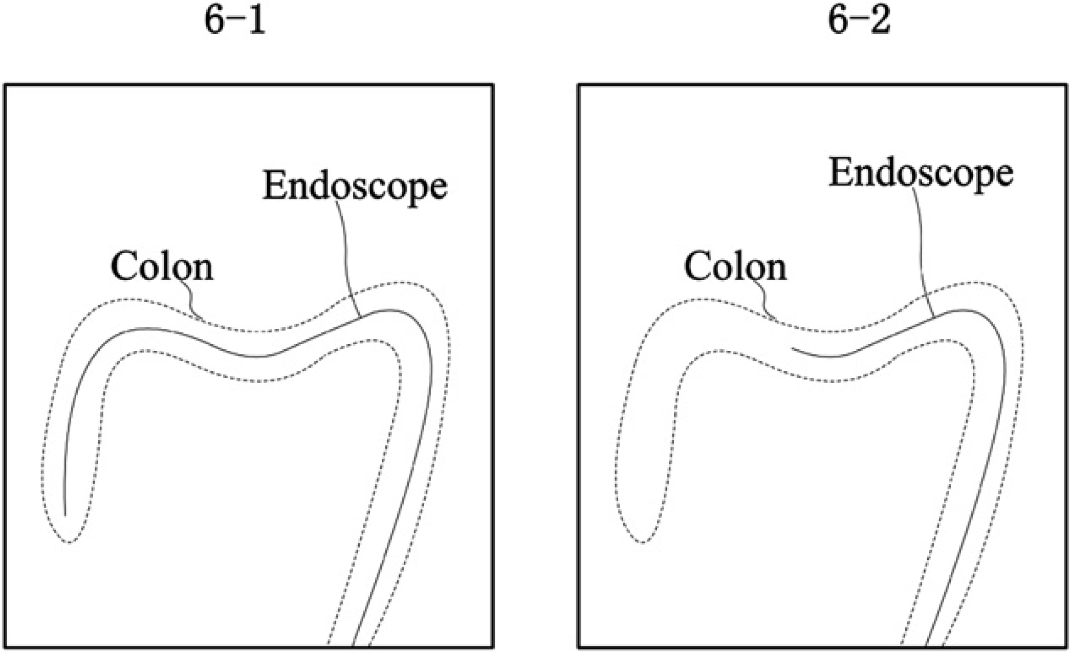
Display of fitted curve of endoscope and virtual colon.
It will be of great help for doctors with less experience in the localization of object observation.
As the three-dimensional position of all emitters can be acquired, the fitted curve of the endoscope can be obtained with the method of B-Spline curve fitting. When the fitted curve of the endoscope, which is inserted in the colon totally is obtained, a hollow transparent cylinder around the fitted curve of the endoscope can be formed as the virtual colon image just as Figure 6-1 shows.
Experiment
The Received Signal
Figures below show the emitters (Fig. 7), receivers (Fig. 8), and circuits for emitter and receiver (Fig. 9), respectively, which are used in our experiment.

Emitters.
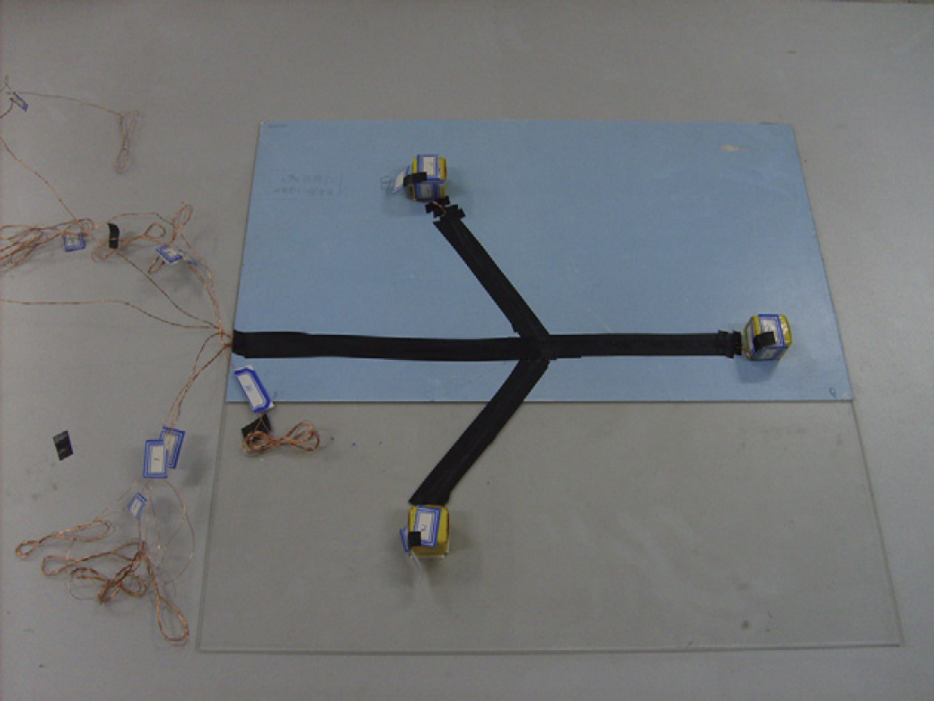
Receivers.
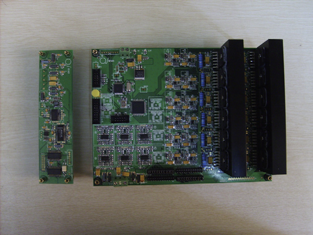
Circuits for emitter and receiver.
Figure 10 shows the wave form presenting the received signal when the distance between the emitter and the receiver is 50 cm. Wave form 1 is the original voltage signal measured in the receiver; Wave form 2 is the voltage signal measured after the original voltage signal goes through process of amplifying and low pass filtering; Wave form 3 is the voltage signal measured after final process, which undergoes band pass filtering based on the process of wave 2.
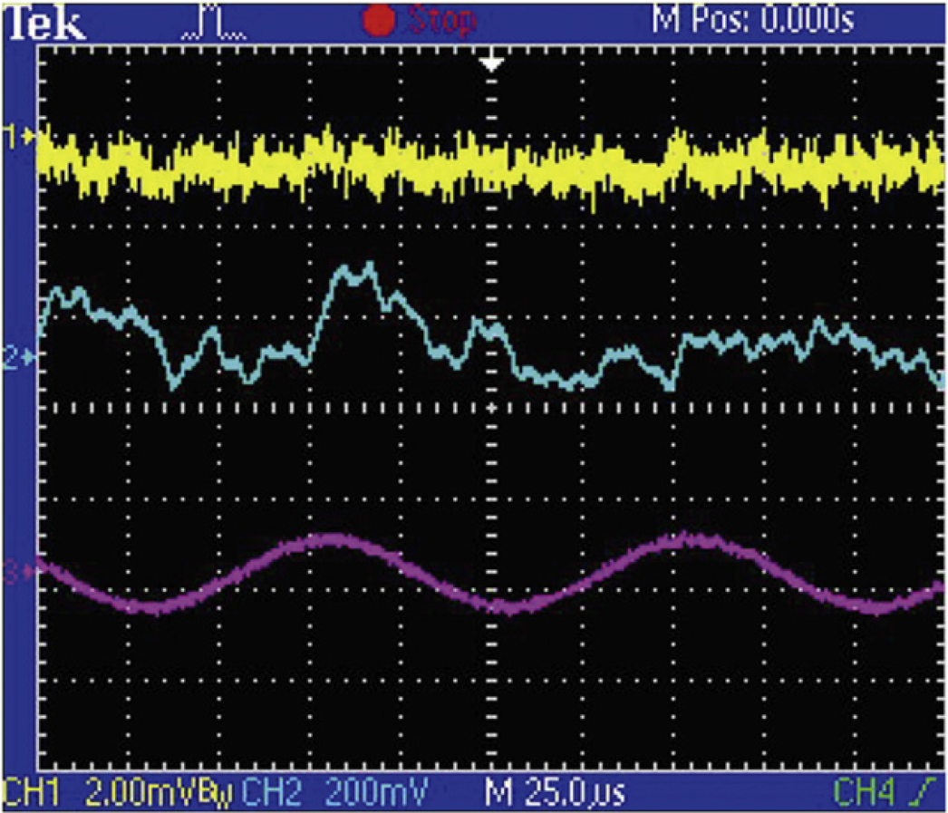
The received signal before and after measurement unit.
Localization Program
We use the localization program based on the fast and simple iterative algorithm to conduct experiments with different distance between the receiver and the emitter in Labview.
In the first experiment, the position and orientation of the emitter is set with x0 = 25, y0 = 14.43, z0 = 0 (the unit is cm) Φ = −30°, θ ≈ 90°. The known parameters are the position of receiver 1 is x1 = 0, y1 = 0, z1 = 0; the position of receiver 2 is x2 = 0, y2 = 50, z2 = 0; the position of receiver 3 is x3 = 25, y3 = 14.43, z3 = 0 (the unit is cm); Vx1 = 1.09 V, Vy1 = 3.325 V, Vz1 = 0.08 V; Vx2 = 0.7 V, Vy2 = −1.35 V, Vz2 = 0.08 V; Vx3 = −2.51 V, Vy3 = −2.65 V, Vz3 = 0.08 V. When these parameters are given, the position program can be run. The position and the orientation of the emitter are x0′ = 26.497, y0′ = 14.001, z0′ = 0 (the unit is cm) Φ′ = −30.530°, θ′ = 90°. Compared with the given position and orientation of the emitter, the result shows that the program works well.
The second and the third experiments change the given position of the emitter with its z coordinate Z bigger to make the distance of the receiver and the emitter larger. The results are shown in Table 1 as below.
The results of the experiment two and three
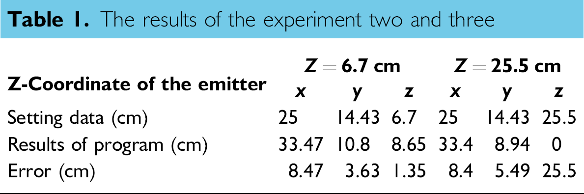
From the Table 1, we can conclude that the error of localization goes greater when the distance between the receiver and the emitter becomes larger. So it is obvious that the method proposed above improves the accuracy.
Conclusion and Discussion
The localization method based on the theory that electromagnetic signal generated by driving electrical coils with sine signals has a specific spatial feature has many advantages such as low cost, none touch, and high accuracy.
In this article, new methods that can improve the accuracy of localization and make diagnosis easier for doctors are proposed. The evaluation of the prototype and related theories are completed. The experiment results show the effectiveness of the proposed methods.
Footnotes
Acknowledgments
Competing Interests Statement: The authors certify that they have no relevant financial interests in this article.