
Abstract
This article gives basic overview of the USS protocol as a communication interface to drive Siemens frequency inverters. It presents our implementation of this protocol into LabVIEW, as there was permanent demand from the community of the users to have native LabVIEW implementation of the USS protocol. It also states encountered problems and their solutions.
Keywords
Introduction
As a part of the apparatus for the valve train measurements on Škoda 1.2HTP combustion engine, we used two-pole, 7.5 kW asynchronous electromotor, frequency inverter SINAMICS G120 and control unit CU240S, all from Siemens AG. The electromotor is used to run the crankshaft of the combustion engine. The inverter, control unit, and electromotor's quadrature encoder assure the vector control of the electromotor. The transition of the torque between the electromotor and the crankshaft ensures ribbed belt (see Fig. 1).
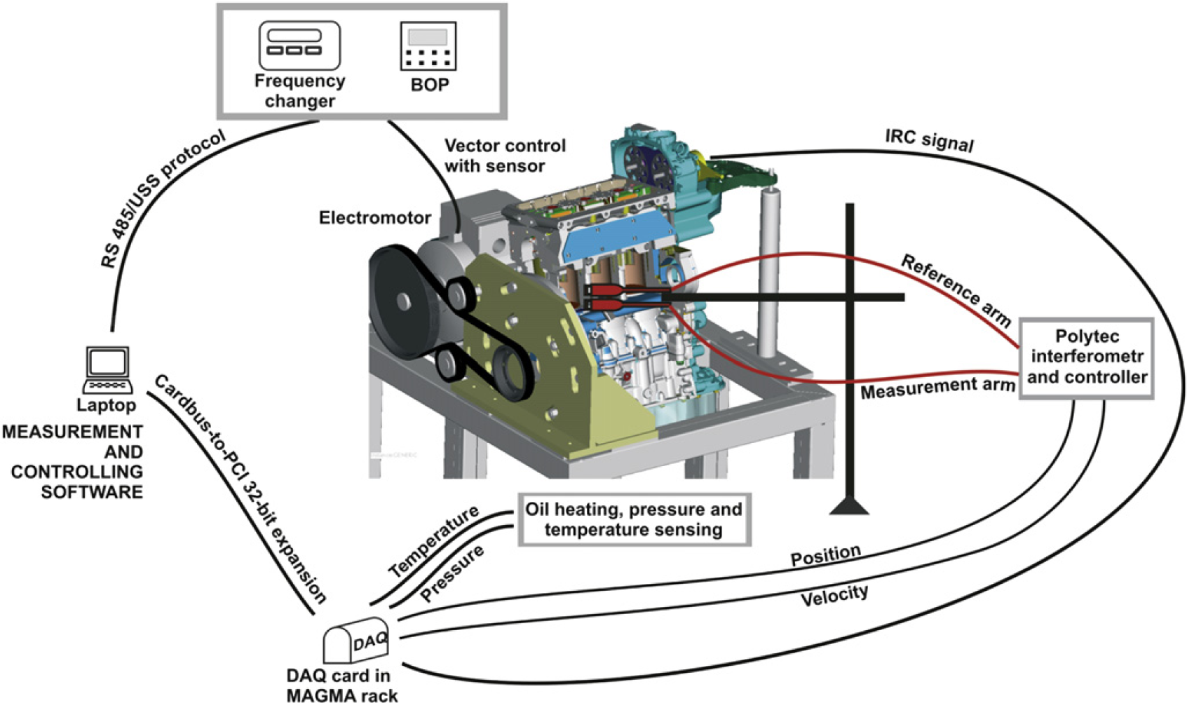
Schema of the apparatus for measurement of the kinematic values of the valve train.
The measurement of the kinematic values of the valve train is performed at predefined spectrum of speeds. For the control and monitoring of the speed, it was necessary to create application for communication with the SINAMICS inverter. During the design of the measurement apparatus, we also had to decide what communication bus and protocol to use. As we develop a computer-based superior system that ensures communication, data acquisition, data processing, and failure handling to perform fully automated measurements and analysis of kinematics of the valve train, it was necessary to choose such an interface that would offer simple but reliable communication between the electromotor and the PC. Siemens offers wide spectrum of connection possibilities of their control units that can operate the SINAMICS G120 inverter, including PROFIBUS (RS485), PROFINET (Ethernet), or USS protocol (RS485).
As we have just simple topology PC(master)–Inverter(slave), we have chosen the standard version of the control unit that allows us to connect over RS485 and communicates via the USS protocol.
We develop the measurement and control application in LabVIEW development environment, so the essential question became the implementation of the USS protocol, as no LabVIEW command libraries are available. Of course, there is an option to use the OPC server either from Siemens or third party, but it requires extra money, installation, and setting of another application and driver not mentioning always the best performance and the necessity to resolve compatibility issues. There was also permanent demand from the community of LabVIEW users to have native LabVIEW implementation of the USS protocol. Based on above written, we decided to write collection of the most common USS commands. The final library was published for public use on National Instruments discussion forum—Motion Control and Motor Drives board.
Basic Protocol Overview
The USS protocol (Universal Serial Interface Protocol) defines an access technique according to the master–slave principle for communication via a serial bus. This also includes the point-to-point connection. Essential features of the USS protocol are as follows:
It supports a multipoint-capable coupling, for example, EIA RS485 hardware; Master–slave access technique; Single master system; Max. 32 nodes (max. 31 slaves); Simple, reliable, telegram frames; Easy to implement; Operation with either variable or fixed telegram lengths.
For detail protocol specifications, see reference 1.
Structure of USS Telegram
Description
Figure 2 shows the structure of a typical USS telegram.
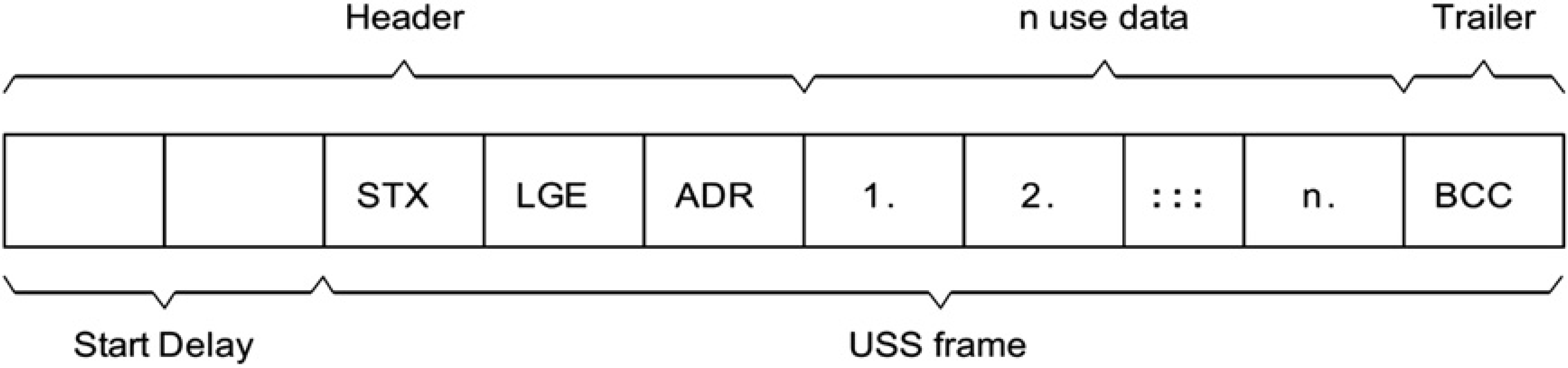
Structure of the USS telegram. 2
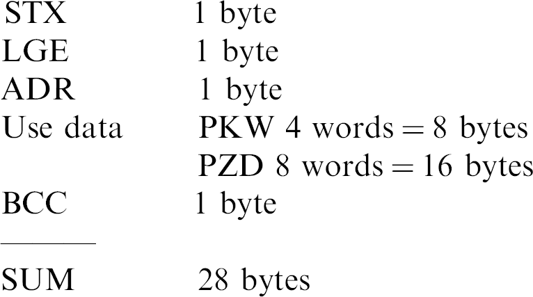
Variable-length telegrams and fixed-length telegrams can both be used. This can be selected using parameters P2012 and P2013 to define the Prozeßdaten (PZD) and Parameter-Kennung-Wert (PKW) lengths, which are the two parts of the use data block. The fixed length sizes we used are shown below:
Start of Text (STX)
The Start of Text (STX) field is a single byte ASCII STX character (0x02) used to indicate the start of a message.
LGE
The Telegrammlänge (LGE) is a single byte field, indicating the number of bytes, which follow this in the telegram. It is defined as the sum of:
Use data characters (quantity n = 24 in our case); Adreßbyte (ADR); and Block check character (BCC).
The actual total telegram length will of course be two bytes longer, as STX and LGE itself are not counted in the LGE.
ADR
The ADR field is a single byte containing the address of the slave node (e.g., inverter) and additional telegram settings (e.g., broadcast, mirror telegram).
BCC
BCC means block check character. It is an exclusive OR checksum over all telegram bytes except the BCC itself.
Structure of Use Data Block
The use data area of the USS protocol is used for transferring the application data, which are the earlier-mentioned parameter channel PKW and the process data-channel PZD as can be seen in the Figure 3.
Structure of the use data block as we used it.
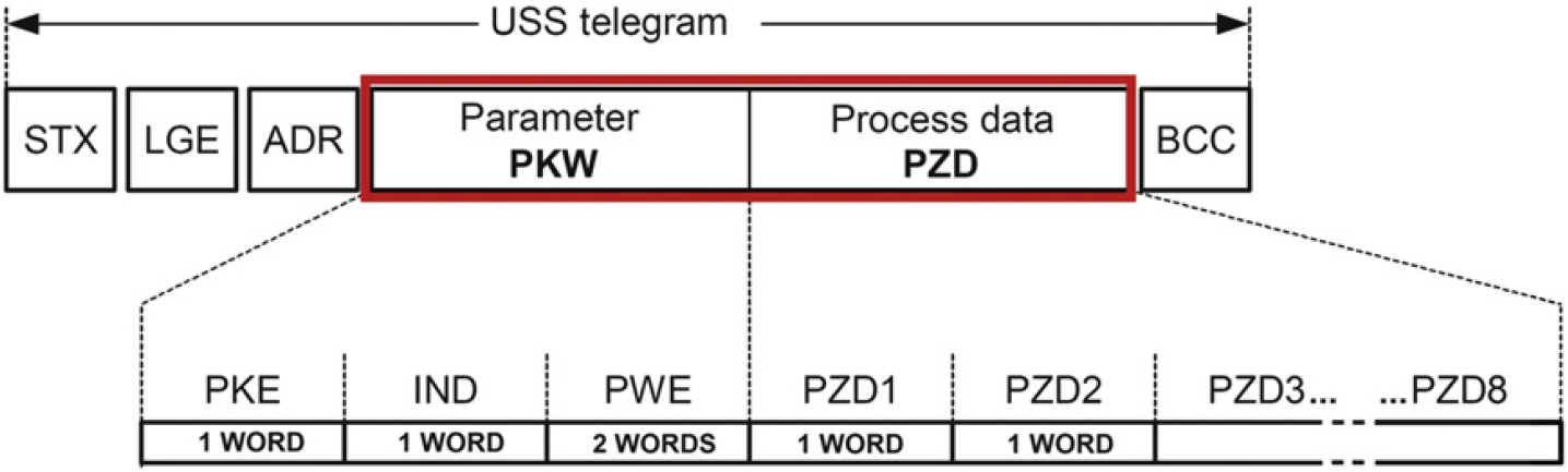
Parameter Channel PKW
The parameter channel can be used to monitor and/or change any parameter in the inverter. The inner structure is not trivial and can be looked up for details in the referenced literature. 1,2 Simply, this block is used to enter the number of the parameter we want to operate (read or set), index as the basic parameters have different values for each Command (CDS) and Drive Data Set (DDS), 3 and the operation we want to perform (request or response identifier).
For acyclic communication via USS, the number of Parameterwert (PWE)s (third and fourth words) can vary. For 16-bit values, one PWE is required. If 32-bit values are exchanged, two PWEs are required. As we set the PKW to constant length of four words for our purposes, it means that the PWE area will always occupy two words. Then, a 32-bit parameter value comprises PWE1 (high-order word, third word) and PWE2 (low-order word, fourth word). A 16-bit parameter value is transferred in PWE2 (low-order word, fourth word). PWE1 (high-order word, third word) must be set to 0 in this case.
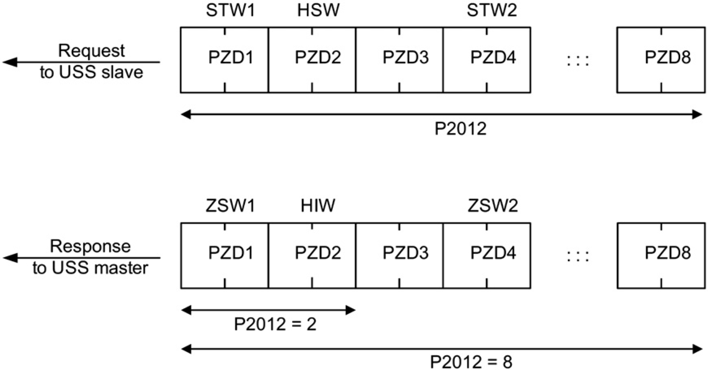
Process Data Channel PZD
In this area of the telegram, process data (PZD) are continually exchanged between the master and slaves. It contains the signals required for the automation. Dependent on the direction, the process data channel contains data for a request to the USS slaves or for a response to the USS master. In the requests are control words and setpoints for the slaves, and in the responses are status words and actual values for the master. The number of PZD words in a USS telegram is determined by parameter P2012. First two words are as follows:
Request to USS slave: Control word 1 (STW1) and main setpoint (HSW) Response to USS master: Status word 1 (ZSW1) and actual value (HIW)
If P2012 is greater or equal to 4, the additional control word (STW2) is transferred as the fourth PZD word (default setting) (Fig. 4).
Process data-channel structure. 2
As we were also interested into continuous monitoring of torque and power of the electromotor, we set the PZD length to eight words, and by the mean of BICO technology, we linked some of the extra words so the channel structure was set as follows:
PZD1 = STW1/ZSW1 PZD2 = HSW/HIW PZD3 = not linked PZD4 = STW2/ZSW2 PZD5 = not linked PZD6 = not linked PZD7 = r0031 = Act. filtered torque PZD8 = r0032 = Act. filtered power
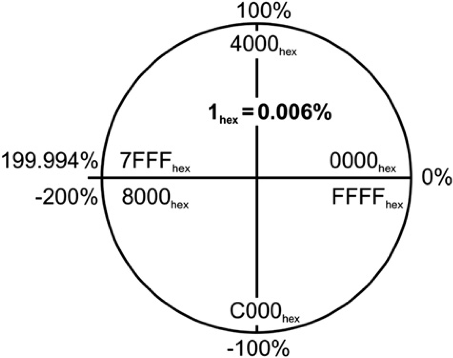
Actual values of parameters such as setpoint, frequency, torque, and power are read through normalized values. The range can be from −200% (8000hex) to 199.99% (7FFFhex) of the reference value. It is therefore very important to set the reference values in expected range of the measurement to prevent exceeding. The range is coded as word (U16). It means that we get 400/216 levels. That gives the resolution of 0.006% (Fig. 5).
Valid range and U16 coding of normalized values.
Implementation of USS Protocol into LabVIEW
As mentioned earlier, there was a constant need for creation of native LabVIEW API covering the most common commands and routines and enabling easy creation of new ones. We decided to develop LabVIEW USS protocol library that would serve for purposes of our measurements on the combustion engine. The final result was published for public use on National Instruments discussion forum—Motion Control and Motor Drives board.
It is important to emphasize that the programmed library expects the length of the PKW to be set to four words (P2013) and PZD to eight words (P2012); otherwise, the communication will fail. As described in previous chapter, it also counts with PZD7 word to be linked to torque and PZD8 to the actual power of the electromotor.
The overall structure of the library respects the common rules of creating drivers or API in LabVIEW. The virtual instruments (VIs) on the hard drive are divided into four main folders: Commands, HighLevel, LowLevel, and Examples. The folder Commands contains our implementation of the basic commands that probably most of the users will take an advantage of. HighLevel and LowLevel folders consist of the support VIs that were used for the commands creation and can be used for the creation of new ones. Each of the commands is equipped with an icon that from a quick glance offers the basic information about the command properties. If it is Read or Set command can be determined from the color (Read = red, Set = blue, Special = cyan). Each of the commands is also equipped with short description information that helps to understand the aim of the command.
The Command Structure
We will describe the structure of the commands using one of the very basic ones—P1082, Maximal Frequency—Set. Other commands have structure, which more or less conforms to this one.
Each of the encapsulated commands has connectors (Fig. 6) to enter the address of the inverter, VISA resource name that carries the information about the opened communication channel (baudrate, parity…), Index of the parameter we want to set (as mentioned earlier there can be different values for each CDS/DDS), and value to be set (read value in case of Read commands) showing also the default value. Error handling is present and thus if error occurs in any of the VIs, the following ones will be skipped and the error reported immediately. The remaining parameters are Timeout and RepCount, which are the parts of the resending algorithm for handling communication outages as described in the chapter Communication outages on RS485.
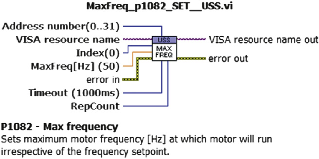
Connectors of single command and sample of description.
Inner command structure consists of five parts and can be seen in the Figure 7. The first element of the cluster marked (Fig. 7—1) sets whether the PKW part should be present in the telegram. If set to false, it automatically sends empty (=zeros) PKW channel. Next element is the request identifier specifying the desired action to perform. The parameter number, index, and value of the parameter follow.

The inner structure of USS command.
The first element of the cluster marked (Fig. 7—2) sets whether the PZD part will be used. Next element determines whether the inverter should be switched ON/OFF. Following elements are the inversion of the setpoint and the desired value of the setpoint itself (normalized value). Both mentioned clusters are type definitions created for easy manipulation and possible custom changes.
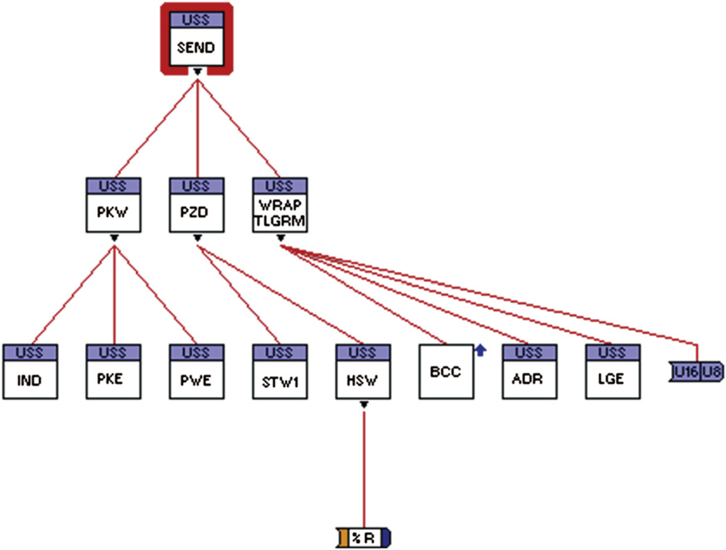
Hierarchy of Send_Telegram__USS.vi.
The VI Send_Telegram__USS.vi (Fig. 7—3) handles creation of the telegram to be sent according to the protocol specifications stated in the previous chapters and referenced literature. 1 The hierarchy of the VIs can be seen in the Figure 8. The purpose of each part can be determined from the SubVI name. The SubVIs can be found in the HighLevel or LowLevel folders depending how deep in the structure they are located. As a result, the exact telegram bit structure is composed and made ready to be sent to the inverter.
The next step (Fig. 8—4) is to send the telegram and receive the answer from the inverter. After sending, the port is continuously scanned. The received answer is parsed. BCC, the length and the presence of STX are checked. If the answer has unexpected format or is not received at all, the resending algorithm is applied or an error is reported. All mentioned is programmed in the Comm__USS.vi. In the Figure 9, the block diagram and the VI hierarchy can be seen for better understanding. Respecting the data flow, the execution starts with the LabVIEW write primitive then continues to the Receive_Telegram.vi that continuously scans the port and as a next step the possible error checking is wired. The code is encapsulated with a while loop so that the actions can be repeated if there is a need to resend the telegram.
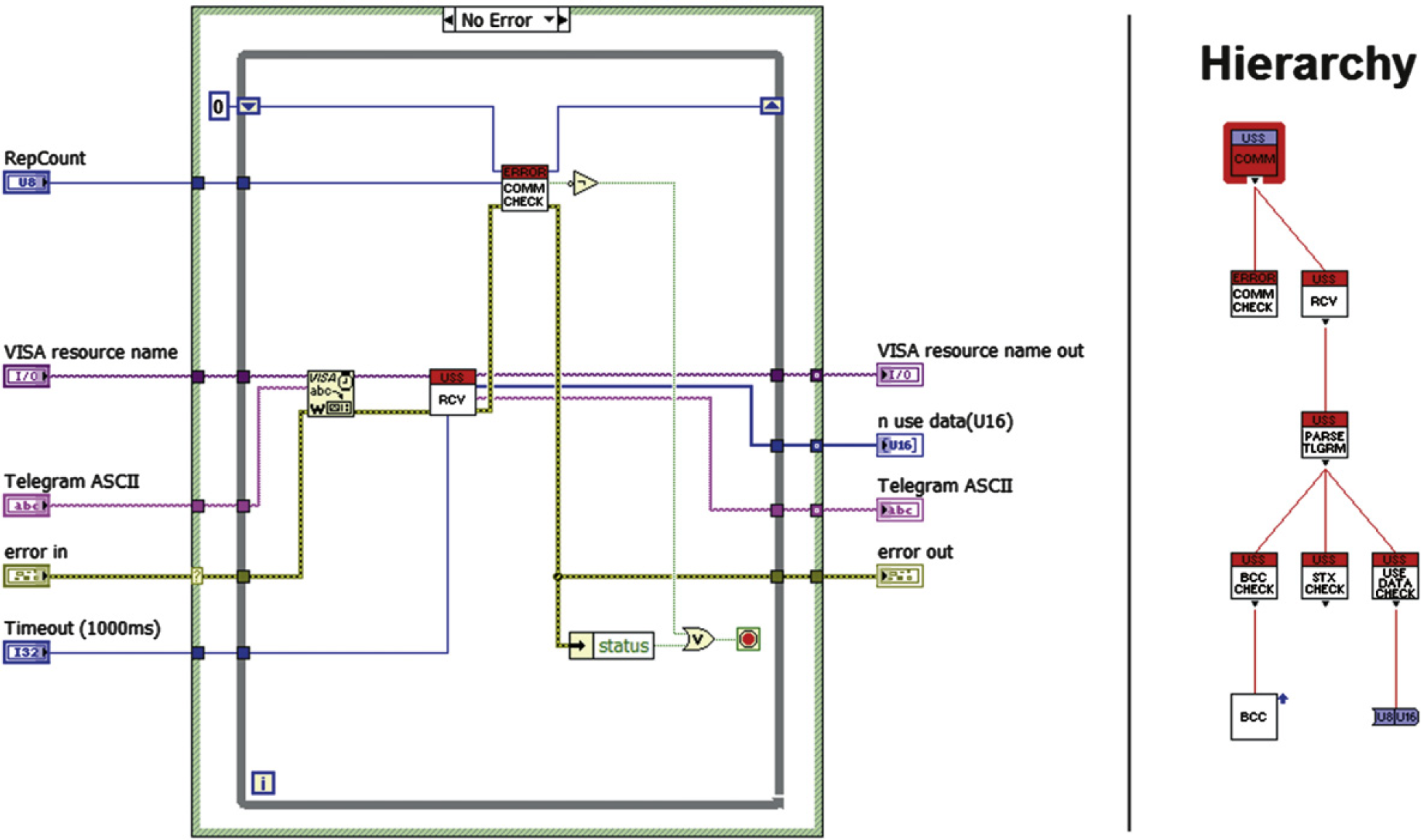
Block diagram and hierarchy of Comm__USS.vi.
The last part (Fig. 7—5) is focused on obtaining the important information from the received answer. In case of basic commands, it will be only the value we set/write and the inverter state, but in case of the setpoint regulation we will also get the actual status words and the linked parameters (in our case frequency, power, and torque).
Communication Outages on RS485
Another problem that we came across was the random communication outages. The inverter time to time did not reply when a telegram was sent to it, most likely because it did not receive the request or the request arrived distorted, and thus it was refused.
We used RS485 (EIA-485) to exchange the telegrams. RS485 is a two-wire, half-duplex, multipoint serial communication channel. As it uses a differential balanced line over twisted pair, it can span relatively large distances (upto 1200m). Ideally, the two ends of the cable will have a termination resistor connected across the two wires. Without termination resistors, reflections of fast driver edges can cause multiple data edges that can cause data corruption. Termination resistors also reduce electrical noise sensitivity due to the lower impedance. Termination is usually required for long distances and high speeds. The length of the cable we used was about 4 m and thus we did not terminate the line at first. Nevertheless, random outages in the communication appeared. We thought that the termination might help and we switched ON the termination DIP switch on the CU240S and connected the termination 220Ω resistor across the two signal wires on the opposite end of the cable (schema depicted in Fig. 10).
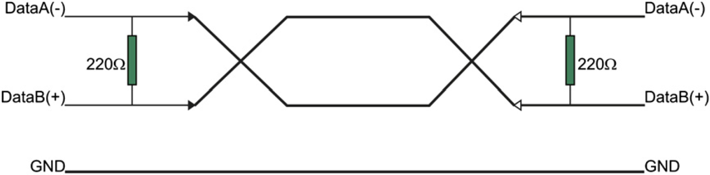
Termination schema.
We also connected the bias resistors, but none of those adjustments helped to prevent the communication outages.
As those problems appeared randomly but rarely, we decided to implement simple resending algorithm (Fig. 11) to the API. As it was described in the chapter The Command Structure, each command VI is equipped with connectors Timeout and RepCount. Timeout defines the time during which the program has to receive the valid response. If the valid response does not arrive, it will resend the data in predefined number of attempts. If none of those attempts succeeds, the error is reported indicating that there is a major problem in the communication.
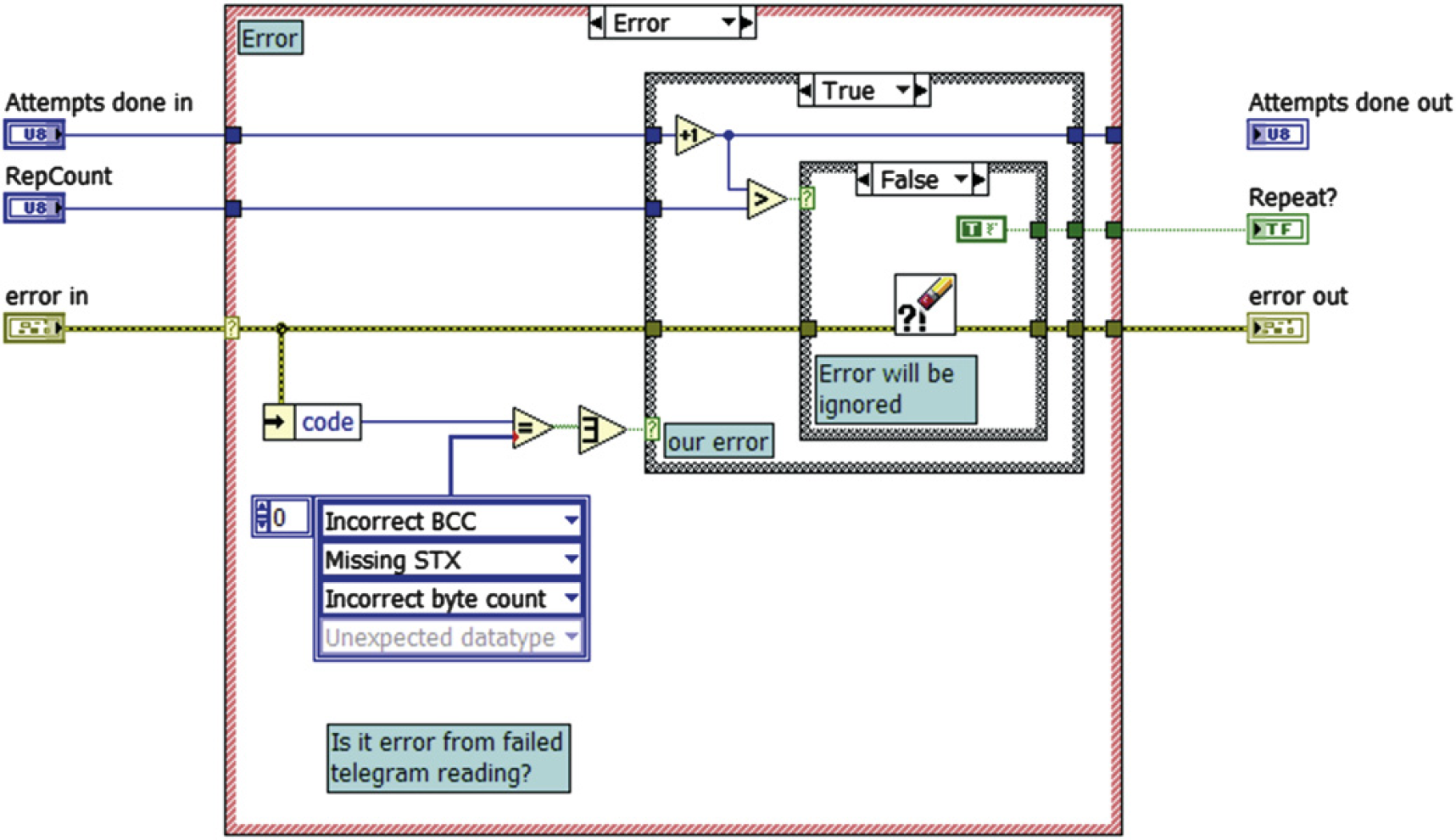
The core of the resending algorithm.
Slave Response Latency
During the period of testing programmed USS library, we also encountered unexpected behavior of the response telegrams send by the inverter.
Communication with Siemens inverters is focused on cyclic communication. As the typical scenario is for the master (typically a PLC) to continuously scan multiple slave devices, command data refresh rate is more important than response data latency. Rather than make the master wait for the slave to formulate a reply on every pass, the slave has the reply ready for the master based on the requested data in the previous pass. This way communication time is kept to a minimum.
This behavior unfortunately might complicate the acyclic communication when we just want to set some parameter of the inverter. The parameter will be changed correctly (if no fault or error occurs), but the immediate response of the slave will consist of the value of the previously set/requested parameter. The same and even more confusing situation occurs when requesting only value of some parameter. Instead of sending the reply to requested parameter, it sends reply to the previous request. For example, if we asked the value of parameter P1082 (maximum motor frequency) sending following telegram (PKW = 4, PZD = 8):


we would receive the answer with the value of parameter P1080 (minimum motor frequency) that we requested before:


This behavior is necessary to take into account when dealing with any implementation of the USS protocol. If you parse the entire reply, you always know to which parameter you apply the data, but it won't probably be the same you set/asked.
Conclusion
We created API for handling the communication with the family of SINAMICS inverters via the USS protocol from superior PC-based system. The library was tested with the G120 inverter and control unit CU240S, and it proved its reliability. As it was given for public use, other users already reported its usability with other types although some minor changes had to be made in some cases. The creation of the library was motivated by the nonexistence of any implementation of the mentioned protocol into LabVIEW, which is nowadays probably the most spread environment for carrying out custom measurements and PC-based automation. The library is also supplemented with few examples, where one presents simple application for driving the electromotor and setting the very basic parameters programmatically.
Competing Interests Statement: The authors certify that they have no relevant financial interests in this manuscript.