
Abstract
The Electron Microscopy Proteomic Organellar Preparation (EMPOP) robot is a tool for high-throughput preparation of subcellular fraction samples for electron microscopic identification. It provides a means of validating subcellular sample purity and confirming protein localization needed for organellar proteomics.
The device handles all chemical and mechanical manipulations required to prepare organelles for electron microscopic examination. It has a modular, integrated design that supports automated filtration, chemical processing, delivery, and embedding of up to 96 subcellular fraction samples in parallel. Subcellular fraction specimens are extremely fragile. Consequently, the system was designed as a single unit to minimize mechanical stress on the samples by integrating a core mechanism, composed of four modular plates, and five support subsystems: (1) a cooling platform, (2) an automated fluid handling subsystem, (3) an electromagnetic arm, (4) a plate transfer platform, and (5) a 5-axis motion control system (X, Y, Z, θ, ø).
System control is fully automated to provide standardized, reproducible subcellular fraction sample processing while maintaining flexibility for adjustment and recall of instrumentation and process operational parameters. To achieve this, the control software was built on two coordinated levels: (1) a user interface for system testing, calibration, setup, and process monitoring and (2) low-level real-time control routines.
The EMPOP robot provides, for the first time, massive, parallel electron microscopic screening and quantitative analysis of subcellular and protein targets necessary for high-throughput proteomics.
Keywords
Introduction
As with other systems biology research efforts, proteomics 1 requires scaling of “bench” methods to support automated, high-throughput sample preparation and screening. 2 –6 The subcellular- or organellar-based approach to proteomics 7 –10 requires electron microscopy to (1) validate purity of subcellular sample preparations by morphometry and (2) confirm protein localization in isolated organelles. 11
Currently, these samples are prepared manually; organelles obtained by subcellular fractionation techniques 12,13 are first filtered to deposit and localize the sample onto a charged filtration membrane 14 followed by a complex chemical processing protocol. 15 This manual protocol is laborious, time consuming, and difficult to reproduce.
Commercial laboratory automation systems, commonly used to assay or isolate macromolecules, are not appropriate for automated preparation of organelles. Methods and devices specific to processing subcellular fraction samples for electron microscopic analysis require an integrated, modular, and multifunctional platform for (1) gentle handling of organelles, (2) quantitative control over sample filtration and transfer, and (3) capture and isolation of processed samples for embedding and retrieval.
Therefore, we have developed the Electron Microscopy Proteomic Organellar Preparation (EMPOP) robot to expedite sample preparation and improve reproducibility. The objective is to prepare samples suitable for direct quantitative comparison of results for electron microscopic characterization and analysis of isolated organelle purity and location of subcellular and protein targets by quantitative immunolabeling.
Mechanical Design and Operation
The three main design criteria for the EMPOP robot are as follows: (1) a fully automated system, (2) gentle treatment of the biological samples, and (3) quantitative control and documentation over all individual steps and subprocesses. Consequently, the subsystems are integrated into an autonomous instrument that minimizes mechanical perturbations and maximizes intercompatibility of chemical, biological, and mechanical parameters.
Core Mechanism
All automated work done by the EMPOP robot centers around a modular system of processing plates that forms the robot's core mechanism (Fig. 1). This provides the flexibility for automation of the complex chemical protocols necessary for subcellular sample processing as well as integration with the other subsystems of the automated design.
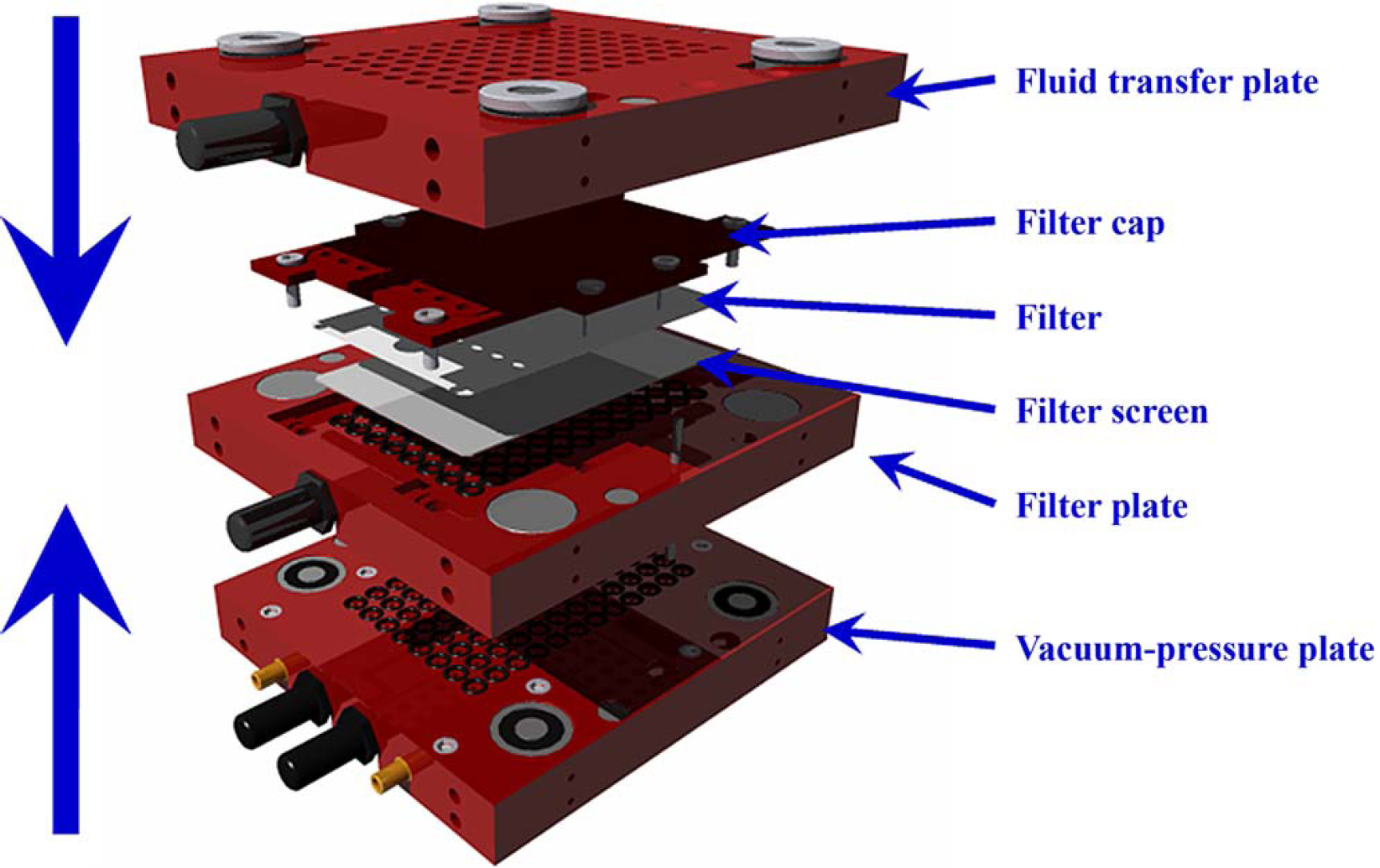
CAD rendering illustrating an expanded view of the processing configuration of the core mechanism.
The four stackable and reconfigurable plates that make up the core mechanism are as follows: (1) a fluid transfer plate providing individual fluid reservoirs for each of the 96 samples, (2) a filter plate holding the filter membrane-bound samples throughout processing, (3) a vacuum-pressure plate for filtration of the subcellular fraction samples onto the filter membrane and delivery of the processed samples, and (4) a retainer plate holding a 96-well plate of polymerized embedding solution for the final steps of processing and collecting samples at the end of the automated protocol.
Three plate configurations for processing, delivery, and embedding of samples are used throughout this protocol. In each configuration, the plates are held firmly together and sealed by eight high-power permanent magnets built into the filter plate, which is always located in the center of the plate configuration. All other plates contain corresponding electromagnets for automated decoupling. Locating pins and corresponding holes are used to align the plates. Miniature magnets and magnetic proximity sensors embedded in the plates transduce plate alignment to the robot motion controller.
The sequence of sample processing is complex and involves 20 stages as shown schematically for a single channel of the core mechanism (Fig. 2). The preliminary steps in the operation are to be performed manually; first, the plates are magnetically coupled to form the processing configuration used throughout most of the automated procedure, and then, the biological samples are placed into individual wells of the coupled configuration. All subsequent manipulations in the processing protocol are automated. The process begins with filtration of the subcellular fraction samples onto a charged filter membrane. Processing reagents are dispensed and aspirated to and from the 96 individual wells; the cycle of dispensing, incubating, and aspirating chemicals is repeated as many times as is necessary to complete the protocol.
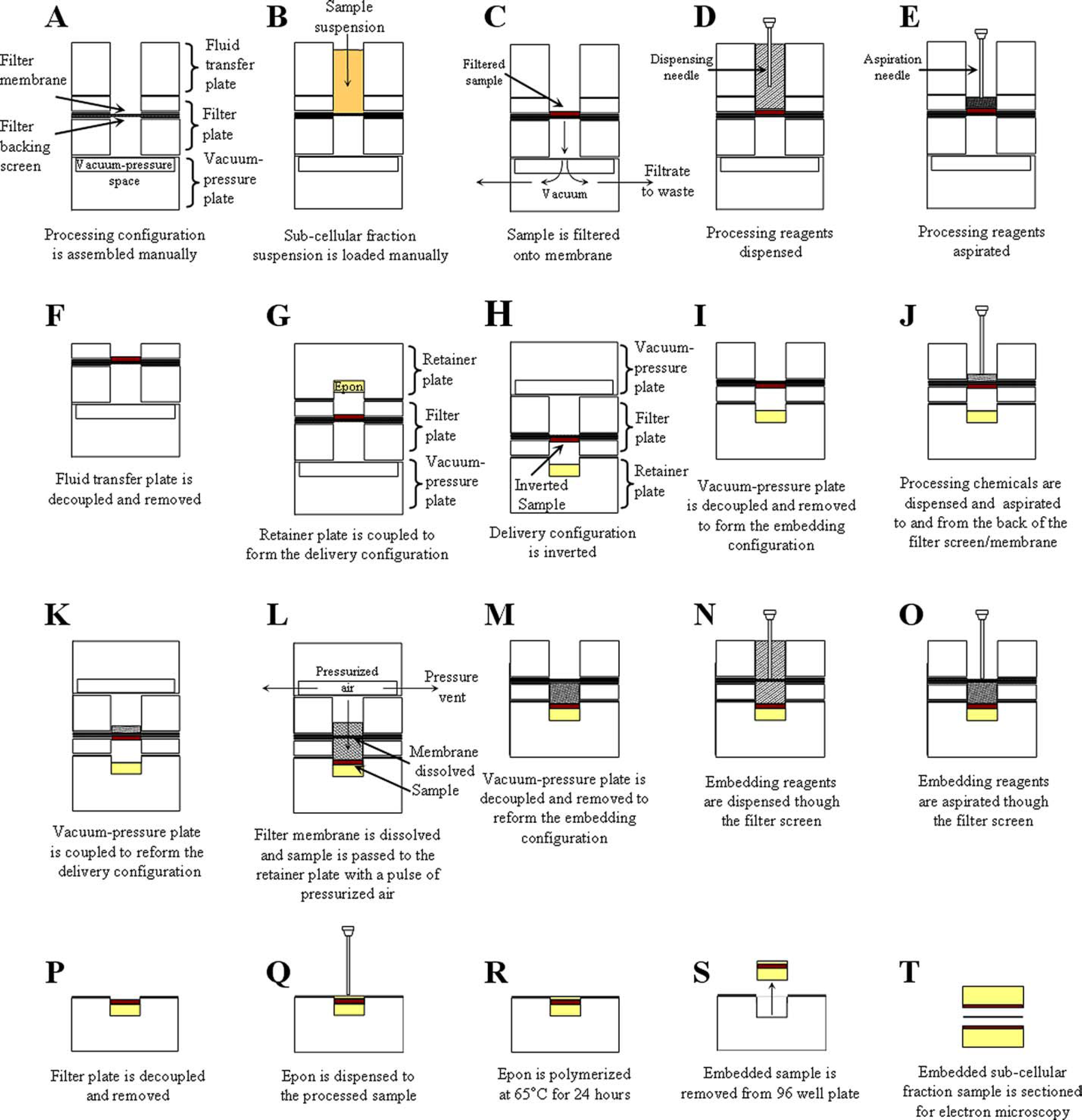
(A-T) Cross-sectional illustrations of a channel in the EMPOP robot core mechanism during automated subcellular fraction sample processing. (A-E) Sample filtration and chemical processing within the processing configuration, (F-H) formation of the delivery configuration, (I-L) formation of the embedding configuration and transfer of processing samples to the retainer plate, (M-O) embedding steps of the processing protocol, (P-R) disassembly of embedding configuration and final steps in embedding, and (S-T) collection of processed and embedded sample and presentation for microscopic analysis.
The two other configurations are used in the last steps of chemical processing, transferring of the samples to the retainer plate, and finally, embedding of the samples. An electromagnetic arm, used for the positioning of all the plates, removes the decoupled fluid transfer plate from the processing configuration and replaces it with the retainer plate to form the delivery plate configuration. This configuration is inverted and the vacuum-pressure plate is temporarily removed (to form the embedding plate configuration) for further processing and to dissolve the filter membrane. Next, the processing samples are transferred to the 96-well plate from the replaced vacuum-pressure plate by pressurized air. Once processing is complete, the plates are decoupled and the embedded subcellular fraction samples are collected for electron microscopic analysis.
Support Subsystems
Figure 3 illustrates the complete robot and its five support subsystems for (1) cooling, (2) fluid handling, and (3–5) positioning.
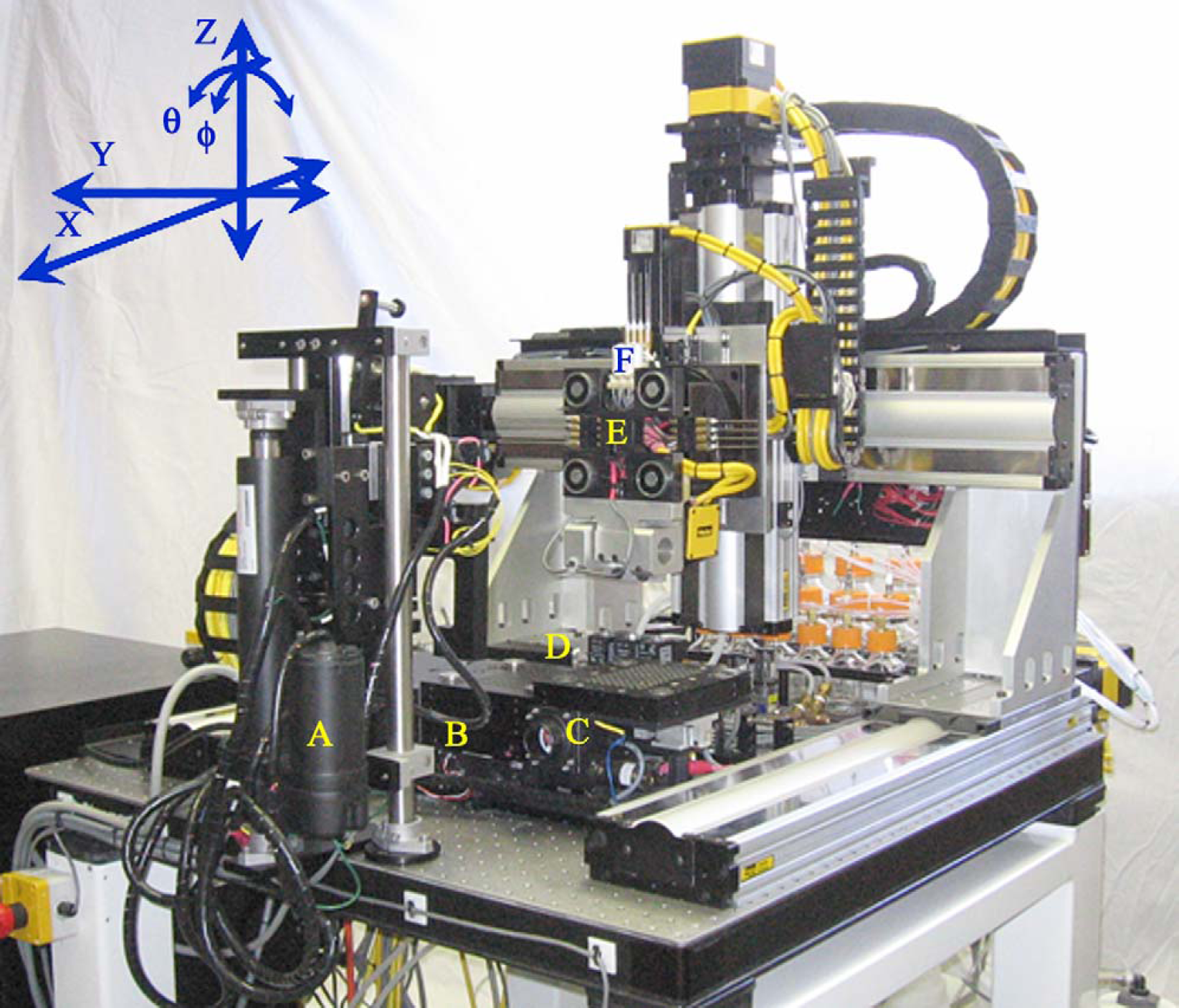
The EMPOP robot. The six robot components are (A) transfer platform, (B) core mechanism, (C) cooling platform, (D) wash station, (E) electromagnetic arm, and (F) dispensing needle manifold. Note: The fluid handling system is mounted at the back of the robot and therefore not visible.
The cooling platform maintains the core mechanism at a constant 4°C during a sample preparation run. The thermoelectrically cooled walls of this component compress and retract for contact and clearance, respectively, with the core mechanism. The fluid handling subsystem comprises three subsections for (i) processing reagents, (ii) pressurized air, and (iii) waste.
A panel of miniaturized liquid handling components is mounted to the back of the Y-axis of the motion control system. Directional control of processing reagents is achieved using four banks of 2- and 3-way solenoid valves interfaced with directional manifolds. Movement and mixing of reagents is achieved with two stepper pumps coordinated with the solenoid valves to deliver processing reagents to the core mechanism via dispensing needle manifolds located on the θ-axis of the robot. A manifold for pressurized air and vacuum is mounted to the back of the antivibrational table where two small air reservoirs are charged with an interfacing air compressor. Manifolds of solenoid valves (direct acting and proportional) and pressure transducers, mounted in line with the reservoirs, provide directional control of the robot's aspiration needle manifold, needle clean station, and vacuum-pressure plate. The waste removal system utilizes vacuum to aspirate spent processing reagents from the core mechanism and clean the aspiration and dispense needles at the robot's clean station. The three positioning support subsystems are (3) an electromagnetic arm, (4) a transfer platform, and (5) a motion control system. The electromagnetic arm is located on the φ-axis of the motion control system. It retrieves, places, and rotates the plate configurations on the cooling platform and transfer platform with four high-power electromagnets per face and 90° of servo-controlled motion. The transfer platform retains the inverted core mechanism temporarily, whereas the motion control system and electromagnetic arm are repositioned to retrieve it from the opposite face to be replaced on the cooling platform. The transfer platform geometry permits direct passage of the electromagnetic arm, and two linear actuators position the platform vertically and retract into a stowed position when not in use. Integration is completed by a serially coupled, 5-axis servo motion control system for transfer of individual plates or configurations of the core mechanism as well as coordinated motion with fluid handling tools.
Automated Control
Figure 4 is a block diagram of the following controlled processes of the EMPOP robot: (1) robotic positioning, (2) plate alignment, (3) sample filtration, (4) processing reagent dispensing, (5) waste aspiration, (6) dispense needle wash, (7) dispense needle dry, (8) sample delivery, and (9) temperature control. Process parameters are set by the operator on the host computer/motion controller. Upon execution of a process, the motion controller and its associated digital and analog input/output (I/O) modules drive the events.
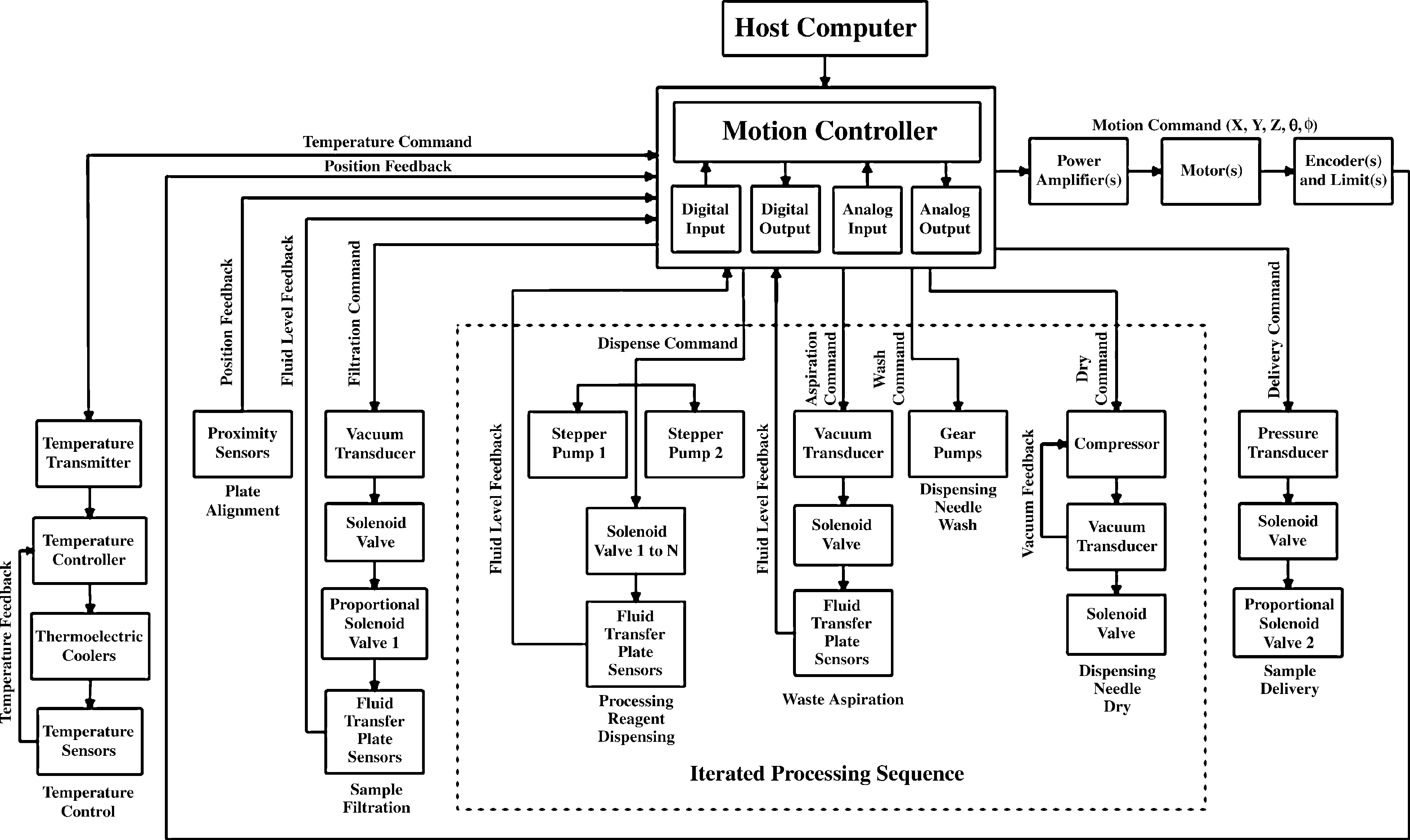
Block diagram illustrating the organization of all controlled processes in the EMPOP robot.
Processes 2–6 are organized to be nested within the feedback loop for robotic positioning (the outer loop) and occur only if the loop is complete. Furthermore, events that take place on an iterated schedule are enclosed within the dotted line depicted in Figure 4, except sample filtration and sample transfer that occur once within an automated run.
A two-tier programming scheme (Fig. 5) coordinates the user interfaces with the automated control routines. The upper level graphical user interfaces (GUIs) were developed using Microsoft Visual Basic and designed for “friendly and flexible” operator use. The GUIs call libraries of lower level firmware routines, which are organized to follow the control logic illustrated in Figure 4 and stored within the robot's motion controller. These libraries, developed using Compumotor Motion Planner, 16 are divided into six levels of progressively more specific routines for events, subevents, and control of individual subcomponents.
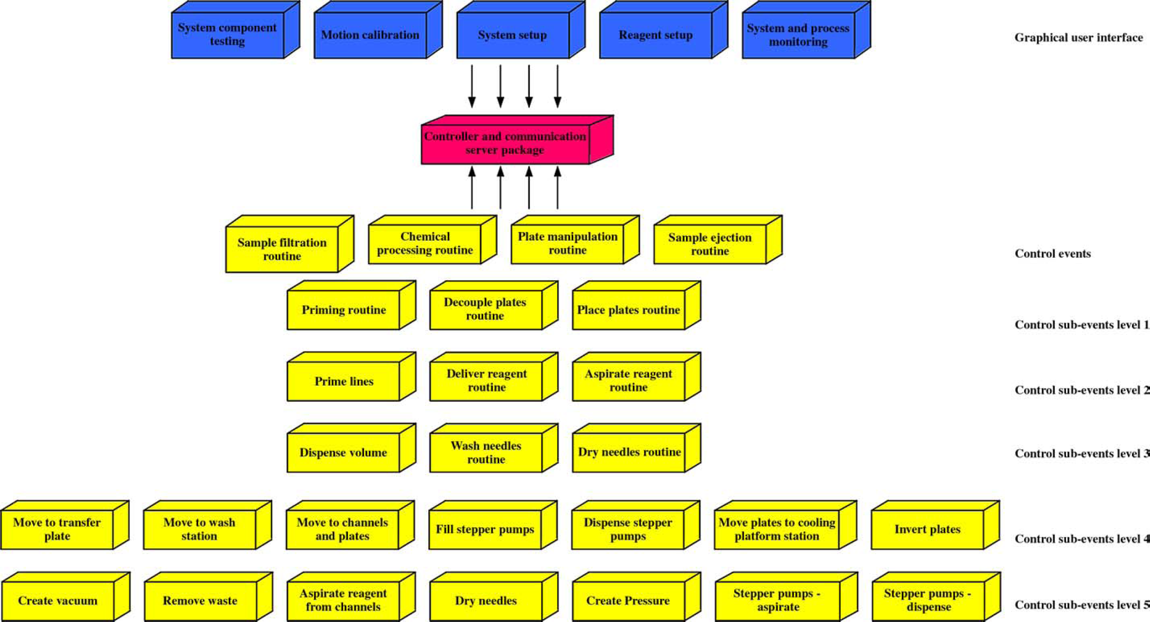
Programming scheme employed for coordination between the upper level GUIs (blue) and lower level automated control routines (yellow). A communication server package is used to communicate information between the upper and lower level programs via the controller (red).
The user interface comprises five GUIs for testing, calibration, setup, and monitoring: (1) system component testing, (2) motion calibration, (3) system setup, (4) reagent setup, and (5) system and process monitoring. The GUIs allow approximately 100 system parameters (sample locations, number of needles, wash frequency, dispense volumes, number of iterations, incubation times, pressure levels, etc.) to be configured before and modified during an automated run. Because the number of parameters is large, the user can either manually set each parameter or load all the parameters using a predefined configuration file. The configuration file allows the operator to repeat an automated run using an identical parameter set. The GUIs also enable creation of a log file during a process for comparison of robot performance from run to run.
The GUI for system and process monitoring (Fig. 6) allows the status of each processing step to be continuously updated and provides a view of the system levels for temperature, pressure, and vacuum. Furthermore, the operator has the option of progressing sequentially through each processing step. This option enables the users to determine the optimal processing parameters for each sample type by giving them complete control over the automated protocol.
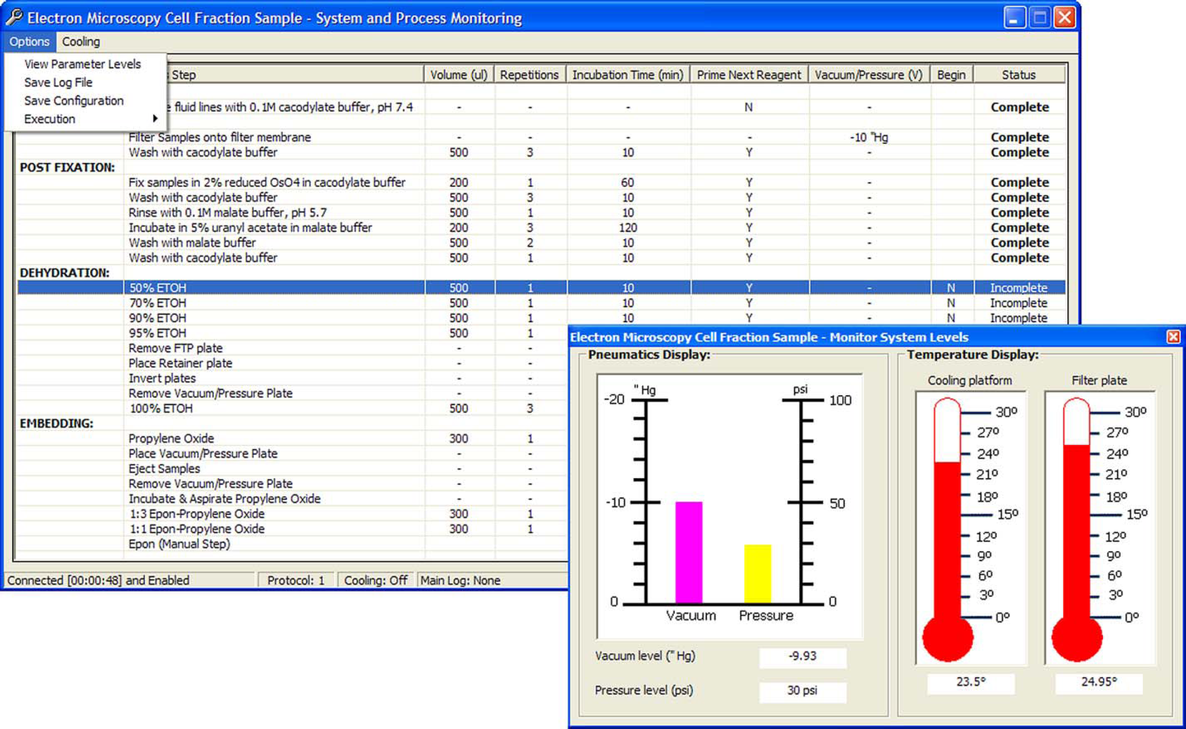
System and processing GUI of the EMPOP robot.
A communication server package 17 interfaces the upper and lower programming levels. This server permits the upper level GUIs, by way of the robot's controller, to pass system parameters to the lower level control routines. Similarly, the lower level routines use the server to send performance data to the upper level programs for documentation in the log file.
The robot's controller oversees communication between the two program levels and monitors system function during a run by scanning pertinent I/O channels every 2 ms. Errors or irregularities detected are self-corrected by calling upon lower level routines (gross errors encountered by the controller result in a system fault).
The lower level programs control motion, fluid handling, and temperature subsystems. These generic and modular routines can easily accommodate parameter changes made by the user in the upper level programs. The GUIs of the upper level can only call upon the first layer of control routines (events) of the lower level. Within the lower level control programs, each layer can call routines in any of the lower layers.
Discussion
The EMPOP robot was created as a high-throughput tool for organellar proteomics to reproducibly prepare 96, high-quality, embedded subcellular fraction samples, unattended, in less than one working day, effectively reducing the time and labor by approximately 1000 fold. Furthermore, the samples prepared by the automated system will fulfill the three needs not met by any commercial apparatus: (1) characterization of isolated organelles for their purity by ensuring a random sampling and direct comparison of 96 identically processed samples, (2) quantitative parallel immunolabeling for the location of novel and unexpected proteins characterized by mutations and identified by proteomics, and (3) utilization of morphometry on these preparations to define the purity of samples and antigen chemistry (antigens/μm 2 of a defined membrane or within a compartment or organelle).
Acknowledgments
This work was supported by the Natural Sciences and Engineering Research Council of Canada (NSERC), the Canadian Institutes of Health Research (CHIR), Genome Québec (GQ), and Genome Canada (GC). The authors would also like to thank Ali Fazel and Line Roy of the Montreal Proteomics Network for their expertise and insightful discussions.