
Abstract
This paper presents a cooperative control strategy for a team of aerial robotic vehicles to establish wireless airborne communication networks between distributed heterogeneous vehicles. Each aerial robot serves as a flying mobile sensor performing a reconfigurable communication relay node which enabls communication networks with static or slow-moving nodes on gorund or ocean. For distributed optimal deployment of the aerial vehicles for communication networks, an adaptive hill-climbing type decentralized control algorithm is developed to seek out local extremum for optimal localization of the vehicles. The sensor networks estabilished by the decentralized cooperative control approach can adopt its configuraiton in response to signal strength as the function of the relative distance between the autonomous aerial robots and distributed sensor nodes in the sensed environment. Simulation studies are conducted to evaluate the effectiveness of the proposed decentralized cooperative control technique for robust communication networks.
Keywords
Introduction
Cooperative autonomous operations by teams of heterogeneous vehicles such as aerial, surface, and underwater robots will increase the functionality of distributed sensing for shared situational awareness, surveillance and target tracking applications (Schoenwald 2000 & Cortes 2004). For instance, the cooperative application can be used for guiding or cueing unmanned ground vehicles (UGVs) or unmanned surface vehicles (USVs) to provide an appropriate path from the eye in the sky as unmanned aerial vehicles (UAVs). By combining sensor information from the heterogeneous systems, they can localize in cooperativea way target object or find features in cluttered environment with better performance than a single robot alone. Several studies have fully demonstrated the benefits coming from the cooperation between heterogeneous set of machines: the integration of data coming from several type of sensors and from different points of view allows to increase the informative contents, leading to a “decentralized cooperative perception” (Chong, et. al, 2003; Daniel, et. al.2007; Oh, et. al., 2007; Andersson, et. al., 2009).
However, the cooperative operations between the multiple autonomous vehicles using unammned aerial robotic vehicles as sensing and relaying agents are constrained by sensor range and communication limits, and operational environments (Pinkney, 1996). Stable communication networking between a distributed autonomous system (DAS) of networked vehicle and sensing nodes will be key technologies for high-performance and remote operation in these applications. The keys to successful communication networks between the DAS using the unmanned aerial vehicles (UAVs) as the flying sensing include autonomous decentralized cooperative control for wide area operational coverage to maximize their operations.
The concept of communication relay using UAVs was proposed in the literature (Horner, 2004; Pinkney, 1996; Zhan 2006; Frew 2008). Frew and his colleagues (Frew 2008) have conducted research on this topic and developed a Lyapunov guidance vector field (LGVF) based control algorithm that takes gradient inputs in order to control the UAV positioning to optimize communication links. While the optimal UAV position is calculated by maximizing the average data rate keeping the symbol error rate (SER) below a certain threshold, (Zhan, 2006). On the other hand, Lee and his colleagues (Lee, et. Al., 2009) have demonstrated successful flight experiments for high bandwidth communication networks between distributed multiple nodes using an aerial vehicle as a communication relay node. In those flight experiments, a self-estimating gradient descent type control technique was developed in order to steer the aerial vehicles to obtain optimal flight trajectories which maximize wireless communication throughputs in terms of signal-to-noise ration (SNR) between ground user nodes and remote nodes.
In this paper, we presents an advanced control technique, a decentralized cooperative control strategy, for a team of aerial robotic vehicles to establish wireless communication networks between heterogeneous vehicles for wide area surveillance, rescue, and tracking applications. This reserch is based on the previous work (Lee 2009) and further extends it to an advanced cooperative capability for controlling multiple aerial robotic vehicles. In this coopeartive sensor networks, each aerial robot serves as a flying mobile sensor as well as a reconfigurable communication array. In order to accomplish the goal of building a stable wireless communication sensor networks using multiple aerial robotic vehicles, the following two tactical approaches are required; one is a decentralized cooperative control technique and the other is about a formation control approach. First, distributed optimal deployment of the aerial vehicles for high bandwidth communication networks is accomplished by apply an adaptive hill-climbing type control algorithm, with which each aerial vehicle seeks out its own local extremum location by using the information received from neighboring aerial vehicles and remote nodes in a decentralized way. In the second phase, after each aerial robotic vehicle finds its own optimal/suboptimal location for high bandwidth communication to remote nodes located in either gound or surface, it is necessary to the aerial vehicles to fly in a formation to minimize the effets of each robot's bank agnle maximizing the communication signal strength between the aerial vehicles. The formation flying control of the UAVs leads to minimizing the effects of the angle between their antennas to maintain an optimal communication link. Two formation control methods were introduced in the reference (Lee and Mark, 2009), that is, in-phase control, and out-of phase control, and in this paper, the in-phase formation control technique is explored to maximize the communication strength between the aerial vehices.
The sensor networks estabilished by the decentralized cooperative control technique with a formation flying of the aerila vehicles for phase synchronization can adopt its configuraiton in response to signal strength as the function of the relative distance between the autonomous aerial robots and distributed sensor nodes in the sensed environment, which resulting in a stable and reconfigurable wireless sensor entworks. The overall concept of establishing a communication sensor networks with the decentralized cooperative control tehcnique is shown in Fig. 1. The performance of the proposed decentralized cooperative control technique is evaluated by conducting various simulation studies with wireless communication networking applications.

Decentralized cooperative control for communication networks between distributed robotic vehicles
The remainder of this paper is organized as follows. Section II describes the overview of a hybrid control of a long-endurance unmanned aerial vehicle which uses a soaring flight technique to harvest lift energy from the natural environment. Section III describes the self-estimating extremum control technique for optimizing the flight trajectory of an uninhabited aerial vehicle to obtain a maximum communication links between multiple nodes. Section IV discusses the static soaring flight technique to extend the flight endurance of a small aerial vehicle. Section V presents flight test results. Finally, conclusion and discussion is presented in section VI.
Adaptive Gradient Descent Controller
The adaptive gradient control technique for the optimal localization of an aerial vehicle is explained briefly, which is developed by integrating a gradient descent control with a derivative-free gradient estimation algorithm which numerically computes the on-line gradient values of an objective function as the figure of merit (Lee 2009). For the UAV control model development, let assume that

where v is the speed of the UAV, Ψ is the heading command, and κ is a bounded curvature. The control inputs can be the heading and the speed, but in this work it is assumed that the speed is constant. The commanded control input to the UAV is the only heading rate. The relation of the heading and the bank angle is represented by

where the R is the radius of a curvature, and have the relationship with the speed and the heading rate, v / R =
Now, suppose that the characteristics of the figure of merit of the cost function is quadratic in terms of the heading angle variable, then the performance function can be expressed by

where J* is the maximum attainable value of the cost function,

Taking a time derivative of the above gradient term again leads to
Finally, substituting Eq. (9) into Eq. (3) gives the heading-rate control input as

When the UAV reaches an optimal location leading to a high bandwidth communication, it is necessary to make the UAV fly around the optimal set point rather than fly directly to the point or pass over the point. Thus a steady-state heading

where ψ
ss
is a steady-state heading input to be selected and is related to a final approach circle radius,
The time rate of change of the estimated heading angle is provided from the extremum seeking stage. Finally, the control input

where ɛ ss is a criterion which guarantees the bounded motion of the UAV at the final stage. This heading control input regulates the UAV system to follow the ascending direction of the cost function value until the UAV reaches the maximum point of the cost function. Once the UAV gets close to the optimal set point, it switches to a steady-state heading control mode to orbit around the optimal point with a predefined constant radius.
The adaptive time-step scaling factor α
k
is introduced to make its conveergence faster using an intuitive method (Lee 2009)
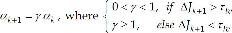
where ΔJk+1 ≡ Jk+1 - J k . This algorithm not only provides fast convergence properties but also reduces the unnecessary repeated circular motion of the UAV which results from a searching mode to the optimal location.
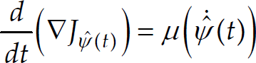
Note that the rate of the estimate of the current heading angle
Objective Function
In this section, a communication propagation model is introduced as a cost function for the input to the gradient controller. The propagation model includes the variation of free-space propagation loss, antenna pattern loss, and the effect of UAV orientation on the signal-to-noise ratio in the communication link (Rappaport 2002). The formula is based on Friis transmission formula, which is one of most dominant pass loss features affecting wave propagation in the radio channel.
The path loss model computes the path loss in dB between the UAV and ground relay nodes. The model for the path loss formula is based on Friis transmission formula and is expressed by


where f is a frequency in MHz and d(t) is distance in km. The link budget model computes the received power, the signal-to-noise ratio (SNR) and link margin of the receiver. The equations for the link budget are given by

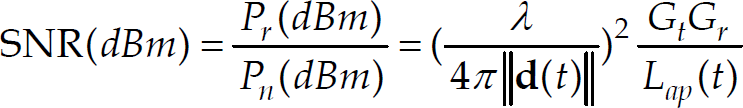
where P
r
(dBm) is the receiver power, P
t
(dBm) is the transmitter power (28dBm), R
sen
(dBm) is the receiver sensitivity (−74 dBm), G
t
(dB) is transmitter antenna gain (14 dB), G
r
(dB) is receiver antenna gain (2.2 dB),
The overall architecture of the decentralized cooperative control of distributed networked unmanned systems for meshed wireless communications networks is consisted of two main parts. The first phase is about a decentralized cooperative control of multiple aerial vehicles for optimal localizations of each vehicle in a meshed sensor networks. The second part is a formation flying control of a team of aerial robots to minimize bank angle effects for maximum communication throughputs between the aerial vehicles. Coordinated behavior in vehicle groups is locally controlled, and it is assumed that individuals respond to neighbors and local environment only and there is no need of group leadership and global information for decentralized control of networked multiple autonomous aerial systems.
In this paper, a decentralized cooperative control algorithm is developed for steering a team of multiple aerial vehicles to establish communication and sensing networks. Each aerial vehicle is controlled locally by an onboard controller which makes decisions based on the information communicated from the neighboring UAVs as to where to fly to maximize the most favorable communication signal strength. The onboard controller executes commands to steer an UAV in a decentralized and cooperative way until its relative value of the gradient estimate becomes zero.
In detail, the decentralized cooperative control capability necessary for building wireless communication networks using multiple UAVs is achieved by taking the following three modes, as shown in Fig. 2.

Flowchart for three modes for decentralized cooperative control architecture for UAVs
The purpose of the first mode is to increase the speed of convergence of each self-estimating gradient descent controller. Initially an artificial potential field is placed around the center point calculated based on the locations of remote nodes on ground or surface. The location of each UAV is controlled by its onboard adaptive gradient descent controller which executes commands by taking advantages of the received positioning information and signal-to-noise (SNR) values from neighboring aerial robotic vehicles, and the artificial and remote nodes.
In the second mode, at once each UAV reaches its pseudo optimal location which obtained by utilzing the artificial node for the gradient computation, the cost functions computed from the artificial node is replaced with an realtive cost functions whcih are constructed by using the information communicated neighboring UAVs and the remote nodes on ground or suraface in order to find an real optimal location of each UAV. In the third mode, a formation control is executed where the phase angle of a following UAV is synchronized with that of a leading UAV to maximize the communication throughput between aerial vehicles. This minimizes the variation of the SNR cost function between the UAVs to a nearly constant value. In the following, the detail of each mode is explained.
For distributed optimization of multiple aerial systems as relay nodes, the signal cost map is dynamic rather than static for the single UAV control case since the vehicles moving relative to each other generate dynamic nodes which have slow parameter-varying optimal cost functions. The self-estimating adaptive control of multiple unmanned aerial systems may exhibit slow convergence to the final optimal positions due to simultaneous optimization of multiple objective cost functions when the starting locations of the UAVs are far off from the optimal location. To alleviate the slow convergence, initial guidance law is designed for positioning the UAVs relatively close to the pseudo-optimal communication points. Two decentralized guidance techniques are introduced in, but in this paper a direct guidance law based on the concept of an artificial potential node is explored (Lee & Mark 2008).
As explained before, in this first guidance mode, an artificial potential node is introduced for each UAV along the line connecting neighboring two satic nodes or at the center among satic or slow-moving multiple nodes on ground or ocean. The proposed decentralized controller producing a control output based on the estimated gradient will allow each UAV to converge to the peak of its respective communication potential function by applying the adaptive gradient descent control technique explained. An advantage of using this method is that there is no parameter re-tuning in the gradient controller, which makes the UAVs converge to the specified point regardless of starting location.
For multiple communication nodes, the cost function is defined with interactions between the multi-nodes, and it is necessary to satisfy the constraint. Straight forward method to define a figure of merit of the cost function is to calculate an average value by adding all of each SNR
i
function with a proper weight value W
i

In the first mode, the adapative gradient descent controller takes the cost functions obatained from the communication throughputs between the ground nodes and aerial vehicles and the aritificial node and the aerial robots. For example, in Fig. 3, the cost functions as a figure of merit used as inputs for the onboard decentralized controller are given by


Concept of artificial node based initial guidance and control for fast convergence
where J
i,l
(u
i
|

3-D Plot of SNR map for UAV1 with links to ground node 1 and UAV 2
For fast initial convergence control in the decentralized control phase, an artificial potential based guidance is defined by

where
Now, question arises is how to determine the location of artificial potential node to be placed for initial guidance control. The ideal location of an artificial potential function is the center of the-line connecting neighboring ground antennas as shown in Fig. 4 where there are two ground nodes and one artificial node in the meshed networks.
The computational solution in the ideal location of the artificial node can be obtained by solving the line-of-sight SNR model. Figure 4 shows the example of the 3-D plot of the combined potential cost function constructed by using the links between the aerial communication link and a ground node as well as between two aerial vehicles with the architecture of the meshed networks.
The ideal cost plot shows the combined potential function along this path has a maximum when both SNR1 and SNR2 are equal, where SNR1 is the cost function obtained by the communication link between the UAV1 and the ground 1, SNR2 is the value from the communication link between the UAV2 and the ground node 2, and SNR12 is the value obtained from the links between the UAVs. The point where this maximum occurs is the predicted pseudo-optimal loitering location where an aritificial potential function should be placed for initial guidance of the aerial vehicles. In the second stage, once the UAVs have converged to the pseudo-artificial peaks, guidance will be switched to the second mode, decentralized gradient control, to guide the UAVs to the actual optimal loitering location based on the actual cost signal SNR12 which is the value obtained from the links between the UAVs. The decentralized controllers onboard the UAVs in the second mode take the control inputs of the SNR values obtained by the communication links between nodes and UAVs rather than accepting the SNR value obtained from the communication links between the UAV and artificial node, which is used for the initial guidance mode.
For decentralized cooperative control approach it is assumed that coordinated behavior in multiple vehicle groups is locally controlled, and individuals respond to the information communicated from neighbors and local environment only and there is no need of group leadership and global information for meshed communication networks.
After the first mode of the initial decentralized guidance is accomplished and each aerial vehicle finds its pseudo optimal location based on the communication betwee the artificial node and the aerial vehicles, the second mode is executed to steer each motion of the UAVs for optimal location by switching the communication from the artificial node to the communcation throughput between the neighboring aerial vehicles. In the second mode for decentralized cooperative control of multiple UAVs with general N nodes, it is necessary to define relative cost functions between the node and UAV (UAV to ground node and UAV to UAV) for inputs to each adaptive gradient descent controller. Suppose we have two communication nodes (i, j) with two UAVs (l,m) and they are all in a liner network such that a node can send data to next neighbor node. For decentralized cooperative control, a teams of vehicles cooperating to maximize each objective function allocated on each corresponding UAV is considered and the optimization problem can be expressed by for the ith UAV
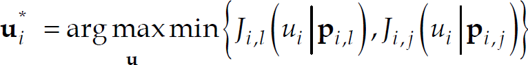
where J
i
(u
i
|

where J
i,l
is the cost function between the lth ground node (l = 1, 2…,m) and ith UAV, which is a function of the relative position vector

where κ
i
is the scale factor which controls the shape of the cost funciton, that is, how peak and smooth it is. The relative cost functions J
i
can be used directly as an input for the gradient descent controller for each ith vehicle. We just designed an decentralized control architecture with the adaptive gradeint controller applied. For a decentralized cooperative control approach it is necessary for each UAV to receive an information from neighboring UAVs to cooperate to maximize the same objective function, such as maximum communication throughtputs in relaying sensor networks. For cooperating capability, each onboard adaptive gradient descent controller executes its commands until the difference of the variations of the gradient estimate becomes zero, that is,

where ▽Ĵi,min(t) is the variation of the cost function of the ith UAV, and ▽Ĵj,min(t) is the variation of the cost function of the jth UAV.
After each UAV find its own optimal location, the decentralised cooperative control mode onboard UAVs will switch to a formation control mode where UAVs are flying in a coordinated way to reduce the effects of bank angle variation by synchronizing the phase angles of the UAVs as descributed in Figure 7. Once the optimal location for high bandwidth communication relay has been reached, the UAVs fly in a coordinated formation that minimizes the SNR oscillation of the communication links between the UAVs. The final loitering path will be a circular orbit centered at the optimal point with the UAVs flying in a synchronized phase angle pattern.
The goal of the phase-synchronized formation flying control is to maintain a constant or slow varying SRN power/magintude between the UAVs by reduce the SNR fluctuation due to the bank/roll angle desynchronized variations as shown in Figure 5. For analysis of the effects of the phase angle, four different synchronization patterns were simulated. Each case tested different synchronized phase spacing for orbits in the same direction. In this simulation, the follower aircraft synchronized its orbit in-phase, 90° ahead, 90° behind and 180° out of phase with the leading aircraft. The above simulation result shows that in-phase motion of an orbit in the same direction provides the greatest stability with minimal variations in SNR.

Concept of decentralized formation flying control to maximize communication throughputs between UAVs
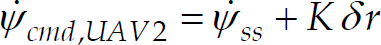
The above results motivated us to design a formation control law to mitigate the bank angle effects on the communication between the UAVs. The principle idea of a formation flying controller for multiple UAVs is based on a feedback phase angle control which makes a follower UAV to synchronize the phase angle of the leader UAV. The feedback control law is derived by using a method from a Kuramoto model (Lee 2009, Leonard) explaining a method for synchronizing harmonic oscillation. The proposed phase angle controller is expressed by

where K is a feedback gain,

The center of the current orbit location is calculated using the sensor data such as position, heading, and heading rate measurements by

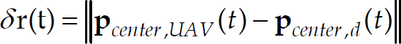
The distance between the current orbit center and the desired orbit center gives the offset error δr(t), which is used as the input for the second position shift controller by
where
Finally, the total feedback control law for the synchronized formation flying control is constructed by combining these two controllers to generate the desired heading command

where w1 and w2 are the weighting factors satisfying the constraint, ∑ i w i = 1.
The proposed controller synchronizes the follower networked aerial robot with the leader while maintaining an orbit over the optimal relay location. Figure 6 describs, for instance, the formation flying control which leads to the phase schronization between the leading aerial vehicle and the follower at the final synchronized time. On the other hand, Fig. 7 presents the flight trajectory of the follower aerial vehicle which is generated from the synchronization of the phase angles between the two aerial robots by using the phase feedback control technique.

Formation flying control with phase angle synchronization between the two aerial vehicles

Follower flight path with phase feedback control for formation flying
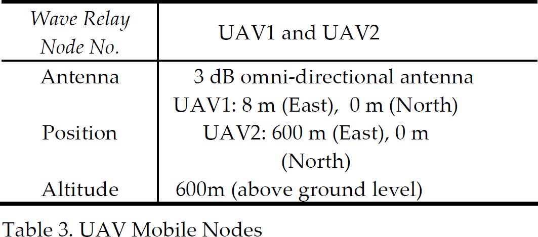
The “Hardware in Loop” (HIL) architecture represents a powerful and cheap method to test and tune control systems. The case of tuning devices involved in the aeronautical field is very critical, since experimental trials are performed with time-consuming test flights and unsatisfactory results could lead to dangerous situations. An HIL simulator cannot fully replace field experiments, but it is very useful, especially in the preliminary phases, to discover and solve various kinds of problems. Therefore, the major aim of an HIL platform regards improvement in development time, cost and risk reduction. Once the performance is suitable for the application, the same controller hardware can be directly connected to the real UAV. Hardware-in-the-loop (HIL) simulation studies for building a wireless meshed communicaiton networks were performed with two aerial robots relaying two ground-based wireless communication nodes (Jones, 2009). The primary objective of this simulation is to validate the performance of the proposed decentralized cooperative control technique for establishing stable high bandwidth communication links. The two ground nodes depicted in Fig. 8 acted as the command station and the survey vehicle while the UAVs functioned as the relay vehicles. The sensor node setup for the communication study is described in Table 1 and 2, and unmanned aerial vehicles are equipped with 3 dB omni-directional antenna shown in Table 3. The aerial vehicle is equipped with 2.2 dB omni-directional antenna (HG2402RD-RSF).

Relative Location of the GCS node and Remote Node [From Google Earth]
Ground Control Station (GCS) Node

Remote Node

UAV Mobile Nodes
The decentralized cooperative control technique consists of three phases to find optimal location of each UAV for high bandwidth communication links, and Figures 9 & 10 shows the demonstration of the performance of the proposed decentralized control technique. Fig. 9 shows the flight trajectory of the UAV during the test. Initially, the UAV was in a holding pattern orbiting north of the GCS node. When the control algorithm was activated, the UAV started to move in the direction of the steepest increase in the SNR value. When the UAV reached the region of peak SNR, a steady-state heading command was passed to make the UAV orbit around the optimal point. It was observed that the orbit around the optimal point was elongated and not a circular path. The circular lines shown in Fig. 9 are contour lines of constant SNR generated from the static SNR map in east-north coordinates for a stationary (non-dynamic) UAV with fixed altitude, heading, and bank angle. In the final state, after each UAV found its true optimal location, a synchronizing control algorithm is executed onboard each UAV in order to maximize the communication throughputs between the aerial vehicles with them flying in a formation with a same phasing angle. The purpose of the synchronized formation flying is to minimize the bank angle effects on the communication signal throughputs. A leader UAV executes orbit transfer to synchronize the phase angle of the other UAV by changing the orbiting radius. The communication between the multiple UAV has a maximum steady-state value, which guarantees the stable links between them by minimizing the bank angle effect.

Decentralized Control for Optimal UAV Positioning for Maximum Communication Links Between UAVs and Nodes
In Figure 10, SNR1 indicates the communication throughput between the GCS node and the UAV 1, SNR2 is the value between the remote node and the UAV2, and SNR12 implies the SNR value between the UAV1 to UAV2. The SNR values are converged to the same value, which means that the location of each UAV is optimal and its positioning at the converged state provide stable high bandwidth communication throughputs. It is seen that the UAV1 reaches its pseudo-optimal location from the decentralized initial guidance in less than 50 seconds, while the UAV2 finds its pseudo optimal location after about 100 second later. As can be seen that after about 180 second later the SNR12 is converged to a constant value, which indicates the formation flying with the phase angle schronization was achieved to minize the communication variation betwee the UAVs.
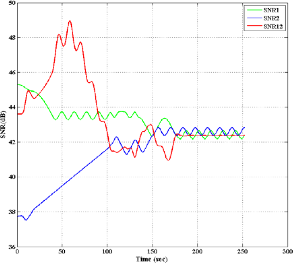
SNR variations between UAVs and UAVs to nodes as a function of time
In this paper, a decentralized cooperative control strategy for a team of aerial robotic vehicles was developed to establish wireless airborne communication networks between distributed heterogeneous vehicles. Each aerial robot serves as a flying mobile sensor performing a reconfigurable communication relay node which enabls communication networks with static or slow-moving nodes on gorund or ocean. For distributed optimal deployment of the aerial vehicles for communication networks, an adaptive hill-climbing type decentralized control algorithm is developed to seek out local extremum for optimal localization of the vehicles. The sensor networks estabilished by the decentralized cooperative control approach can adopt its configuraiton in response to signal strength as the function of the relative distance between the autonomous aerial robots and distributed sensor nodes in the sensed environment. Simulation studies showed the effectiveness of the proposed decentralized cooperative control technique for robust communication networksa coopedecentralized control technique. The proposed approach makes the communication and data relay mission more effective and robust compared to that of the conventional aerial platforms.