
Abstract
In the paper, a novel moving object detection (MOD) algorithm is developed and integrated with robot visual Simultaneous Localization and Mapping (vSLAM). The moving object is assumed to be a rigid body and its coordinate system in space is represented by a position vector and a rotation matrix. The MOD algorithm is composed of detection of image features, initialization of image features, and calculation of object coordinates. Experimentation is implemented on a small-size humanoid robot and the results show that the performance of the proposed algorithm is efficient for robot visual SLAM and moving object detection.
Introduction
In recent years, SLAM systems have been successfully implemented and validated by many researchers (Dissanayake, M.W.M.G. et al., 2001; Davison, A.J. et al., 2007; Montemerlo, M. & Thrun, S., 2007; Wang, C.C., 2007). Especially, the MonoSLAM developed by Davison, A.J. et al. (2007) provides a real-time algorithm which can locates the 3D trajectory of a monocular camera and maps the beacons in the environments, simultaneously. Nevertheless, the research in this paper aims at providing a novel moving object detection (MOD) algorithm for a class of visual SLAM systems, as well as implementing the visual SLAM with MOD on a small-size humanoid robot system.
MonoSLAM (Davison, A.J. et al., 2007) utilizes an extended Kalman filter (EKF) to update the estimation of the robot state as well as the map of beacons in the environments, recursively. We extend the method of state estimation to detection of a moving object. The basic concept is to collect the nearby image features together to form a prospective object in the environments. In the paper, the object is assumed to be a rigid body and its coordinate system in space is represented by a position vector and a rotation matrix. We present a procedure to form the body-fixed coordinate by choosing three arbitrary and non-collinear image features on the object, and then determine the rotational angles of the object in terms of the roll-yaw-pitch coordinate system.
The developed visual SLAM with MOD is verified through experiments on a small-size humanoid robot. The experimental results show that the performance of the proposed algorithm is efficient for supporting the small-size humanoid robot simultaneously navigating and detecting moving objects in the environments.
The contributions in this paper are two-fold. First, we develop a novel moving object detection algorithm and integrate with MonoSLAM. Second, the SLAM with MOD is implemented on a small-size humanoid robot system.
EKF-based SLAM
Based on the EKF estimation method, Davison, A.J. et al. (2007) proposed the MonoSLAM which can proceed to estimate the state of the free-moving camera with a monocular vision and construct the environmental map, simultaneously. The free-moving camera is presumed to be at constant velocity, and the acceleration is caused by an impulse noise from the external force. Therefore, the velocity noise of the camera is defined as:

where k is the time step; a and α are linear and angular acceleration of the camera, respectively; Δt is the sampling time interval; w
v
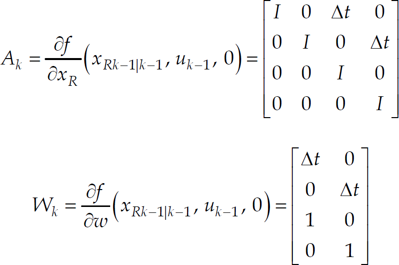
and wω are linear and angular velocity noise caused by acceleration, respectively. Using the EKF method to estimate the state of the system, and the vector of the state is chosen as
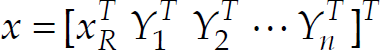

The Jacobian matrices A
k
and W
k
for calculating the covariance matrix are given as
Sensor Model
MonoSLAM uses a monocular vision as the only sensing device, and the measurement vector is given as


I
ix
and I
iy
represent the measured pixel coordinates of the i
th
image feature with Gauss noise v
ix
and v
iy
; I
ix_true
and I
iy_true
are the real pixel coordinates. The perspective projection method (Hutchinson, S. et al., 1996) is employed in this research to model the transformation from 2D image plane to 3D space coordinates,

where f
c
is the focal length of the camera denoting the distance from camera center to image plane; (u0, v0) is the offset pixel vector from the hardware image plane to pixel image plane; k
u
and k
v
are the image pixel correctional parameters. Assuming that there is no distortion phenomenon on the image plane and we make k
u
and k
v
as 1;

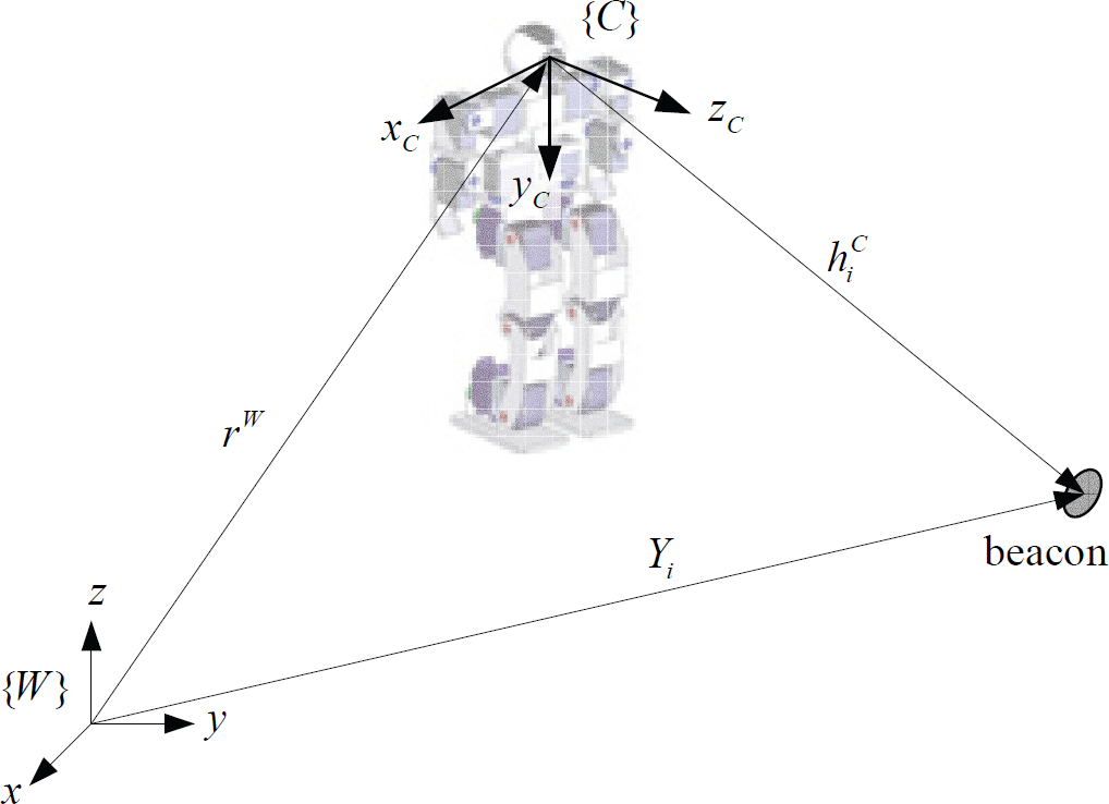
The camera frame and the world frame.
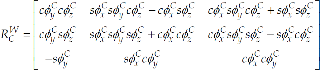
where cφ
C
= cosφ
C
and sφ
C
= sinφ
C
. We can utilize Eqn. (2) to calculate the ray vector of an image feature in the camera frame. The vectors


Substituting the ray vectors, Eqns. (3)–(5), into Eqn. (1), we can get the sensor model in terms of coordinates of the image feature in the image plane.
During navigating in the environments, the robot locates its global coordinate by consulting the positions of a group of fixed features or beacons. These features are abstracted from the captured image and an initialization process is applied to determine the 3D coordinates of these image features. In the paper, the image feature initialization algorithm proposed by Wang, Y.T. et al. (2009) is employed to initialize the features for SLAM and moving object detection. The procedures of the algorithm include detection of image features, selection of “good features” (Shi, J. & Tomasi, C., 1994), calculation of image depths, and update of feature locations.
In the feature initialization algorithm (Wang, Y.T. et al., 2009), the features are extracted from the image by using the method of Speeded Up Robust Features (SURF) (Bay, H. et al., 2008). SURF is a scale-invariant method for detection of image features. It detects region features from an image and obtains the location and the descriptor vector of each interest point. The basic concept of a scale-invariant method is to detect image features by investigating the determinant of Hessian matrix H (Lindeberg, T., 1998). Bay, H. et al. (2008) utilize a box filter to process on the image instead of calculating the Hessian matrix, and then the determinant of Hessian matrix is approximated by

where D ij are the images filtered by the corresponding box filters; w is a weight constant. The interest points or features are extracted by examining the extreme value of determinant of Hessian matrix. Furthermore, the unique properties of the extracted features are described by using a 64 dimensional descriptor vector.
The extracted features from two successive images can be matched by checking the Euclidean distance d between the corresponding descriptor vectors, and using the nearest neighbor ratio matching strategy (Lowe, D.G., 2004). Therefore, the region features of two images can be tracked efficiently. The matching ratio r is defined as the ratio of the smallest distance d1st to the second smallest distance d2nd. If the ratio r closes to 0.7, we say that these two features are matched.
The depths of image features are calculated using two successive images, as shown in Fig. 2. Assume that there are m image features with 3D position vectors, Y i , which can be described as Eqn. (2). After determining a good feature i, the xyz coordinate of the feature Y i is obtained by calculating the image depth of the feature in two successive images (Wang, Y.T. et al., 2009).

Image depth obtained by two successive images
The moving object can also be detected by investigating the image features on the object, as shown in Fig. 3. For reasons of simplicity, we make three suppositions: first, the image features of a moving object are known; so, it is not necessary to carry on the procedure of object recognition; second, the object is a rigid body and not deformable; therefore, the position vector and rotation matrix of a rigid body can be used to describe the object movement; finally, the object moves slowly or stops sometimes, and then the images taken by the camera may be regarded as at the same position.

A group of fixed beacons and a moving object in the initial scene t=0
Before the process of object detection, the body-fixed coordinate of the object is constructed and the feature database is established by using the image feature detection and tracing method. The description and position vectors of the image features on the object are stored in the established database. We setup the body-fixed coordinate system on the object by using the procedure defined as follows.
Procedure 1
Body-fixed coordinate setting
Choose three image features A, B, and C from the initialized feature set. The origin of the coordinate system is set at A, as shown in Figure 3. The vector
The algorithm for moving object detection (MOD) is summarized as the following steps:
At the current scene, choose three image features that have the largest values of the determinant, called F
j
, Fj+1 and Fj+2. And then calculate the description vector of the image feature and its 3D position in world coordinate. Utilize By using the description vectors of image features F
j
, Fj+1 and Fj+2, we can retrieve their correspondences, features M
j
, Mj+1 and Mj+2 from the feature database. Note that M
j
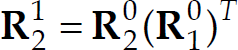
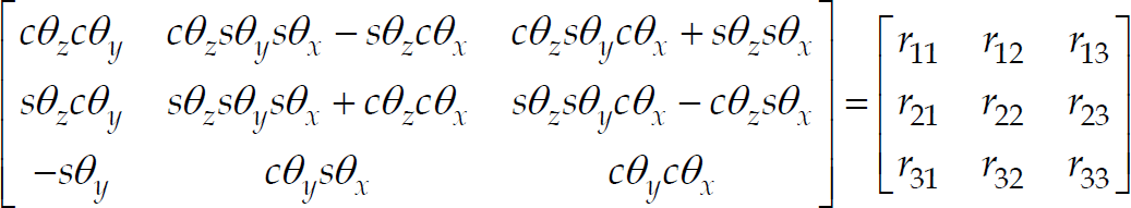
, Mj+1 and Mj+2 are the features extracted from the initial scene. Using Utilize the rotation matrices Note that, the rotation matrix The RPY angles of the rotation matrix By investigating the relative position between points M
j
, Mj+1, Mj+2 and points A, B, C, we can determine the image correspondence A′, B′ and C′ at the current scene. In the paper, the translational vector


The same group of fixed beacons and a moving object in the current scene t=k
Humanoid Robot
A small-size humanoid robot is designed and fabricated for demonstration, which is equipped with a Microsoft Windows-based industrial PC. The appearance of the designed robot is depicted in Fig. 5 (right). The control system comprises three subsystems, including a vision sensor system, a PC-based control system, and a motor drive system. Each subsystem is able to work independently and also in coordination with each other. The camera system is the only sensor to provide the robot position information in the environments. In this research, we develop the control system by utilizing a Windows-based industrial PC, Wafer-LUKE533, provided by a local vendor. The fabricated robot is 51cm in height and 3kg in weight, including two 12V/2.5AH Li batteries. One battery provides the power for 18 servo motors and the other provides for the controller. The motor drive system is composed of a SSC-32 circuit board and is responsible for driving all the servo motors.

Pre-stored image features (left); Robot stands in front of the pre-stored image features (right).
First experimental work is the startup procedure of the system. The EKF-based SLAM must have a startup procedure to determine a reasonable scale of the map. In the startup procedure, several features with known 3D positions and description vectors, as shown in Fig. 5 (left), are stored in the database. The robot stands in front of the image features. By using the SURF method, the image features are detected from the captured image and the 3D positions are retrieved from the pre-stored database. The initial camera state is assumed to be located at an arbitrary position, for example, [0, 0, 0] T . However, the real camera state locates at [3, −70, 2.7] T . Three startup experiments are tested and the results are depicted in Figs. 6(a) and (b). These figures denote the estimated camera states plotted in x-y and x-z plane, respectively. We can see from the plots, the EKF estimations of the camera state begins from the arbitrary initial position [0, 0, 0] T and converge to [0, −55.8, 3.7] T . The reasons the estimated states do not converge to the real positions, indicated as a triangular mark in both plots, are the un-calibrated and distortion problems of the low-cost camera.
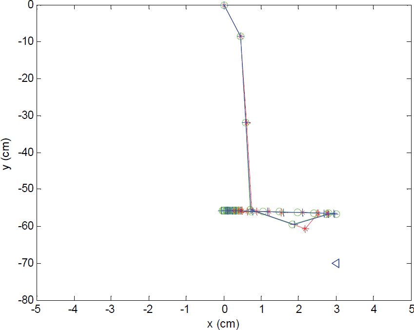
Experiments of the system startup procedure. The plot of the camera state in x-y plane

Experiments of the system startup procedure. The plot of the camera state in x-z plane
The EKF-based visual SLAM is also implemented on the small-size humanoid robot. We integrate the procedures including the image feature detection and tracking method, feature initialization, system startup procedure, and EKF-based state estimation. And then perform the robot self-localization and mapping procedures simult-aneously. In this experiment, the robot moves from the left- to right-side of the field, as shown in Fig. 7 and the estimate state and image features are depicted as a 3D map shown in Fig. 8. In the plot, the dots indicate the landmarks obtained from the initialized image features and the asterisks represent the state of the camera equipped on the robot.

Humanoid robot moves from left- to right-side of the field. Meanwhile, the EKF-based visual SLAM is performed
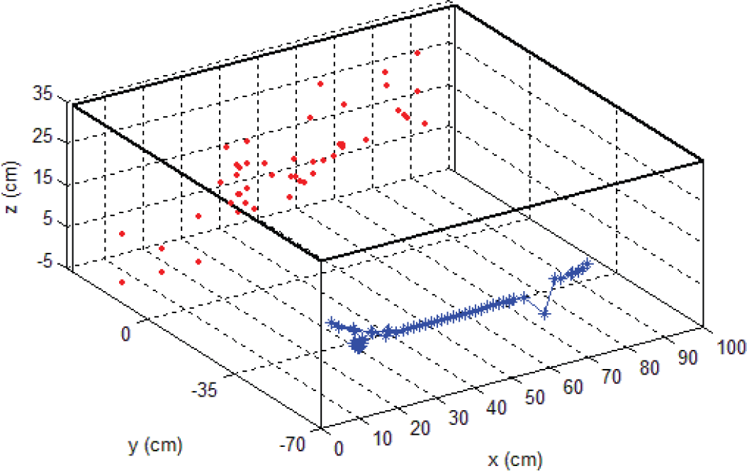
Three-dimensional plot of the estimate state and image features.
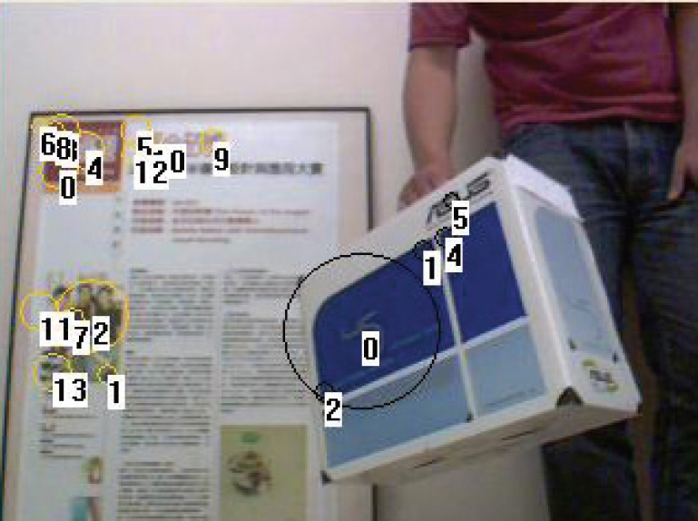
The experimental set-up of moving object detection is depicted in Fig. 9. The humanoid robot implements robot SLAM and moving object detection in a corner of the laboratory. Four different locations of the moving object are tested and shown in Fig. 10. By using the proposed initialization algorithm, fixed features (yellow circles) in the environments are selected as beacons for robot SLAM, while the moving features (black circles) are classified as the image features on the moving object. The displacement and orientation of the detected object are listed in Table 1. In the table, the object displacement xyz indicates the translational displacement from the origin of the world coordinate (set on the camera) to the origin of the coordinate on the box, which is located on top-right corner of the box. The object orientation represents the yaw-pitch-roll angles of the box with respect to world coordinate. The results show that the proposed method determines the position and orientation of a moving rigid object effectively.

Experimental set-up

Moving object detection: Location B0
Moving object detection: Location B1

Moving object detection: Location B2

Moving object detection: Location B3
Displacement and orientation of the moving object

In this research, we developed an algorithm of moving object detection (MOD) and integrated it into the MonoSLAM. The moving object is detected by extracting the image features on the rigid body. Three arbitrary features are chosen to form a coordinate systm representing the moving object at current scene. The coordinate system of the initial scene is obtained by matching the extracted image feature with that in the database. The displacement and orientation of the moving object is determined by solving the inverse problem of the rotation matrix from initial scene to current scene.
The tasks of SLAM with MOD are implemented on a PC-based controller for a small-size humanoid robot. The contribution of this research is in two aspects: firstly, a novel algorithm for moving object detection is developed for the EKF-based SLAM by using SURF, a scale-invariant image feature extraction method. Secondly, the SLAM with MOD is implemented on a small-size humanoid robot system. Experimental works are performed in this paper and the results show that the SLAM with the proposed moving object detection algorithm has the capability to support the humanoid robot simultaneously navigating and detecting moving objects in the environments.
Up to now, the developed detector can determine rigid moving objects. In the future, we will extend the method to detecting multiple objects with different moving velocities, or non-rigid moving objects like human body with articulated arms and legs.
Footnotes
6.
This work was supported in part by the National Science Council in Taiwan under grant no. NSC98-2221-E-032-012 to Y.T. Wang.