
Abstract
Rudder based roll control of a small-sized robotic boat is a key technique for the devices on board to achieve good performance. This paper introduces a host-based robotic boat capable of performing basic movement operations. The course keeping and roll reduction are studied via rudder based method in simulations and sea trials. The boat dynamic model is built with the combination of mathematical analysis and system identification technique. A mixed sensitivity H∞ control method design is selected since yaw and roll motion are posed in different frequency domains. Computer simulations and experiments carried out show that successful results are achieved.
1. Introduction
With the recent advances in communication and control devices, autonomous vehicles such as UAV (Unmanned Aerial Vehicle) (Yu,Z., Nonami, K., Shin, J. & Celestino, D., 2007), UGV (Unmanned Ground Vehicle), UUV (Unmanned Underwater Vehicle) and USV (Unmanned Surface Vehicle)have been receiving attention for various applications and missions in recent years. For example, USVs are used in the field in explorations of water depth, pollutant tracking and environmental hydrographic surveys in rivers, reservoirs, inland waterways and coastal waters. Particularly, applications in narrow lakes or coastal areas dangerous to manned vessels are more feasible for USVs. Among the USVs, the robotic boat (‘the boat’ hereafter) is an effective and safe vehicle to carry out various marine missions. To the authors' best knowledge, the boat we investigated is the smallest one among those reported in the literature. The low speed and small dimensions of the boat make it prone to environmental disturbances, such as wind and waves. These problems make this kind of research challenging. For USVs in the applications mentioned above, roll stabilization is of critical importance to ensure good performance for on-board equipment such as ultrasonic sensors and video sensors. There are several approaches that can be used to reduce the roll motion, such as bilge keels, anti-rolling tanks, fin stabilizers and rudder roll stabilizers (RRSs). Since the rudder based approach requires no additional equipment and is thus a relatively inexpensive solution, it has been analyzed by numerous studies with different control schemes like LQR(Van Amerongen, J., van der Klugt, P. & van Nauta Lemke, H., 1990), H∞ (Stoustrup, J., Niemann, H. & Blanke, M., 1994), SMC (Lauvdal, T. & Fossen, T. I., 1997), and IMC (Tzeng, C., Wu, C. & Chu, Y., 2001). All these methods, in some way, are mathematical models for which the parameters are derived from the Planar Motion Mechanism (PMM) and the results based on these models are rendered by computer simulations. Experimental studies including actual sea trials are very rare, especially for small-sized boats. In this paper, we introduce a design of radio-controlled boat, the controller of which is calculated on the ground station, and the rudder based roll control approach is validated by sea trials.
The paper is organized as follows: In Section 2, the mathematical model coupling yaw roll and sway is described. In Section 3, the robotic boat platform including hardware integration and control configuration is presented. The controller based mixed sensitivity H∞ is shown in Section 4, and the experimental results are given in Section 5. In Section 6, Conclusion is described.
2. The Robotic Model
The model was derived from basic principle of physics that borrowed from the theory of rigid body dynamics. System identification requires a combination of theoretical and experimental methods to determine the most important hydrodynamic coefficients. Model describing the interaction between roll, sway and yaw with a given service speed U can be given in a 3-degree-of-freedom system. The coordinate system of the boat is shown in Fig.1.

Coordinate system of the boat
The motion of the boat is considered as a translation motion (position) in sway directions; and as a rotation motion (orientation) about x and z axes: yaw and roll. Using this set-up, the equations are easily developed using a global coordinate frame {I} and a body fixed coordinate frame {B} that moves with the boat. The following notations are needed.
η = [y φ ψ] T -position-orientation vector of {B} expressed in {I}.
v = [v p r] T - linear-angular velocity vector of {B} relative to {I}, expressed in {B}
Γ = [Y K N] T -force and moments in sway, roll and yaw direction respectively.
The dynamics equations for the model can be obtained from Newton-Euler laws following the classical approach descirbed in[Fossen, T. I., 1995].


Where C RB denotes the matrix of Coriolis and Centripetal terms. For our boat the model can be written in a state-space form as:


where

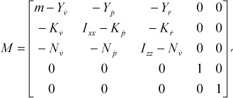
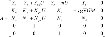

C is 5-by-5 identity matrix. v sway velocity, p roll rate, r yaw rate, φ roll, ψ yaw, and definition of the other parameters are tabulated in Table 1.
Definition of symbols
3. The Boat System for Investigation
The overview of the system design is demonstrated in Fig. 2. The control architecture is a host-based approach. Wireless LAN (WLAN) is in charge of interaction between the boat and the ground station. All control decisions are made at the ground station. Sensor data originates from the boat side, and the control commands are generated by running the control algorithm at the host. The command is sent to the boat via the WLAN. The host is a Pentium III laptop running Windows XP with a 256 MB RAM. With this configuration, we can modify and test our control algorithm easily. There is no need to download the program to the processor on boat side whenever any program changes take place, as in the case where the controller is located on the boat. It is useful for fast prototype phase in the development. The boat control system comprises three essential components: the boat, sensors and a ground station.

Overview of the boat control system
3.1. The boat represention
The robotic boat investigated in this study is one meter long and 0.25 meter across (beam) as shown in Fig. 1. The draft is 0.135 meter. The maximum forward speed is about 1.2 m/s. A rudder with pintle is hung on the stern, and is actuated by a servo motor with an operating speed of 0.1 sec/60°, and the rudder aspect ratio is 2.1. A four-blade propeller is configured in the front of the rudder, which is a left-handed propeller that turns counterclockwise to produce forward thrust and is driven by two DC motors. The power source comes from two Ni-Mn batteries and the endurance under the cruising speed is about 60 minutes.
3.2. Sensors package
The sensors used in the system include a rate gyro, a tilt-compensated 3-axis compass module that can measure rotational angles, and a GPS for measuring boat speed. The gyro sensor used in this work was home-made, whereas commercial rate gyros such as ADXRS150 from Analog Devices, Inc. may also be suitable. The hardware of sensor module (except GPS) is shown in Fig 3. The unit in the blue dashed rectangle is the gyro, the compass module is shown in the yellow rectangle, and the two ATM processors are shown in the red rectangle.

The hardware integration of sensors.
3.3. The ground station
The ground station consists of a ground computer and two wireless modems. Sail data is stored and displayed simultaneously. Calculated control commands (rudder deflection angle) by the ground computer are converted to pulse generator we developed independently and sent to the boat. The sensors data also can down link for the controller inputs use.
4. Controller Design
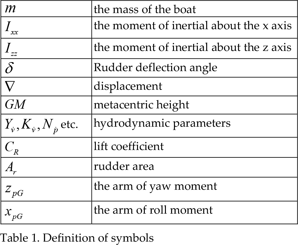
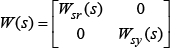
The combined yaw and roll controller we designed is an SIMO one. The controller design is based on mixed sensitivity approach. Mixed sensitivity is the name given to transfer function shaping problems in which the sensitivity function S is shaped along with one or more other closed-loop transfer functions such as K(s)S(s) or complementary sensitivity function T, etc. It is suitable for the case of boat control. It is desirable to maintain the boat along the reference line under the time-delay and model uncertainty. A schematic representation of mixed sensitivity H∞ is shown in Fig.4. For the design of the robust controller, the design specifications for the yaw and roll are given by two disturbance weighting functions W sy and W sr , where are placed at he external output. Also the weighting function W t described as control input is placed at the external input. The variables such as Z1, Z2, Z3 are the controlled outputs, to be specific, Z1 and Z2 is the penality on distanbance reponse, and Z3 is the penality on control input.
H∞ control with mixed sensitivity
The model uncertainty and environmental disturbance are treated in output multiplicative form. The design problem is to find the controller K for which

where
The K can be solved efficiently using Matlab LMI control toolbox. Simulation results of the yaw angle and roll angle are shown in Figs. 5 and 6.

Simulation result of yaw motion

Simulation result of roll motion
5. Experimental Results
In our sea trial the test scheme is illustrated in Fig. 7. We compare the only yaw control with yaw and roll combined control. Due to the range limit of wireless LAN communication, we could not perform long distance tests. The designed controllers were tested in the sea with 0.5 meter waves with the boat running at a maximum speed of about 1.2 m/s. In Fig. 8 two roll sensor plots are shown without and with roll control, respectively. The roll angles without and with roll control are shown in Fig. 9.

Running in beam sea

Yaw control results
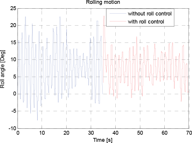
Roll reduction results
The criterion for roll reduction can expressed as following (Perez, T., Tzeng, C.Y., Goodwin, G.2000):


where Yaw and Yaw' are the RMS errors without and with roll control respectively. The same definition in Roll' and Roll angle. It was found that using rudder based roll control approach can lead to 32% roll motion reduction though yaw performance was reduced by 13.2%.
6. Conclusions and Future Works
In this paper, we have developed a rudder based roll control system for the robotic boat. We designed a mixed sensitivity H∞ controller to control yaw and roll attitude. Simulation and experimental results show that the robotic boat can be implemented by rudder based roll approach. The simplified dynamics model is proven to be valid in yaw and roll control. It implies an attractive possibility for future application of robotic boats. Because the wave model is not considered, there are some difference in the results of the simulation and experiment. In then next step, we will take the wave model into account, which will make the penalty bound specification more explicit and the controller more efficient. In an attempt to get better roll reduction result, a boat with high speed is necessary for increasing fluid force acted on the rudder surface, so the rudder will have stronger controllability. The topics of our further research include development of a boat with embedded control and obstacle avoidance based video.