
Abstract
This paper presents for the first time the use of the Leap Motion device to control an anthropomorphic gripper with five fingers. First, a description of the Leap Motion device is presented, highlighting its main functional characteristics, followed by testing of its use for capturing the movements of a human hand's fingers in different configurations. Next, the HandCommander soft module and the Interface Controller application are described. The HandCommander is a software module created to facilitate interaction between a human hand and the GraspIT virtual environment, and the Interface Controller application is required to send motion data to the virtual environment and to test the communication protocol. For the test, a prototype of an anthropomorphic gripper with five fingers was made, including a proper hardware system of command and control, which is briefly presented in this paper. Following the creation of the prototype, the command system performance test was conducted under real conditions, evaluating the recognition efficiency of the objects to be gripped and the efficiency of the command and control strategies for the gripping process. The gripping test is exemplified by the gripping of an object, such as a screw spanner. It was found that the command system, both in terms of capturing human hand gestures with the Leap Motion device and effective object gripping, is operational. Suggestive figures are presented as examples.
1. Introduction
Lately, in direct connection with applications in robotics and informatics, complex research on motion capture of the human body has been conducted, especially in regard to human hand motion. Motion capture of the human hand is very complex because each finger, and even each phalanx, has distinct and independent movements. Over time, various solutions to this problem have been identified, requiring, in addition to adequate software for data processing, a suitable sensor model to record finger configurations. A live question in the field at this time is how to increase the accuracy of such sensors. The solutions that have been proposed can be classified as either invasive or noninvasive approaches. Data gloves (e.g., the Cyber Glove) and similar devices that incorporate bending sensors belong to the first category. Noninvasive solutions are based on image capture techniques. Initially, invasive techniques were more accurate than their noninvasive counterparts, but over time this gap has narrowed, such that recent iterations of the noninvasive solution have become, in some respects, even superior to the invasive versions. Initially, noninvasive solutions relied on an RGB camera to capture the signals of markers located on the target body parts (in this case, human fingers). Such configurations can be seen in [1]. Other developed solutions relied on following the contour of the target body part [2], on following edge zones [3] or on artificial intelligence [4]. All such solutions have returned quite good results, but these achievements are modest when viewed from the perspective of user needs. Significant progress was only recently achieved with the introduction of the Microsoft Kinect sensor [5] and most particularly the Leap Motion sensor [6]. These sensors provide sufficient accuracy, leading to similar outcomes as invasive techniques when used in the same field. Thus, based on the results obtained using these types of sensors [6,7] it has been demonstrated that the Kinect sensor has gradually become recognized as a useful means by which to capture depth data, and could even become an alternative to invasive techniques, such as data gloves. The Kinect sensor still possesses a limitation in terms of the accuracy of the captured data depending on the distance between the sensor and its object, and it has been demonstrated in [6] that the use of the Kinect sensor does not lead to satisfactory results when capturing configurations of human fingers, specifically. To overcome this weakness, the use of a Leap Motion sensor [6], a relatively new solution launched in 2012, has proved promising. A study that convincingly shows that the data obtained using a Leap Motion sensor are comparable to those obtained with a data glove is presented in [8], demonstrating that this sensor can be successfully used to capture configurations of human fingers and transmit such data into a virtual environment for identical configuration of a virtual hand. As a follow-up to reference [8], this paper presents a comprehensive solution for controlling a real anthropomorphic gripper using data captured by a Leap Motion sensor type, detailing the hardware and software components used.
2. The Leap Motion device
2.1. The leap motion device - operational characteristics
Reference [8] presents in detail the operational characteristics of the Leap Motion device. It should first be noted that this device, when capturing hand movement, implements a new way of detecting the human hand and a new means of gesture recognition. Distinguishing it from the Kinect sensor, the producers of Leap Motion claim that this sensor possesses sub-millimetre accuracy. In contrast to devices currently existing in the market, the Leap Motion sensor is under discussion for potential use in interaction applications in virtual environments [9]. We here further outline these features, with greater emphasis than that presented in [8] regarding the usefulness of the Leap Motion device in capturing the configurations of human fingers.
Moreover, the Leap Motion device provides a new method that is cost efficient, fast and precise in its capture and digitization of human finger movements.
The main purpose for which this device was created is the detection and recognition of human hand gestures and detection of the hand's position. These functions are then used in software applications in various fields. As the producers affirm, the sensor's detection of human hand gestures is accurate to approximately 0.01 mm (100 times more accurate than the Microsoft Kinect sensor). The Leap Motion device consists of three infrared transmitters and two depth data capture cameras [8]. From a functional perspective, the Leap Motion device can be assigned to the category of devices using active triangulation. The position delivered is relative to the Leap Motion device centre, which is located in the centre of the second infrared transmitter [8].
2.2. Using the leap motion sensor to detect the human hand and to capture complex gestures
Compared to the Microsoft Kinect sensor, which, due to a distance of less than one metre between the sensor and the user, is unstable in terms of gesture recognition, the new Leap Motion sensor is much more efficient owing to its new hardware system.
Information about a user's hand, fingers and gestures can be recognized as long as the hand is between 25 mm and 500 mm above the centre of the sensor [8].
By contrast to the sensor accuracy of the Microsoft Kinect, Leap Motion's sensor precision is of the sub-millimetre order, as specified in the Leap Motion documentation - more precisely, 0.01 mm [10].
With the programming interface that equips the Leap Motion device, the user has access to data about the human hand direction, speed and rotation.
The Leap Motion device has an attached programming interface called Leap Motion SDK. It allows programmatic access to depth data and was designed so as to allow for use via either high or medium level languages (Objective-C, C ++, Java).
From a functional perspective, the Leap Motion sensor analyses a data stream, which is divided by SDK in directly time-dependent frames, allowing for calculation of gestures or the speed with which a human hand moves above the sensor.
One great advantage of the Leap Motion sensor as compared to its predecessors is that it can distinguish each finger individually. The identification algorithm attaches to each finger, gesture and hand a unique identifier, making it easy for each entity to be tracked throughout the motion flow. If, at some point, a detected object to which a unique identifier is attached exits the frame, another unique identifier will be attached upon its re-entry of the frame.
Positional data are provided for each object, with sub-millimetre accuracy, on each axis of coordinates X, Y and Z from the centre of the device [8].
Spatial data captured from the real environment are translated using the SDK to different environments, which are related by the following classes: Screen, InteractionBox, Touchzone.
The Screen class describes the user's monitor position and orientation relative to the Leap Motion coordinate system. This structure includes the lower left corner of the screen, direction vectors for the vertical axes of the screen and the normal vectors of the screen. The Screen class provides several intersection methods that calculate how the hand direction intersects the screen. The intersection points are defined using normalized screen coordinates [8]. The origin point of the screen is characterized as the 0.0 point located in the lower left corner of the screen, with the top right corner normalized to 1.1. This means that the intersection points x and y must be between the values 0 and 1 (the z coordinate value is always zero).
The InteractionBox class is a rectangular area above the Leap Motion device which is visible in full to the latter [8]. The Leap Motion coordinate system can be mapped to a point relative to the volume represented by the InteractionBox class. The value is scaled so that the volume of the parallelepiped represented by the InteractionBox class is treated as a single cube, with the origin in the lower left corner farthest from the user.
The TouchZone class can be used with a pointable object, which may be a finger or a sharp object. The TouchZone class is used to implement an imitation of a surface sensitive to touch, without the need for an actual physical surface. The touch surface is divided into two areas, the float area and the actual touch area, which are identified with a touch distance between −1 and 1.
The system initialization to detect human hand gestures is as shown in the figures below. When the application uses the Leap Motion sensor, the onConnect method is selected, using as its parameter a mapping class of the Leap Motion sensor, namely the Controller class.
Using the onConnect method, the human hand is detected, each finger having a unique identifier attached. The length of the hand (in mm) and the speed (in mm / s) of the hand are detected.
For the configuration of the Leap Motion sensor parameters, the Config class is employed. This class permits access to the physical configuration system for the Leap Motion device. Initialization is performed by executing the following instructions:
ctlr.Config.SetFloat(“Gesture.Swipe.MinLength”, 5);
ctlr.Config.SetFloat(“Gesture.Swipe.MinVelocity”, 100).
The Save method is selected to save changes in the configuration of the Leap Motion device parameters.
In order to allow for human hand tracking and gesture recognition, the EnableGesture method should be selected with the following parameter:
ctlr.EnableGesture(Gesture.GestureType.TYPESWIPE).
Following initialization, it is possible to work with every frame individually. When a new frame is captured, the OnFrame method is selected. It captures and transmits data to the mechanism implemented to recognize human hand gestures.
For each frame captured, hand existence it verified using the Empty property of the Hand class. If this property is set to the “false” value, the first value of the vector corresponding to detected hands is read and a vector that will contain structures initialized for fingers is created using the following instructions:
Hand firstHand = currentFrame.Hands[0];
FingerList fingers = firstHand.Fingers.
For work with a human hand in a frame in which it was detected, the Hand class is used. It provides information regarding the position, features and movements performed by the hand, along with a list containing each finger associated with the hand. The Hand class provides attributes that permit access to the physical characteristics of the hand that is detected [11]. These include palm position, for which the centre of the palm is measured in millimetres from the point of origin of the Leap Motion device, and palm speed, which is the speed of the palm between two consecutive frames. The palm normal is a vector, perpendicular to the plane formed by the palm of the hand. The vector of points coming out of the palm include the following: direction - a vector oriented to the fingers originating in the centre of the palm; the centre of the sphere - the centre of a sphere that intersects the curvature of the hand; the radius of the sphere - the radius of the sphere that intersects the curvature of the hand.
Comparing data that provide access to the physical characteristics of the hand, the Leap Motion SDK provides attributes that enable access to the hand movement detected between two different frames. The Leap Motion sensor analyses the movement of the hand and its fingers and reports it as translation, rotation or scaling using reference [11]. The elements used are, first, the axis of rotation – a direction vector that stores the rotation axis. Then, the rotation angle – the angle clockwise around the axis of rotation. The rotation matrix is a transformation matrix that expresses rotation. The scaling factor is a factor expressing expansion and contraction. Translation is a vector, which expresses linear movement.
In addition, using the Leap Motion SDK, we can detect fingers with their properties: length, visible length, width, direction and tip speed. The unit direction of the vector point is in the same direction as the object. The tip position is expressed in millimetres from the origin of the Leap Motion device.
2.3. Testing the system and analysis of results
To use and test the system [12] we aimed, in the first instance, to achieve recognition of different human hand gestures. Then, using these gestures, we tested the gripping of different objects in the virtual environment.
To recognize the hand, various data sequences captured by the Leap Motion device were analysed. These sequences were captured in different lighting conditions (daylight and artificial light) and different positions [8].
Empirically, it was noted that gesture recognition is not dependent on lighting conditions when using the Leap Motion device.
3. General Command Solution
3.1. The handcommander module
To evaluate and transmit human hand gestures in the virtual environment, we created a module for interaction with the virtual environment. This system is divided into four components: hardware, frames processor, gestures detector and HandCommander components. The hardware component represents the Leap Motion sensor and is also responsible for supplying the raw data. Once the data are available, the Leap Motion device sends the data to the frames processor for further evaluation. The frames processor consists of the Leap Motion software module and the gestures detector. The Leap Motion software module processes the input from the sensor and calculates the information regarding the current status of the human hand. These data are sent to the gestures detection module, whose main function is to detect gestures, such as gestures of selection, movement and object release. When a gesture is detected, the gestures detection module notifies the HandCommander functional simulation component to send data for gesture performance in the virtual environment. The component architecture is divided into the Helpers module, which contains Helper classes that are used by other components. The HandProcessor is the frames processor that detects hand gestures. The HandSIM interface is the communication interface with the virtual reality simulator, which is represented by the HandCommander component. The HandProcessor component examines each frame containing a human hand to detect the fingers’ conditions. The results of this processing are used to populate data in a Hand type structure.
The Helpers module is a library that contains Helper classes and data structures that are used by the other components to analyse gestures and to recreate gestures in the virtual environment (see Figure 1). One of the most important classes of this module is the Hand class.
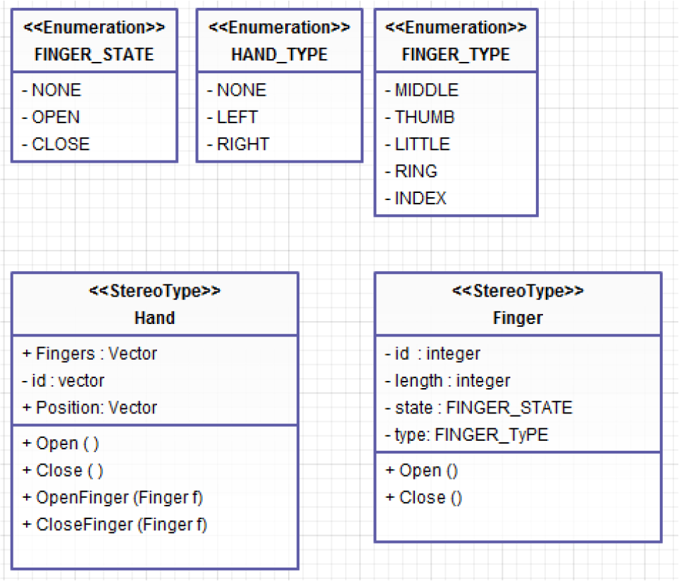
Component classes of the Helpers module
The Hand class includes data regarding the hand position and the status of each finger. The Hand class transmits to the gestures processor a unique identifier and another identifier indicating whether the hand is left or right. The Hand class location also records the hand location in the virtual environment. The HandSIM component represents the visual interface of the command and control system of an anthropomorphic gripper. The HandSIM component is responsible for the command transfer from the HandProcessor to the visual interface represented by the GraspIT application [13] and for the action performance in the virtual environment. It consists of two sub-components: the HandSIM interface and the GraspIT application.
The HandSIM interface (see Figure 2) is responsible for communicating the command from the HandProcessor component to the GraspIT application. Communication is performed using the computer's serial port.

The HandSIM class used to communicate with the HandSIM component
As a result of the system implementation, detected human hand gestures are used to control a virtual hand, as shown in Figure 3 [8].

Virtual hand gestures [8]
The interaction between the human hand (using the Leap Motion device) and the virtual environment (requiring a specialized component called a HandCommander) represents an alternative to the interaction based on the use of data gloves. The system is presented graphically in Figure 4.

Detection and recognition system for human hand gestures, used for the command and control of a virtual hand
The interaction between the human hand and virtual hand focuses on several actions for handling objects. They are
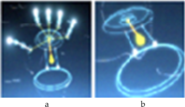
Hand capture by Leap Motion device (a – all fingers stretched; b – all fingers clenched)
Gestures are imitated in the virtual environment for different gripping and handling actions, in this case force gripping (Figure 6).

Screw spanner gripping in various positions
The results of the system implementation and of the handling tests’ performance are positive. The system performs object handling actions in the virtual environment in real time, with a small delay when a number of gestures are performed for detection in a very short period. This delay is attributable to the hardware system, as the data are transferred between the HandProcessor component and the HandSIM component via the serial port. As long as the user does not perform rapid gestures, the delay is not perceptible, In this way, the system implementation can be considered a natural interaction between man and virtual environment.
3.2. The interface controller application
To send motion data to the virtual environment and to test the communication protocol, an application called Interface Controller was developed (see Figure 7). This application emulates human hand movements for each phalanx, object gripping actions and object releasing actions. The Interface Controller application was entirely built using the Microsoft.NET framework. The Interface Controller application uses the functionality provided by the Serial Port class to write and read data via one of the serial ports of a computer.

Visual interface of the Interface Controller component
The application consists of two architectural components, namely:
The HandCommander – which sends data to the serial port and allows data reading from the serial port
The View Component – a visual component that uses the GraspIT application, facilitating signal reception and conversion into commands for a virtual gripper (Figure 8).
The Interface Controller application operates as follows. Upon initialization, each finger is set to the open finger position, which means sending a 0 value to the HandCommander component for each finger. If a finger closure is desired, the value 1 is transmitted to the HandCommander component for that finger. As the visualization component can only access data on the serial port, translation between values 0 and 1 is possible through the HandCommander component. Using this communication model, the gripping action result can be visualized in Figure 8a, performed by pushing the Gripping button. Naturally, each finger can be controlled independently also, as we can see in Figure 8b where the thumb and the index finger are closed, while the other three fingers remain open.
The anthropomorphic gripper simulation in virtual reality in the (a) off position and (b) partially closed position
4. The Prototype
The creation of the mechanical anthropomorphic gripper, RoboHand, can also be described. The RoboHand component is used to reproduce human hand movements in different positions (Figure 9), transmitted by the Leap Motion device. It is controlled via the RoboCommander interface.

System developed for command and control of the RoboHand component
4.1. Constructive and functional particularities
For construction of the gripper, research and analysis were conducted regarding the current condition and construction procedure for existing anthropomorphic grippers [14]. This research highlighted the fact that each anthropomorphic gripper comprises five types of components [15]. Each component's peculiarities can affect the anthropomorphic gripper performance [16–18]. In terms of functionality, the components are classified as:
The result is a mechanical hand with mobility degree five [M=5], with fingers actuated via rotary actuator wires.

Anthropomorphic gripper and human hand
To implement the RoboCommader component used for the command and control of the RoboHand gripper, we used four device types (see Figure 11): (a) a personal computer of 64 bits, (b) an Arduino Leonardo plate and two auxiliary hardware components, namely (c) a USB serial convertor and (d) a driver plate, Adafruit servo, that facilitates the five actuators connection. The data transmission between the RoboHand component ((e) in Figure 11) and the computer is conceptually possible, according to Figure 11.
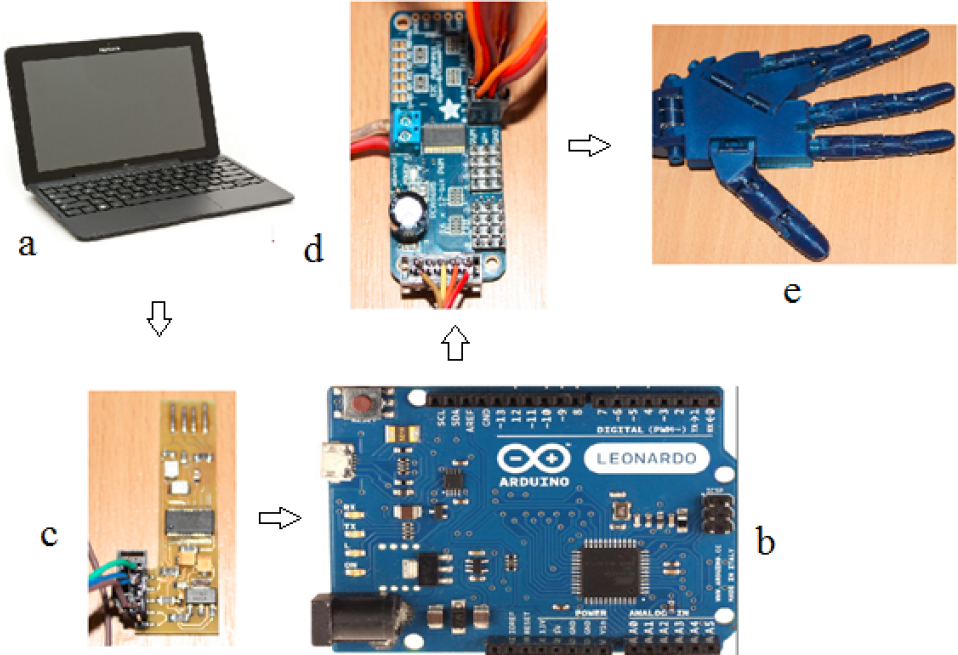
Hardware system of the RoboHAND component's command and control
To transmit data, we developed a control protocol that can be understood both by the PC and the RoboHand component. The purpose of the RoboCommander component is to send data from the PC to the RoboHand and to translate data into command data.
Thus, it can be said that the RoboCommander detailed component modules are as follows:
Communication protocol between the computer and the RoboHand component.
Modul.NET, which sends command data to the RoboHand using the developed communication protocol.
Conversion USB device that permits programmatic connection to the Arduino Leonardo device.
Software control modules for each actuator.
4.2. Testing prototype and command system functionality
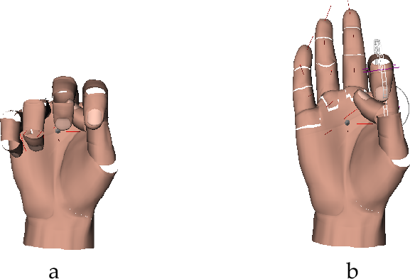
To test the RoboHand component, we conducted an experiment consisting of mimicry of the movement of the human hand in different positions. To do this, different configurations of the fingers were captured with the Leap Motion device and were sent to the RoboHand prototype through the RoboComnmander module. Each finger movement, both in the open and closed position, was captured using the Leap Motion device (Figure 12). These were then sent to RoboHand component via the RoboCommander component (Figure 13).
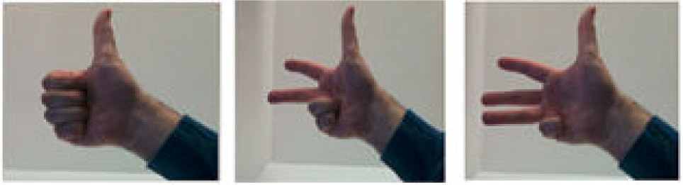
Human hand movements captured with the Leap Motion device

RoboHand anthropomorphic gripper movements corresponding to configurations captured by the Leap Motion device
To test the whole system performance, various gripping tests were conducted using different objects. The gripping system structure for the gripping experiments can be seen in Figure 14.
The experimental object recognition system, SpatialVision, and the command system of the RoboHand gripper, exposed through the RoboCommander interface, were used in the experiment. Its objectives were to record individual performances of the software modules made for hand capture, gripper control and gripping in both a virtual and physical environment, and to test the command and control strategy of the whole system proposed in this paper.
To this end, we defined a series of system evaluation criteria, including:
Setting the efficiency of the objects recognition system.
Setting the efficiency of human hand motion detection.
Setting the efficiency of the command and control system of the anthropomorphic gripper to perform precision and power gripping.
Setting global efficiency of the command and control strategy with the final purpose of automating the gripping process.

The gripping system structure
4.2.1. Experimental research on the assessment of the efficiency of object recognition
The SpatialVision system developed in this paper is responsible for a number of functions, including:
Recognition of the class to which the object belongs, thereby reducing the search space for the object in the database.
Recognition of the object based on image analysis and comparison of points of interest between the object detected in the image and objects in the database.
Generation of a three-dimensional model of the recognized object, creating a COLLADA-XML file to record physical properties of the object.
Evaluation of the system is a difficult task because the system depends on many external factors, the most important being:
light conditions
video device quality
capture dimensions
human operators
To assess the SpatialVision application developed in this paper, we carried out a series of experiments that targeted the system's ability to cope with variations in these external factors.
a. Experiment conception
The objective of this experiment is to test the effectiveness, in terms of contrast, of the application of various lighting conditions and various surface backgrounds on which the object is placed. This is foundational to our investigation, as object recognition is the first step in generating the 3D model.
Lighting conditions represent a significant challenge to the visualization system and the video analysis area in general. For the experiment, we used an advanced video device, Camera Web Logitech BCC950 Conference Cam, Full HD, with characteristics as outlined in Table 1. The capture dimension was set to the maximum possible – Full HD format [1920 × 1080 pixels]. The command and control strategy was used to attach the video device to the gripper, which, in turn, was mounted on a robotic arm, thereby excluding the human operator external factor.
Technical specifications of the video device used

The experiment conducted was based on the recognition process of a device, in this case a screw spanner, when lighting conditions change abruptly. Thus, all the frames captured from the video device were numbered and compared to the frames from which the object was recognized.
SpatialVision application analysis

b. Information analysis and results obtained
The impact of variations in light intensity on image analysis translates as difficulty in the differentiation of the object from its background. Increasing the contrast increases the accuracy percent of the result obtained following analysis. We noticed that the best results are obtained if the background and the object to be recognized tend to the limits of the RGB lines area. Figure 15 demonstrates variation of recognition success according to contrast level.

Variation of recognition rates depending on contrast
4.2.2. Experimental research on evaluating command and control strategies to optimize the gripping process
The aim of the strategy defined in this paper is to facilitate the command and control process of gripping, especially relating to anthropomorphic grippers, which have a high number of joints. To highlight the usefulness of the new approach we conducted two experiments that consider the following tasks:
Performing precision or power gripping actions for objects of different shapes.
Performing gripping actions for a single object, repeatedly, to test the replicability of the method presented.
Conception of the command and control strategy test experiment
The objective of the experiment was to grip a tennis ball, a bearing, a shaft and a screw spanner. The latter case is presented in detail here. The experiment is conducted as follows:
The object to be gripped is recognized using the SpatialVision application based on the image analysis, and the 3D model is loaded in the GraspIT application.
The user gesture is recognized and sent to the gripping test module and the RoboHand component is preconfigured to grip the object.
The object is gripped in the physical environment by the RoboHand component. Proper gripping of the object is tested in the gripping test component and the values of the angles between the phalanges are sent to the anthropomorphic gripper using the RoboCommander interface, which interprets these values and actuates the RoboHand component fingers.
Data recorded by the capture interface are interpreted by the virtual gripping test module for the kinematic model calculation and calibration of an anthropomorphic gripper. Fingertip positions are calculated in 3D space. These positions are then transferred to the physical environment, XYZ, using the RoboCommander interface. To grip a screw spanner, force gripping is performed. The virtual gripper and the screw spanner are positioned according to Figure 16. For the gripping operation, the hand in Figure 17 is moved. The result of the gripping action can be seen in Figure 18 (virtual environment) and Figure 19 (physical environment).

Screw spanner and robotic hand in the virtual environment from different perspectives before gripping

Movements to grip the screw spanner, made above the Leap Motion device

Human hand gripping a screw spanner in the virtual environment from different visualization perspectives

a. Gripping components test for an example object, in this case a screw spanner. b. Testing gripping safety by rotating the object through 90 degrees.
Figure 19a shows the object gripping by the anthropomorphic gripper following gesture commands captured and transmitted by the Leap Motion device. Figure 19b demonstrates the gripping safety by rotating the gripped object through 90 degrees.
In order to demonstrate the validity of the proposed solution, two grasping examples are presented. In the first example, the grasping of a shaft is demonstrated. Finger movements are transmitted via the Leap Motion sensor to the prototype hand, which executes the grasp action (see Figure 20).

Grasping of a shaft by transmitting data from the Leap Motion device to the gripper
The virtual simulation is shown in Figure 21. The prehension stability is tested by attempting to drag the shaft from the grasping RoboHand, as can be seen in Figure 22.

Different perspectives of the grasped shaft in the virtual environment

Testing the grasping stability
The second example consists of grasping of a bearing. In this example, the quality of grasping and its repeatability was also tested. The repeatability of grasping was tested by running the experiment five times using the same command and control strategy. The experiment comprised the following steps:
Loading the bearing model in the GraspIT simulator.
Recognizing and transmitting the grasping command to the testing simulator
Transmitting the action to the RoboHAND component for grasping the object
Recognizing and transmitting the release command.
Repeating the experiment by executing steps 1–4 again, for a total of five executions.
In order to configure the experiment, the virtual gripper is initialized along with the virtual object, as seen in Figure 23a. Simultaneously, the RoboHand component and the bearing are positioned in the physical environment, as shown in Figure 23b.

Positioning of bearing and virtual gripper in (a) the virtual environment and (b) the physical environment
The same results were obtained in each of the five executions of this experiment. The positioning and grasping action were identical between the virtual and real environments, and were easy to configure (Figure 24).

Grasping the virtual bearing
In the physical environment similar results to those in virtual environment were obtained with regard to the positioning of the gripper toward the bearing (see Figure 25).
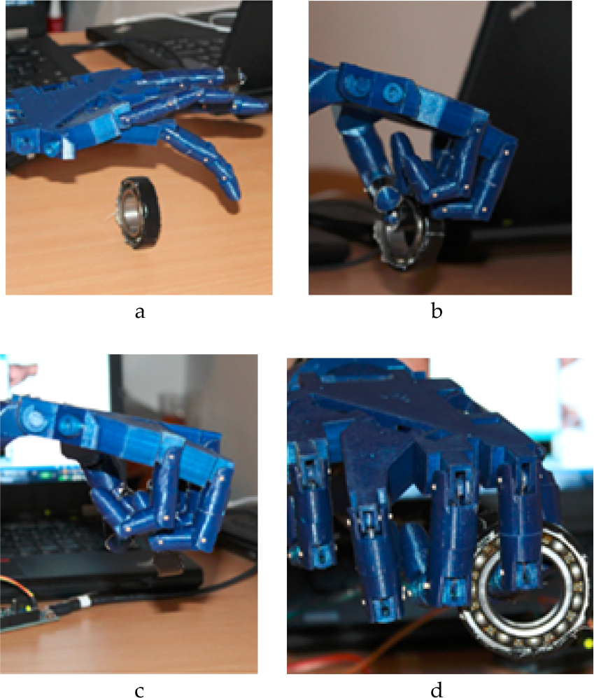
Grasping action of a bearing by the RoboHand component, which was executed five times
Conclusions can be drawn based on the realized experiment and its empirical results, namely that the grasping of a bearing can be executed in a repetitive manner using the command and control strategy defined in this paper, and that this is a valid grasping method for other objects presented in this paper.
5. Conclusions
Regarding the results demonstrated in this paper, the following conclusions can be formulated:
The Leap Motion device enables natural interaction between the user and virtual reality at the level of gestures, comparable to the interaction based on data gloves. We found that the Leap Motion device facilitates human hand gesture recognition with a high degree of accuracy.
The system presented provides an interface through which a virtual hand can be directly animated using a human hand. Once animated, this virtual hand can perform various actions in the virtual environment with ease.
Procedures based on image analysis can be generated to detect, monitor and recognize human hand gestures in an efficient manner using image sensors.
Thus, we conclude that object recognition has a high accuracy rate where contrast between the object and its background is high. Evaluation of the interactive and natural command procedure of an anthropomorphic gripper, both virtual and physical, from the perspective inexperienced users was also performed.
The most important experiment in this study aimed at assessing the role of the command and control strategy through a comparative study of the gripping process. The utility of this approach was noted, not only in the case of anthropomorphic gripping. Due to the interconnection of command and control strategy components, a high level of flexibility is possible in gripping objects of different shapes.
Footnotes
6. Acknowledgements
We express our gratitude to the Company Cloos, Germany, and its Romanian representative, Robcon, which partly sustained these works.