
Abstract
A multimodal actuator is proposed to fulfil the different walking patterns of a power-assisted knee exoskeleton. With this actuator, the exoskeleton leg can realize several modes of operation, including series elastic actuation, stiff position control and energy storage and release. The energy amplification characteristics of the multimodal actuator in the series elastic mode are analysed. A dynamics model was established to study how series elasticity and the equivalent mass of transmission influence a power source, such as an electric motor. The results, in both simulation and experiment, show that series elasticity can amplify actuator power output, and the power output of a multimodal actuator is greater when the equivalent mass of the transmission mechanism is smaller. This research into multimodal actuator energy amplification supplies important insights into the design of artificial systems that can more closely approximate the performance of biological systems.
Keywords
1. Introduction
A power-assisted exoskeleton leg is an anthropomorphic mechanism, capable of assisting the motions of a lower limb. In recent years, different types of powered exoskeletons have been developed [1–4]. Although significant advances have been made in the exoskeleton robot design, all of these existing robots are actuated and controlled using conventional engineering techniques, realizing specific tasks with narrow performance goals, where what is required is a wide range of autonomous exoskeleton robot behaviours, capable of responding to uncertain, complex walking environments [5]. In an effort to increase the versatility of actuators, we present an actuator that combines motor, spring, brake and clutch elements, producing a multimodal actuation of the power-assisted knee exoskeleton. Based on a small-sized brake block that can generate relatively large holding forces, the actuator is capable of instantaneously switching between different modes, including passive, stiff, series elastic, etc.
Many robotics researchers have noted that series elasticity is important for energy storage and release during robot running or hopping, and that elasticity is also important for reducing the output impedance of the actuator and filtering shocks [6–9]. The series elastic actuator (SEA) is an excellent compromise, realizing low-impedance output and power amplification. The SEA was first developed at MIT [10], involving springs attached to a motor in series to mimic many of the desirable properties of human muscles. SEAs have since been applied in humanoid robots [11–12], rehabilitation robots and power-assisted exoskeletons [13–15]. Power output is an important characteristic for evaluating the capacity of an SEA. Roberts and Marsh [16] found, in their study of a simple frog jumping model, that series elasticity was beneficial for muscle work output. Hollander et al. [17] studied variable series elasticity in robotics for power amplification. Paluska and Herr [18] put forth a simple model to quantify the capacity of series elasticity to increase power output from an actuator. Their results showed that an appropriate spring constant increased the peak power delivered to the inertial load over a limited stroke.
In this paper, we present an actuator that combines the motor, spring, brake and clutch elements to produce multimodal actuation. Based on a small-sized brake block that can generate relatively large holding forces, the actuator is capable of instantaneously switching between different modes, including passive, stiff, series elastic, etc. We studied the power amplification of the multimodal actuator in the series elastic mode. A dynamics model was established to investigate how series elasticity and the equivalent mass of transmission influence a power source, such as an electric motor. We considered only force-velocity source limitations, not force-length limitations.
The rest of this paper is structured as follows: section two describes the mechanism and design of the multimodal actuator. The power amplification analysis of the multimodal actuator in the series elastic mode is studied in section three. Section four covers the power amplification experiment and section five concludes the paper, discussing further challenges.
2. The Design of the Multimodal Actuator
2.1. Design overview of the multimodal actuator
Fig. 1 shows a computer-aided design model of the multimodal actuator, consisting of a servo motor, a screw-nut transmission mechanism, a spring, two guide rails, two brake rails and three brake blocks. The three brake blocks are mounted onto a pair of guide rails. Running parallel to the guide rails is a pair of brake rails that pass through each slide. Linear bearings are used between the brake blocks and guide rails in order to reduce friction losses. The dimension parameters of the multimodal actuator and motor selection are implemented based on the motion demands of a power-assisted knee exoskeleton. The servo motor of the multimodal actuator is a Maxon RE-30 DC motor with a power rating of 60 W and a continuous torque rating of 85 mNm. The motor features a proprietary emulated encoder with a resolution of 500 counts. The ball screw driven by the DC motor has a range of 200 mm, a diameter of 8 mm and a lead of 2 mm. The spring of the multimodal actuator is made of steel with a stiffness of 1 N/mm and can be exchanged to change the stiffness. The spring connects the power supply and load. The use of the spring simulates the characteristics of the human muscle and adapts to changes of external load. The three brake blocks are named brake block one, brake block two and brake block three. Brake block one is connected on one side to the spring and to nothing on the other. Brake block two is the centre slide, bridging the spring on one side and the nut of the ball screw on the other. Brake block three mounts the rotational DC motor on one side and a ball screw on the other. The brake block is the main focus of the design due to this mechanism generating a large dynamic range of braking forces while maintaining rapid transitions. Each brake block is controlled by a brake motor (RB-150CS) that engages or disengages the brake pads such that the brake block can be fixated or released with respect to the brake rails. The brake block mechanism is shown in Fig. 2. The brake motor rotates the gear and the gear pushes the rack up and down. The rack is connected to the end of the push rod and the other end of the push rod is connected to the push plate. When the rack moves down, the push rod pushes the push plate against the brake rail and in this way the brake block is fixated against the brake rails. Otherwise, the brake block is released from the brake rails.

Multimodal actuator

Brake block mechanism
2.2. Motion modes of the elastic actuator
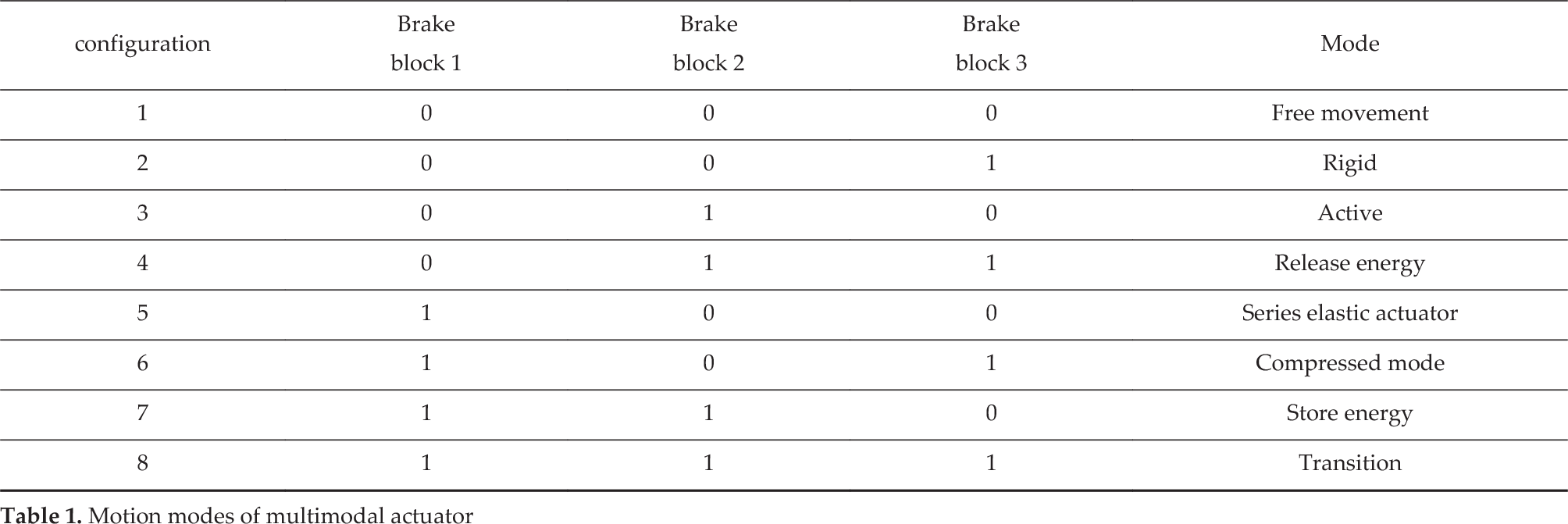
It can be seen from Fig. 1 and Fig. 2 that the brake block has two kinds of switching mode. When the brake block is in a state of “0”, it indicates that the brake block sliders can move freely on the rail. When the brake block is in a state of “1”, it indicates that the brake block and the guide rail are rigidly connected and the brake block sliders cannot slide on the guide rail. The operating modes of the multimodal actuator can be obtained according to the operation of the motor and the opening and closing mode of the brake block, as shown in Table 1. The multimodal actuator is designed to actuate the rotary joint of the power-assisted knee exoskeleton. The different modes of the power-assisted knee exoskeleton during a motion cycle can be realized by changing the multimodal actuator operating modes, as shown in Fig. 3. Firstly, the three brake blocks are disengaged and the shank limb is put in contact with the ground. The actuator is passive and completely free to move, as shown in Fig. 3(a). Then, as shown in Fig. 3(b), brake block two is engaged, while brake blocks one and three are disengaged. The motor rotates and drives the screw-nut mechanism. The distance between brake block two and brake block three decreases and the knee angle, θ (as shown in Fig. 3), increases. The shank limb flexion is directly controlled by the motor and precise control of the leg can be obtained during this stiff position controlled mode. In Fig. 3(c), brake block two is engaged, while brake blocks one and three are disengaged. The motor counter-rotates and drives the screw-nut mechanism. The distance between brake block two and brake block three increases, and the knee angle, θ, decreases. The shank limb extends until it touches the ground. In Fig. 3(d), brake block two is disengaged and brake blocks one and three are engaged when the pressure sensor, mounted on the end of the shank limb, detects the force increase. The motor rotates continuously and the spring is attached to the motor in series to filter instantaneous impact. In Fig. 3(e), the motor rotates continuously and the spring is compressed to maximum compression. This mode allows energy to be stored in the spring for energy efficient motor control. At last, the motor counter-rotates rapidly. The stored kinetic energy is released and the shank limb is bounced. This mode allows the actuator to increase power output, as shown in Fig. 3(f).
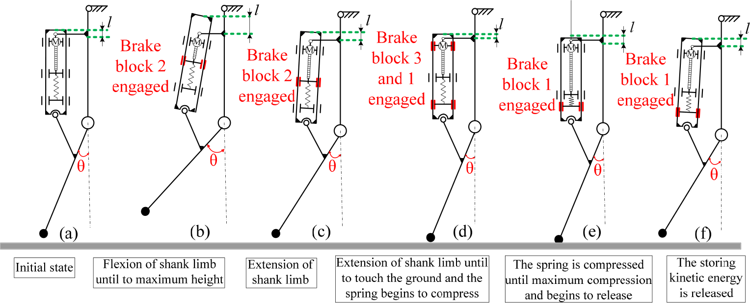
Different modes during a motion cycle (the distance l between the brake rail and the motor is changed in different phases, and the knee angle θ is also changed in different phases)
Motion modes of multimodal actuator
3. Energy Analysis of the Multimodal Actuator
3.1. Model of the multimodal actuator in rigid mode and simulation
The multimodal actuator in series rigid mode is simplified as shown in Fig. 4. The motor is modelled as an ideal force source

This equation can easily be solved for the time trajectories of the mass:


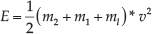
The energy of the multimodal actuator is as follows:
Model of the multimodal actuator in rigid mode

Normalized energy in rigid mode
Fig. 5 shows the energy delivered for a given normalized stroke length
3.2. Model of the multimodal actuator in series elastic mode and simulation
3.2.1. Model of the multimodal actuator in series elastic mode
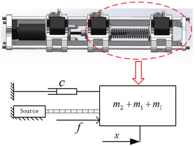
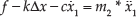
The multimodal actuator in series elastic mode is simplified as shown in Fig. 6. The motor is modelled as an ideal force source


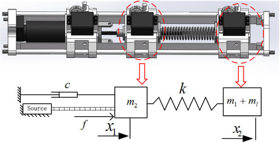
Model of the multimodal actuator in series elastic mode
The transfer functions can be derived as follows:

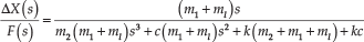

The total energy


3.2.2. The influence of spring stiffness on the multimodal actuator energy output
The normalized method was adopted to analyse the effect of different spring stiffness for the multimodal actuator's energy output. The f, c,

Elastic potential energy of spring with different stiffness

Kinetic energy of load under different spring stiffness

Total system energy under different spring stiffness
The X axis in Fig. 7, Fig. 8 and Fig. 9 is the normalized actuator stroke. The Y axis is the normalized energy at the extent of the stroke. The energy delivery is plotted for various values of dimensionless series elasticity, k. Fig. 7 shows that the peak elastic potential energy decreases with increasing spring stiffness. First, the elastic potential energy increases for a given k then the energy gradually decreases as the actuator stroke increases to a certain value and the elastic potential energy does not increase over any X when the k increases to a certain value. Fig. 8 shows that peak kinetic energy decreases with increasing spring stiffness. Fig. 9 shows that, for sufficiently large values of k i.e.,
3.2.3. The influence of equivalent mass on the multimodal actuator energy output
The elastic potential energy of the spring under different equivalent mass is shown in Fig. 10, the kinetic energy of the load under different equivalent mass is shown in Fig. 11 and the total system energy under different equivalent mass is shown in Fig. 12. The

Elastic potential energy of spring under different equivalent mass

Kinetic energy of load under different equivalent mass

Total system energy under different equivalent mass
Fig. 10 shows that the equivalent mass
4. Energy Amplification Experiments of the Multimodal Actuator
A photo of the experimental setup is shown in Fig. 13. The mechanical portion of our test setup consisted of the multimodal actuator and supporting bracket. The electronics of experimental setup consisted of a power supply, brake motor, sensors, microcontrollers and a host PC. For the motor drivers, we employed MAXON EPOS2 50/5, which was also used as the interface for the analogue sensors in the prototype of the multimodal actuator. A linear potentiometer was installed on brake block one and brake block two to measure the distance between them.

A photo of the experimental setup
Two experiments were performed to test the influence of spring stiffness and equivalent mass on the multimodal actuator energy output. The sampling frequency of the data was 100 Hz. The X axis parameter was time t. The linear potentiometer gathered
The spring energy output under different spring stiffness is shown in Fig. 14. The results of the experiments in Fig. 14 show that the series elasticity produced a power amplification characteristic, and the power increased with increased spring stiffness. The spring output under different equivalent mass is shown in Fig. 15. The results of the experiments in Fig. 15 show that energy amplification capacity decreased with increasing transmission mass. This shows that the work output of the multimodal actuator was better when the equivalent mass of the transmission mechanism was smaller. These results imply that the equivalent mass should be reduced in the design of the multimodal actuator to improve the energy output performance of the actuator.

Spring energy output under different spring stiffness

Spring energy output under different equivalent mass
5. Discussion
We propose a multimodal actuator that can achieve various motions by incorporating a motor driving a screw nut, a series with a spring and corresponding brake pads. The motion modes of the multimodal actuator included passive, stiff and series elastic, etc. The energy amplification characteristic of the multimodal actuator in series elastic mode was analysed. The results of both numerical simulation and experiments showed that energy amplification can be achieved for a multimodal actuator. A simplified model was used for demonstration. We observed that an appropriate spring constant increased the energy output of the system, which is to say the spring constant had a great effect on the actual mechanical operation. This suggests that, by including a series spring in a robot or actuator, we can reduce the power requirements of the motor. We also analysed the influence of equivalent mass on the multimodal actuator energy output and the results of this investigation showed that energy amplification capacity decreased with increasing transmission mass. This suggests that we can reduce the equivalent mass
Preliminary experiments were performed to test the model's predictions. We can see that the model is in qualitative agreement with the experimental data. The model and experimental results both highlight the importance of series elasticity for energy amplification of the multimodal actuator. It is important to note that different mechanism parameters for the multimodal actuator will yield different energy amplification results. It is also important to note that this is an independent study of the actuator and does not predict actual dynamic behaviour of the multimodal actuator under a power-assisted exoskeleton leg control system, or disturbances.
6. Conclusions
A robot actuator is often designed for a specific task with narrow performance goals, whereas, in uncertain motion environments, a robot must be able to perform a wide range of output modes. We proposed an actuator that combined motor, spring, brake and clutch elements to produce multimodal actuation for increasing the versatility of a lower limb power-assisted exoskeleton robot. Dynamic coupling, in the form of brakes and clutches, enabled the motor and spring to be engaged and disengaged within a single actuator. With this actuator, the exoskeleton leg can realize several modes of operation, including series elastic actuation and stiff position control, as well as the potential to store and release energy. In this paper, we focused on the power amplification of the multimodal actuator in series elastic mode. A dynamics model was established to study how series elasticity and equivalent mass of transmission influence a power source, such as an electric motor. The results, in both simulation and experiment, show that series elasticity can amplify actuator power output and the equivalent mass
Footnotes
7. Acknowledgements
This work is supported by the National Science Foundation of China (Grant NO.51205182) and the Innovation Foundation of NJIT (Grant NO.CKJA 201501, JXKJ201510).