
Abstract
Optimal control of a Stewart robot is performed in this paper using a sequential optimal feedback linearization method considering the jack dynamics. One of the most important applications of a Stewart platform is tracking a machine along a specific path or from a defined point to another point. However, the control procedure of these robots is more challenging than that of serial robots since their dynamics are extremely complicated and non-linear. In addition, saving energy, together with achieving the desired accuracy, is one of the most desirable objectives. In this paper, a proper non-linear optimal control is employed to gain the maximum accuracy by applying the minimum force distribution to the jacks. Dynamics of the jacks are included in this paper to achieve more accurate results. Optimal control is performed for a six-DOF hexapod robot and its accuracy is increased using a sequential feedback linearization method, while its energy optimization is realized using the LQR method for the linearized system. The efficiency of the proposed optimal control is verified by simulating a six-DOF hexapod robot in MATLAB, and its related results are gained and analysed. The actual position of the end-effector, its velocity, the initial and final forces of the jacks and the length and velocity of the jacks are obtained and then compared with open loop and non-optimized systems; analytical comparisons show the efficiency of the proposed methods.
1. Introduction
The main advantage of a Stewart robot as a kind of parallel manipulator is its high load-carrying capacity along a specified path or between two predefined points. This capability makes it suitable to be used in industrial environments to guide a machine or tool along a desired path within a large workspace and high stiffness. Therefore, control and optimization of the jack's force with the highest tracking accuracy can be a valuable goal to minimize the additional consumed power and energy. However, due to the parallel characteristics of such a robot, its control procedure is more challenging. In order to achieve good control at the same time as optimizing the system of the robot, a dual sequential controlling loop of the optimal feedback linearization method is employed in this paper, while the dynamics of the jack are also modelled to increase its accuracy.
This mechanism was first developed with six DOFs by Stewart for a flight simulator. Its end-effector was a triangle and spherical joints were used for its six actuators [1]. Hunt then used it as a parallel robot. It was employed for manipulation and as a flight simulator [2]. One of the most important driving simulators was also designed and manufactured in Lowa University using this robot [3]. While a proper workspace had been provided by the aforementioned research, they were controlled in an open loop manner, which decreased its efficiency with respect to disturbances or parametric uncertainties. The modified closed-loop systems of these kinds of robots were developed for conducting manipulation processes such as milling or gridding operations. They were first designed and manufactured for the IMTS industrial exhibition (Variax) [4]. Force control in such applications was performed by Burdet [5] to promote its manipulating applicability. An accurate positioning mechanism was also developed using this kind of robot (ESRF), which was designed to emit an X-ray with an exact coordinate and frequency. This level of accuracy was only realized by the aid of a closed-loop Stewart robot that was manufactured by INRIA [6]. Other samples of closed-loop Stewart platforms are the Gough-Stewart platform, which was designed and manufactured in order to isolate the vibrations of the US aerial military (VISS) [7], and MARS as a 6-UPS Stewart robot that was employed as a surgery assistant [8]. To provide the required precision for this surgical robot, adaptive control was implemented by Lebret and Ghobakhloo to increase the accuracy of the robot [9,10]. Adaptive control was also employed for this robot by Ryo [11] and non-linear friction was compensated in this research. This method was also used in [12] based on the FUZZY approach. Robust non-linear control methodology of the Sliding Mode is another closed-loop methodology, which was implemented for a single stage of a Stewart platform in [13,14] to eliminate the destructive effects of external disturbances and parametric uncertainties. A Stewart platform, which was used for carrying an antenna, was also controlled in a closed-loop manner by Iqbal using a robust approach [15].
The aforementioned cases do not employ any optimization tool to save energy. Tzafestas [16] and Omran [17] optimized the closed-loop Stewart robot using a genetic algorithm. Since a heavy off-line calculation process is required in this method, it is not applicable for online applications. Fundamental mathematics of analytic optimal control applied to robotic arms is presented in [18], which is more suitable for online optimization. One of the most applicable closed-loop optimal controllers designed especially for linearized robotic systems is LQR. This method was improved in [19] based on robot dynamic compensation. One of the examples of parallel robots that are controlled and optimized using LQR is cable robots, which are another version of parallel manipulators and are optimized in [20] based on LQR. However, this kind of robot suffers from low stiffness and they are not suitable for the exact manipulation of heavy loads. On the other hand, dynamics of the jacks are not considered in most of the aforementioned research, while they can have a significant effect on the manipulation process, especially for the micro-scale cases with light loads. Dynamics of the jack are studied in [21], while no optimization was employed to control its force with the presented jack dynamics. All of the aforementioned controlling strategies were based on workspace control of the robots, while in experimental tests, joint space control is one of the most significant complementary controllers, which should be considered to provide the acceptable accuracy of the system. Sequential control strategy, which is required for simultaneous control of the jacks and end-effector in experimental studies, was only considered in [22] by Almonacid for a single-stage Stewart robot; however, no optimization strategy was suggested by him to optimize the loops.
As a result, it can be seen that some aspects of the control study of this robot have hitherto been ignored. In this paper, a feedback linearization algorithm is employed to control the non-linear dynamics of this robot, which is a confident, fast and Lyapunov-based stable method of controlling motion. In addition, linearization of the equations helps us to use the LQR method to optimize the system for a defined objective function, which provides the highest accuracy with the lowest amount of consumed energy. In addition, in order to increase the accuracy of the system, the mass and dynamics of the jacks are also modelled, and are coupled to the dynamics of the main system. Finally, two sequential controlling loops are employed to doubly increase its tracking accuracy, in which — in the inner loop — the semi-linear dynamics of the jack as the joint space of the robot are controlled using PID (each 0.01 sec) while the non-linear dynamics of the end-effector as the workspace of the system are controlled using the proposed optimal feedback linearization method (each 0.1 sec).
In the second section of this paper, the dynamics of the Stewart robot and jack are represented and the coupled dynamics of their integrated system are derived. The proposed control strategy of feedback linearization is explained in the third section, while the optimization process and joint space control of the robot in a sequential manner is performed in the fourth section. Finally, the efficiency of the proposed algorithm is shown in section five by the aid of a comparative and analytic simulation study in MATLAB for a six-DOF Stewart robot. It is shown that the proposed controlling method, together with considering the dynamics and control of the joint space of the jacks, can successfully provide the tracking accuracy while minimizing the controlling effort.
2. Dynamics Scheme
The kinematics of a Stewart robot specifies the relation between the length of the jacks and the position of the end-effector:

where L is the length of the jacks, X L and Xω are the linear and angular DOFs of the end-effector and SJ is the Jacobian matrix of the Stewart robot, which can be calculated using the following partial differentiation:

The dynamic equation of the robot can be described via equation (2) for a six-DOF Stewart robot of figure (1) [1]:

where D is the inertia matrix, C is the Coriolis matrix of the robot, g is the gravitation vector and T is the final force of the jack on the end-effector along the jack direction. In addition, we have:


Scheme of a spatial sample of a Stewart robot
Here, m and I are the mass and inertia momentum of the end-effector and I 3 is a diagonal unique matrix of size three. In figure (1), On is a global coordinate attached to the fixed lower platform of the robot, while Ob is local coordinate attached to the moving upper platform. Translational movements of the end-effector relate to the global coordinate, while the rotational ones relate to the local coordinate.
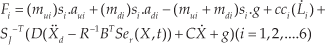
In addition, the dynamic equation of the jacks of the robot (figure (2)) can be extracted as below [19]:
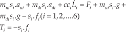
where cc is the viscous damping of the jacks, m u is the mass of the moving part of the jacks, m d is the mass of the fixed part of the jacks, a u and a d are the same variables for the acceleration of these parts, s i is the unit vector of the jacks along their actual direction, F is the initial force of the jacks, T is the final force of the jack on the end-effector when they both lie along the jack's direction and f is the final force in Cartesian space.

Scheme of the dynamics of a jack [19]
Coupling the dynamic equation of the end-effector (1) with the dynamic equation of the jack (4) results in the required initial force of the jacks for a desired path, which can be employed for the inverse dynamics of the robot:

The flowchart of the complete simulation of a Stewart robot's dynamics, including inverse and direct dynamics of both end-effector and the jack's plants, is depicted in the following figure:

Flowchart of the dynamics of a Stewart robot considering the dynamics of its jack
3. Control Scheme
The related state space for the aforementioned Stewart dynamic equation can be expressed as below [20]:

In order to optimize the system using LQR as a linear closed-loop optimizer tool, the exact feedback linearization method is applied to convert the non-linear states into linearized space. Not only is this method exact and efficient, but stability is also assured based on Lyapunov criteria. Considering the fact that input signals exist in all of the non-linear terms of the state space, one can conclude that the system is feedback linearizable. Therefore, the proper final jack force should be considered as equation (6), as the control input of the inner loop of the feedback linearization:

where ν is the control input of the outer closed loop of feedback linearization and can be selected as below to create controllable and stable error dynamics that can be optimized using the LQR method:
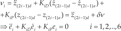
where K iD and K iP are the derivative and proportional controlling gains of the end-effector and e is the error of the end-effector DOFs. Index d denotes the desired value of the parameters, while index a shows its actual one. By the aid of the aforementioned outer-loop controlling inputs, the state space can be linearized as below:

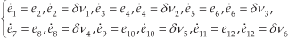
Therefore, the state space of the error can be defined as below, which is linear and optimizable by the aid of LQR:
4. Optimal Control Implementation
Two main constraints are considered here to optimize the performance of the system. These constraints increase the robot's performance during its mission of carrying a machine along a specified path or between two points. The first is the required force of the jacks and the second is the tracking error of the end-effector, which are supposed to be minimized simultaneously in a compromising process with the aid of the LQR method. Linearizing the system by the aid of feedback linearization theory has made it possible to optimize the outer control input gains with the aid of the LQR method. Jack force and end-effector errors are the terms of objective function to be minimized for the movement of the end-effector within a predefined trajectory. Therefore, the cost function can be defined as below:
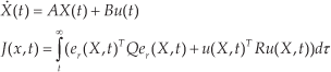
where Q is the gain matrix of accuracy and R is the gain matrix of control input, and both of them are positive definite matrices. In addition, A and B are the state space matrix of the system, J is the objective function of the system that should be minimized, e
r
is the error of the states and u is the optimal outer-loop control signal of the system, which is the same as

Solving the aforementioned Riccati equation for S results in the following optimal control input:

Therefore, the optimized value of the final jack force can be calculated in this manner:

Considering the explained dynamics of the jacks, this final force of the jack should be improved according to the following initial force of the jack:
where a should be evaluated using the inverse dynamics of the system. The aforementioned optimal control can be summarized as in the following flowchart:

Flowchart of the optimal control of the Stewart robot
Finally, in order to doubly increase the accuracy of the end-effector in experimental tests, a sequential controlling strategy is designed and proposed in which — in the inner loop — the semi-linear dynamics of the jack are controlled using a simple PID controller (each 0.01 sec), while the non-linear dynamics of the end-effector are controlled in the outer loop using a non-linear method of optimized feedback linearization strategy (each 0.1 sec). Therefore, the improved closed-loop optimal initial force of the jack can be calculated as below:
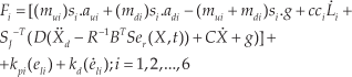
where el and

Flowchart of the proposed sequential controlling strategy for the optimal control of a Stewart robot
5. Simulation Results
For simulation, a six-DOF spatial Stewart robot is considered for which its properties are expressed in table (1), and its related kinematics and kinetics results are extracted for a predefined desired path. A scenario is considered here to show the effect of considering the jack's dynamics, besides implementing the optimal control.
The properties of the simulated spatial Stewart robot

The aforementioned spatial Stewart system has the following state space equation:

This state space results in the following optimal control signal:

Based on the aforementioned optimal controlling strategy, the required initial and final force of the jacks can be calculated as below:

where indexes d and a denote the desired and actual values of the parameters, respectively. In order to verify the efficiency of the proposed controlling strategy, a 55 kg load is placed on the end-effector of the robot and a desired path of equation (19) is supposed to be tracked:

Figure (6) shows the comparison between the actual path of the open loop system and the robot that is controlled using the aforementioned optimal control strategy:

Comparison of the actual path for open-loop and closed-loop systems
It can be seen that in the closed-loop optimal system, its accuracy increased considerably (by more than 30%) as a result of increasing a negligible amount of jack force, while z is negative since the positive direction of the Cartesian coordinate is set towards the ground. The velocity of the robot's end-effector is depicted in figure (7):

Velocity of the end-effector movement
For the initial moments, a large amount of acceleration is produced, which is the result of an initial shock, and this small jump is then smooth for the rest of the simulation. It can be seen that the movement is almost linear according to the desired path, and so its velocity is almost constant, which is producible using the ordinary hydraulic jacks. The lengths of the jacks during the process are obtained as below:

Length of the jacks
The length of the jacks changes in a reasonable range of about 0.3 m in order to provide the desired end-effector movement that is applicable for ordinary available jacks. All of the six jacks follow the pattern of two trends in order to realize the desired path motion of the end-effector. In addition, the velocities of the jacks’ elongation can be seen in figure (9):

Velocity of the jacks’ elongation
As was expected, the rate of the jacks’ elongation was also small enough, and so it is applicable for the ordinary available viscous jack without extra resisting force. The comparison of the initial and final force of the jacks due to the mass and dynamics of the jacks is shown in figure (10) for the non-optimized system:

Comparison of the initial and final force of the jacks for a non-optimized system
It can be seen that the required initial force of the jack is a little different from its final value. This difference, which is related to the mass and acceleration of the jack, seems to be negligible here because the mass of the jack is negligible compared to the robot's load. It is obvious that considering the modified value of the jack force results in more accurate tracking of the end-effector. This difference is more important for the micro-scale systems, or for the systems in which the load of the end-effector is negligible compared to the mass of the jacks. The same comparison is represented in figure (11) for the optimized system:

Comparison of the initial and final force of the jacks for the optimized system
The comparison of the jack's force between the optimized and non-optimized system is shown in figure (12). In this figure, the simple system is the system that is controlled by regular feedback linearization (with manual controlling gains) rather than the proposed optimal controller of this paper (LQR + feedback linearization). It can be concluded from the figure that using the aforementioned optimal controller results in a lower absolute amount of required force in the jacks, while the accuracy of the optimal system is better than that of the simple one, according to figure (6). This result shows that the proposed optimal controller provides the same degree of accuracy with the minimum consumption of energy. However, it is obvious according to figures (10, 11) that, in both cases of optimized and simple controllers, the required initial force is larger than the final one to compensate for the mass and dynamics of the jack, which was expected.

Comparison of optimized and simple force of the jack (jacks 2,4,6)
6. Conclusion
In this paper, a new method was proposed to secure optimal and accurate control of a Stewart robot that is supposed to carry a machine along a specified path. The extreme non-linear dynamics of this parallel robot were linearized and controlled using the feedback linearization method. Subsequently, this linearized space was optimized using the LQR approach that results in accurate tracking using the minimum required energy. In this paper, in order to increase the accuracy of tracking, the mass and dynamics of the jacks were considered and added to the main dynamics of the system. Finally, in order to doubly increase the accuracy of tracking in experimental tests, a system of two sequential controlling loops was proposed, by which in the inner loop the linear dynamics of the jacks are controlled using simple PID (each 0.01 sec), while in the outer loop the non-linear dynamics of the end-effector are controlled using optimal feedback linearization (each 0.1 sec).
The efficiency of the proposed method and modelling was examined by the aid of a series of comparative and analytic simulations and scenarios, which are performed in the SIMULINK of the MATLAB for a six-DOF hexapod system. First of all, it was seen that the proposed designed controller could successfully control the full load end-effector with considerably more accurate tracking rather than in the open-loop system (about a 30% improvement) with a smooth and acceptable velocity profile. Investigating the length and velocity of the jacks showed that the proposed controller realizes the desired path with acceptable and reasonable movement of viscous jacks that are available in industrial environments. It was also seen that modelling the dynamics of the jack results in more accurate results, while the final required forces of the jacks are a little larger than the initial ones, and that this small difference is due to the smaller mass of the jack when compared to the heavy load of the end-effector. The larger the mass of the jack, the greater the force difference. Finally, comparing the jack forces of the optimal and simple controller showed that not only can the accuracy of the optimal system be improved by the aid of the proposed controller, but also that its energy consumption is less than that of the simple system. Therefore, any kind of hexapod or Stewart robot with its extreme non-linear dynamics can be easily controlled in an optimal and accurate way for any desired path, and for any size of the load of the end-effector within its large workspace, by the aid of the proposed controlling strategy.
Footnotes
7. Acknowledgements
The present research work is supported by Islamic Azad University, South-Tehran Branch.