
Abstract
The well-known algorithms, such as the graphic method, analytical method or numerical method, have some defects when modelling the dexterous finger workspace, which is a significant kinematical feature of dexterous hands and valuable for grasp planning, motion control and mechanical design. A novel modelling method with convenient and parametric performances is introduced to generate the dexterous-finger reachable workspace. This method constructs the geometric topology of the dexterous-finger reachable workspace, and uses a joint feature recognition algorithm to extract the kinematical parameters of the dexterous finger. Compared with graphic, analytical and numerical methods, this parametric modelling method can automatically and conveniently construct a more vivid workspace's forms and contours of the dexterous finger. The main contribution of this paper is that a workspace-modelling tool with high interactive efficiency is developed for designers to precisely visualize the dexterous-finger reachable workspace, which is valuable for analysing the flexibility of the dexterous finger.
1. Introduction
Over the past few decades, there have been great strides made in the development of novel dexterous hands in the form of the Stanford/JPL hand [1], Utah/MIT hand [2], DLR hand [3], GIFU hand [4], DLR/HIT II hand [5], Vanderbilt hand [6], Smart Hand [7], DEXMART Hand [8], etc. These hands have been continuously developed to have more functions, which are needed for secure grasping and the manipulation of different and complex objects. All of these functions were created in order to increase the dexterity and manipulability of dexterous hands. The knowledge of the dexterous-hand reachable workspace is crucial in order to achieve dexterous manipulations. The flexibility and graspability of the dexterous hand largely depend on its reachable workspace. Furthermore, the importance of the dexterous-hand reachable workspace lies not only in the planning and control of the dexterous hand's motion, but also in the mechanical design where the reachable workspace is used as a criterion so that the designed dexterous hand has large motion fields.
Combining the participations of the palm with extra degrees of freedom, the reachable workspace of dexterous hands can be defined as the set of points that can be reached by its fingers. In this paper, we only discuss the reachable workspaces of dexterous hands with fixed palms. For computing the dexterous-finger reachable workspace, what researchers are most concerned with is its corresponding shape, which includes the 2D boundaries and 3D surfaces, and which has been studied by graphical, analytical and numerical methods.
Usually, a dexterous finger can be regarded as a 4-R spatial open-chain linkage. The graphic methods are very inconvenient for drawing the 2D boundaries and 3D surfaces of the linkages with more than 3 DOFs (degrees of freedom) [9, 10, 11]. Tsai et al. developed an algorithm to determine the workspace on an arbitrary plane for an n-R robot [12]. The algorithm was based on a linear optimization technique and on small incremental displacements applied to coordinate transformation equations relating the kinematic parameters of the n-R robot. Ceccarelli et al. proposed an algebraic formulation to describe the workspace boundary of general n-R open-chain linkages [13]. This formulation was a function of the dimensional parameters in the linkage chain and specifically of the last revolute joint angle, only. Both Tsai and Ceccarelli utilized the geometric properties to devise analytical algorithms for describing the workspace boundary. These analytical algorithms are often not available or require specialized methodologies, especially for a 3D workspace [14].
Currently, the numerical methods [14–18], such as the Monte Carlo method [15, 16], have been widely adopted. Cao et al. used the Monte Carlo method with Beta distribution to generate the 3D point cloud workspace of the 3-R spatial manipulator [14]. Cui et al. illustrated the workspace of the fingertip in 3D Euclidean space with a numerical algorithm [17]. Based on a stratified workspace boundary search technique, Wang et al. presented a new numerical method for determining the reachable and dexterous workspaces of parallel manipulators [18]. However, the numerical methods still have several drawbacks. First, the densities of the point cloud generated by the numerical methods are not uniform in workspace, which affects the accuracy of workspace boundaries. Second, the numerical methods cannot automatically generate 3D surfaces, so the point cloud had to be imported into some commercial modelling software, such as UGS NX or Solidworks, for generating the 3D workspace [19]. This process is difficult for mechanical designers, who have to master not only the computing software, such as Matlab, C++, but also the 3D modelling software. Third, the designer needs to cost for much extra time in operating these pieces of software to obtain the 3D workspace with low interactive efficiency [20]. Instead, as pointed out in Ref. [14], ‘it is necessary to propose a systematical method to fast and accurate compute the shape and size of 2D and 3D workspace in one software’.
This paper proposes a novel method and develops a prototype software to model the dexterous-finger reachable workspace. With feature recognition technologies, we present a parametric modelling method to construct the precise shape or boundary of the dexterous-finger reachable workspace. Then, we develop prototype software with an ACIS kernel, which can conveniently and automatically model the dexterous-finger reachable workspace. This prototype software with high interactive efficiency is valuable for designers who want to evaluate the kinematic performances of the dexterous finger.
This paper is organized as follows. Sect. 2 describes the displacement equation of the dexterous finger. Sect. 3 constructs the geometric topology of the dexterous-finger reachable workspace. Sect. 4 presents an algorithm to automatically recognize the dexterous finger joints, and calculates the joint distances among the joint axes. The prototype software to generate precise and vivid reachable workspace of the dexterous finger is introduced in Sect. 5. Conclusions and future work are presented in Sect. 6.
2. Displacement Equation of a Dexterous Fingertip
The dexterous finger usually has the metacarpophalangeal (MCP) joint, the proximal interphalangeal (PIP) joint and the distal interphalangeal (DIP) joint. The MCP joint is of the flexion-extension motion and the adduction-abduction motion, and the PIP and DIP joints have the flexion-extension motion. Therefore, the dexterous finger has 4 DOFs that are similar to those of the human finger.
We built a kinematical diagram of the dexterous finger with the Denavit-Hartenberg (D-H) methodology, as shown in Figure 1.

Kinematical diagram of the finger
l1 is the distance between the z1 axis and z2 axis. l2, l3, l4 are the distances among the z2, z3 and z4 axes as the lengths of the proximal phalange, middle phalange and distal phalange, respectively. Four coordinate systems lying on the finger joints are also listed in Figure 1.

where,
With the kinematical parameters of l1, l2, l3, l4, θ1, θ2, θ3, ϕ1, we can calculate the exact positions of the fingertip
3. Finger Workspace Topology
It is well known that the finger motions are combined with the flexion-extension motion and adduction-abduction motion of finger joints, and that the motion sequences of finger joints do not affect the final location of the fingertip. It is obvious that the axes for the flexion-extension motion are perpendicular with those of the adduction-abduction motion. Therefore, the finger motions can be considered as firstly making the flexion-extension motions of each joint, then making the adduction-abduction motion of the MCP joint. If the adduction-abduction motion is forbidden, meaning
3.1. The finger's kinematical data structure
In order to describe the geometric topology of the dexterous-finger reachable workspace, we need to construct an appropriate kinematical data structure, which includes some information of the joint axis ID, joint distances and rotation angles, etc. We created a parameter class
Then, we formed a joint information class

The finger's kinematical data structure
3.2. Workspace solution of the dexterous finger
The entire 2D reachable workspace of the dexterous finger is formed by the flexion-extension motions of the DIP, PIP and MCP joints. According to the robot kinematics, the complete 2D reachable workspace boundary curves can be obtained via the following motion sequences: 1) DIP joint flexion motion, 2) PIP joint flexion motion, 3) MCP joint flexion motion, 4) DIP joint extension motion, 5) PIP joint extension motion and 6) MCP joint extension motion. Therefore, this motion sequence is general for similar dexterous fingers with different kinematical parameters, in order to obtain their 2D reachable workspaces.
Given the exact values of l1, l2, l3, l4, θ1, θ2, θ3 and ϕ1, we built a process with seven steps to obtain the 2D reachable workspace boundary curves

2D and 3D reachable workspaces of dexterous fingers. By using the Monte Carlo method to express the 2D or 3D reachable workspaces, the point clouds, as shown in (c) and (f), are difficult to use to achieve clear2D boundaries and 3D surfaces. This parametric modelling method with geometric topology can generate accurate and vivid 2D contours and 3D shapes of the reachable workspaces, as shown in (a), (d), (b) and (e).
Step 1, Initializing the
Step 2, DIP joint (
Step 3, PIP joint (
Step 4, MCP joint (
Step 5, DIP joint (
Step 6, PIP joint (
Step 7, MCP joint (
By this process, we first construct the entire 2D workspace boundary of the dexterous finger. Then, combining the adduction-abduction motion ϕ1 with these six loci (
For example, if a dexterous finger has
For another example, if a dexterous finger has
Compared with the 2D and 3D reachable workspaces drawn by the Monte Carlo method, it is obviously that both 2D and 3D reachable workspaces with geometric topologies have more vivid, precise boundaries or shapes, which present the whole motion fields of the dexterous finger in 2D or 3D Euclidean space. This is the main purpose of this paper: to innovate this parametric modelling method. Furthermore, this parametric modelling method is suitable to generate the 2D or 3D reachable workspaces of similar dexterous fingers with different kinematical parameters to those of these examples.
4. Feature Recognition of Finger Joints
To model 2D and 3D reachable workspaces with geometric topology, the precondition is that we have the joint distances of the dexterous finger. Here, we propose a joint feature recognition algorithm to obtain the joint distances of the dexterous finger. The key role of the joint feature recognition algorithm is to automatically find the joint axes, such as the z1, z2, z3 and z4 axes shown in Figure 1, from a 3D model of the dexterous finger.
4.1. Joint topology and joint axis equation
We constructed a joint topology,
A joint axis is a space line, defined as
Equation (2) is the vector equation of the joint axis, and equation (3) is the parametrical equation of the joint axis.
4.2. Possible joint axes
With geometric topology knowledge, a joint axis shall be relative to a cylindrical surface. In order to find all joint axes, we shall find all cylindrical surfaces in the 3D model of the dexterous finger; then we shall construct the centre lines of these cylindrical surfaces using equation (2) or equation (3). Because these centre lines must include all joint axes, we define these centre lines as the possible set of joint axes.
According to this topological analysis, the 3D model of the dexterous finger is assembled from several entities; each entity includes several bodies and each body includes several faces. Under the ACIS data structure, we indexed these topological elements of the 3D model of the dexterous finger as follows.
Firstly, listing an entity set
Then, traversing all members in
Because an axis can be constructed from a cylindrical surface using equation (2) or equation (3), we finally obtained the possible joint axis
4.3. Exact joint axes
In Sect. 4.2, we obtained all of the cylindrical surfaces in the 3D model of the dexterous finger, and recorded all axes of cylindrical surfaces. However, these axes of the cylindrical surfaces may not be the joint axes we needed. Here, we recognize exact joint axes via three judgment rules, which are based on the geometric topology of the dexterous finger with the ACIS data structure.
Judgment rules of the joint axis: 1). a joint is assembled by two or more bodies; 2). a joint axis relative to a cylindrical surface is shared by these bodies, forming a joint and 3). the bounding boxes of these bodies have intersections but not topology closure, which means that no body can be entirely embedded into other bodies. Therefore, we designed a joint axis extraction algorithm to obtain exact joint axes from the possible set of the joint axis
4.3.1. Clustering of the possible set of the joint axis
The purpose of clustering is to find these axes, which have the same joint axis equation.
Clustering pseudocode (
4.3.2. Denoising of joint axes
After clustering the possible set of joint axes, we can obtain
Denoising pseudocode (
After the denoising of the joint axes, mi in M are the exact joint axes.
4.4. Joint distance calculation
Since the ACIS data structure is constructed in the topology logic of BODY → LUMP → SHELL → FACE → LOOP → EDGE, we can obtain the body associated with the finger joint from the joint axis. Furthermore, as shown in Figure 1, the joint distances l1, l2, l3 and l4 are the interval distances among the z1, z2, z3 and z4 axes. Therefore, we sequence the joint axes in M, then calculate the space vertical distances between the adjacent axes, and obtain the joint distances l1, l2, l3, l4, according to the sequence of the joint axes.
5. Prototype Software for Modelling the 3D Reachable Workspace
Based on this parametric modelling method, we developed prototype software to model the 3D reachable workspace of the dexterous finger. The development platform was a Windows 7 operating system with 32-bits. The development tool was Visual Studio 2008 with C + + language, and the modelling kernel was based on ACIS API. The PC's processor was a Pentium (R) Dual-Core CPU E5500@2.80GHz, the memory was 2G RAM and the graphics were provided by the Intel (R) G41 Express Chipset (782 MB).
5.1. Processing framework of the prototype software
This prototype software provides two interactive interfaces, a dialogue interface and an importing interface to model the 3D reachable workspace. In the dialogue interface, users can directly input the values of the joint axis' ID, joint distance, flexion-extension angle, adduction-abduction angle and offset distance. By the joint feature-recognition algorithm (Sect. 4), the importing interface can read the 3D model of the dexterous finger, automatically recognize the finger joints and calculate the joint distances.
According to the finger kinematical-data structure (Sect. 3.1), these parameters, such as joint axis' ID, joint distance, flexion-extension angle, adduction-abduction angle and offset distance, are recorded in the parameter class
After obtaining the exact values of joint distances, the joint information class

Prototype-software processing framework
5.2. Test results and analysis using the dialogue interface
By using the dialogue interface, we manually inputted three different kinematical parameters, listed in Table 1, into this prototype software, which can model three different reachable workspaces, as shown in Table 2. We also modelled these reachable workspaces using UGS NX, a famous piece of CAD software. Compared with UGS NX, these tests prove that this prototype software can accurately, automatically and quickly model a 3D reachable workspace of the dexterous finger.
Kinematical parameters of three different dexterous fingers

Reachable workspaces generated by this prototype software and UGS NX
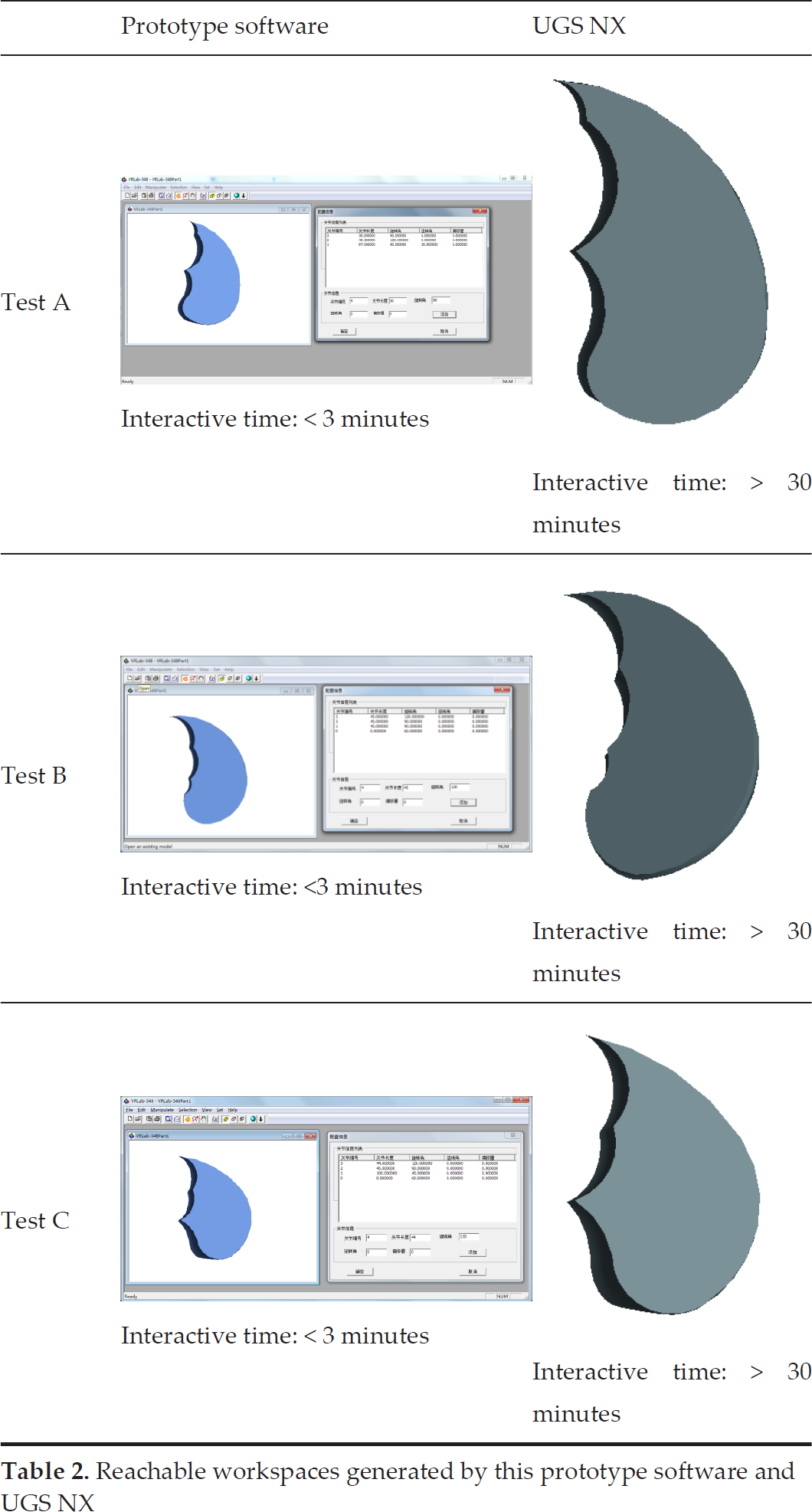

Table 2 shows the 3D reachable workspaces modelled by this prototype software and UGS NX, respectively. It is obvious that the 3D reachable workspaces generated by this prototype software are the same as those generated by UGS NX. This proves that the geometric topology of the reachable workspace of this prototype software is correct, and that the reachable workspace solution is also correct. By adjusting the kinematical parameters, this prototype software can conveniently model the 3D reachable workspaces from Test A to C, and the interactive time is less than three minutes. However, the interactive times for UGS NX to generate each 3D workspace of Test A, B and C were more than half an hour, even for a mechanical engineer, who is skilled at operating UGS NX. This is an obvious advantage of this prototype software, which has a high interactive efficiency.
5.3. Test results and analysis using the importing interface
By using the importing interface, this prototype software can read a 3D model of the dexterous finger. The joint feature-recognition algorithm (in Sect. 4) can automatically recognize the finger joints and calculate the joint distances. After manually inputting the values of the flexion-extension angle and adduction-abduction angle via the dialogue interface, the prototype software then automatically generates the 3D reachable workspace of the dexterous finger
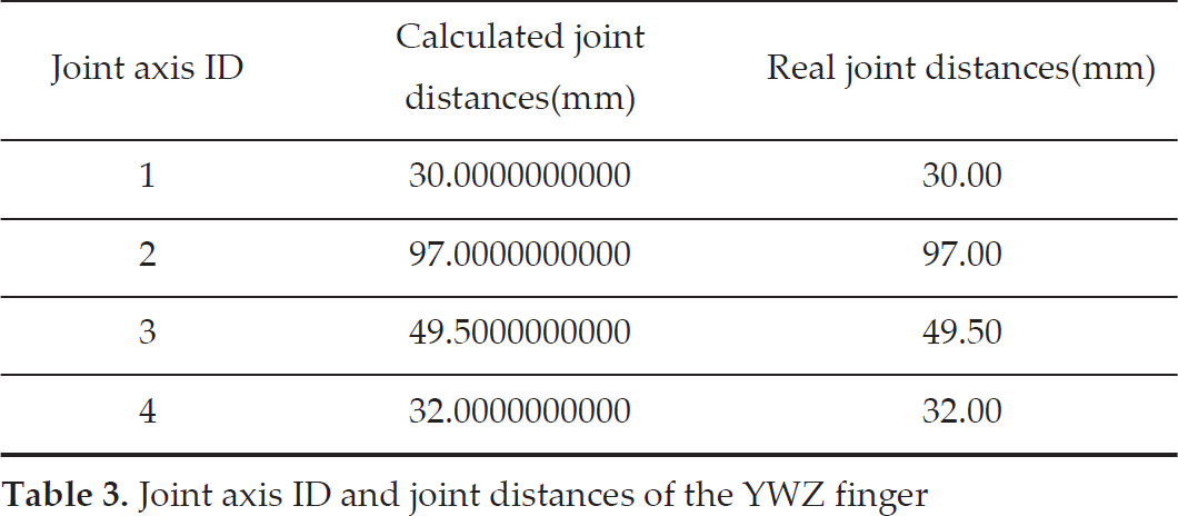
In Figure 5 (a), a dexterous finger 3D model, named the YWZ finger, was imported into the prototype software. After indexing the topology of YWZ finger, as described in Sect. 4.2, we obtained 164 possible joint axes. Then, we obtained 49 possible joint axis sets by clustering, as described in Sect. 4.3.1. We further obtained four exact joint axes with the denoising of joint axes, as described in Sect. 4.3.2. Lastly, we recorded the joint axes' IDs and calculated the joint distances, as described in Sect. 4.4. Table 3 lists the joint feature-recognition results of the YWZ finger.

Reachable workspace of the YWZ dexterous finger generated by this prototype software and UGS NX
Joint axis ID and joint distances of the YWZ finger
Therefore, the prototype software obtains four joints and the joint distances,
Compared with Figure 5(b) and Figure 5(c), the reachable workspace of the YWZ finger modelled using this software is the same as that generated by UGS NX. This also proves that this software can construct a correct reachable workspace of the dexterous finger, and that the joint feature-recognition algorithm (in Sect. 4) can automatically recognize the joint bodies, joint surfaces and joint axes; record the joint axis ID and correctly calculate the joint distances. The recognition accuracy of the joint distances is well guaranteed by the ACIS kernel. Therefore, this prototype software can precisely model the 3D reachable workspace of the dexterous finger.
For the parametric design of the whole dexterous hand, this prototype software can be improved in the future to model each finger-reachable workspace, calculate its reachable workspace volume and analyse the finger-intersection workspace, which is an important feature to evaluate the mechanical design, grasping range and manipulation dexterity of dexterous hands [20].
For example, this software will realize the following functions: 1) to show the certain position of a finger-reachable workspace with reference to the dexterous hand palm, as shown in Figure 6 (a); 2) to calculate the reachable workspace volume, such as the reachable workspace volume of the middle finger of the YWZ dexterous hand, which is

Workspaces of the YWZ dexterous hand
6. Conclusion
It is difficult for researchers to imagine the dexterous-finger reachable workspace, which is beneficial for the grasping plan, motion control and mechanical design of dexterous hands. Although the previous methods, such as the graphic method, numerical method and analytical method, are valid to describe the dexterous finger workspace, they still have some defects. Until now, the commercial CAD modelling software has been inconvenient and unfriendly for modelling the dexterous-finger reachable workspace.
In this paper, we proposed a parametric modelling method to generate the reachable workspace of the dexterous finger, with convenient, automatic and parametric merits. Compared with the Monte Carlo method, this parametric modelling method can obtain more integrated and precise reachable workspaces. With parametric modelling technologies, this method can rapidly generate different dexterous-finger reachable workspaces by adjusting the kinematical parameters of the dexterous fingers. Furthermore, the joint feature-recognition algorithm can automatically find the joint's axis, record the joint axis' ID and calculate the joint distance. We also developed a reachable workspace modelling prototype software for dexterous fingers based on this method. This prototype software can precisely model the reachable workspace of the dexterous finger with high interactive modelling efficiency.
The optimization of the working volume is a fundamental requirement for any industrial robot generally designed as a serial chain whose base is fixed, such as the dexterous finger mechanical structure [21]. In the future, we will develop a workspace volume optimization algorithm to improve the functions of the prototype software, which will also be improved for the parametric design of the whole dexterous hand, as stated in Sect. 5.3, even for underactuated hands.
Footnotes
7. Acknowledgements
This research was supported by Zhejiang Province Public Welfare Project of China (No.2016C33G2060052), Zhejiang Provincial Natural Science Foundation of China (No. LY14F020048), Key Project of the National Natural Science Foundation of China (No.61332017) and National High-Tech Research & Development Program of China (No.2013AA013703). The authors appreciate the anonymous reviewers for valuable comments and suggestions.