
Abstract
This paper proposes an improved algorithm for augmenting the enhanced HDR by utilizing encoder readings to achieve further minimized drift on the yaw-angle estimation of cleaning robots. The primary idea of the proposed approach consists of two phases: 1) classifying the manoeuvre (stop, straight and curving) being carried out using logic as a function of encoder readings; 2) controlling the Attenuator gain, resetting the Binary I-controller and switching Integrator in the enhanced HDR structure, taking into account the identified manoeuvring conditions. The proposed algorithm is applied to a cleaning robot and the experimental data demonstrate the effectiveness of this approach.
1. Introduction
Autonomous cleaning robots have increasingly gained popularity due to their time saving function and for reducing household labour. Developing a low-cost self-localization technology for cleaning robots is one of the most important obstacles in further popularizing these robot products. However, trade-offs exist between cost and quality, and how these factors influence their performance.
Although diverse self-localization technologies such as sensor-based, mark-based and stereo vision-based technologies are being studied [1–3], in general, these systems are expensive [4–6]. On the other hand, the relative localization via yaw-angle estimation with inertial sensors (i.e., low-cost MEMS gyro) holds a considerable advantage in that it is entirely self-contained inside the robot and is easy to accomplish in real-time. Additionally, it results in lower installation and operating costs for the entire system [5,6]. However, as yaw-angle estimation relies on the integration of rate signals from gyros that have relatively large drift errors, unbounded yaw-angle errors can occur, which consequently causes unbounded position errors [7–11].
Recently, studies have been conducted that applied specific techniques to certain systems (e.g., zero-velocity update [ZUPT] and heuristic drift reduction [HDR] for pedestrian navigation) [12]. This presented the possibility of implementing low-cost systems using only gyro sensors. In addition, the enhanced HDR (hereafter referred to as an e-HDR) structure, which adaptively controls the filter gain for updating the gyro drift error more accurately, had been adopted in wheeled vehicles (or mobile robots) [13–17]. However, e-HDR has some shortcomings in certain situations, e.g., 1) when true rates are less than the threshold in the HDR process; 2) when the measured rates are highly contaminated with noise even in the stationary state. In such conditions, the estimated bias is accumulated over time. This shortcoming is primarily due to inability to discriminate its own manoeuvre, as e-HDR utilizes gyro as its sole sensor.
To improve on previous studies involving e-HDR and to achieve further minimized drift on yaw-angle estimation, this paper examines a simple but effective filtering method that augments the e-HDR by utilizing encoder readings. The main idea of the proposed approach consists of two phases; 1) classifying the manoeuvre (stop, straight and curving) being carried out through logic as a function of encoder readings; 2) controlling the Attenuator gain, resetting the Binary I-controller and switching Integrator in the e-HDR structure, taking into account the identified manoeuvring conditions. By applying this strategy, the shortcomings of the e-HDR can be overcome and the drift on yaw-angle estimation can be minimized, regardless of time.
A sensor kit was created based on a MEMS gyro (MPU6050, InvenSense Co. [18]) and a microcontroller (ATmega328, Atmel Co. [19]). The proposed algorithm was embedded into the kit and its effectiveness demonstrated through precise rate-table tests and actual manoeuvring tests on a commercial cleaning robot.
2. Heuristic Drift Reduction (HDR) Filter
2.1. The pure HDR filter
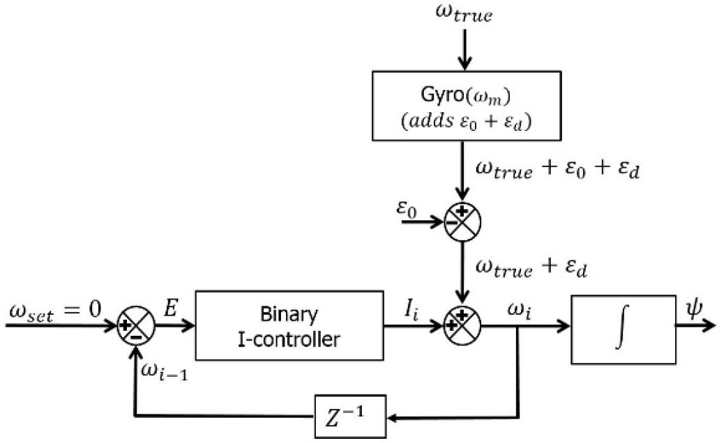
The gyro's bias drifts are a major cause of performance degradation due to the accumulation of integration errors during yaw-angle (ψ) estimations. To estimate and compensate for bias drifts, HDR in the form of closed loop control systems were presented [12]. A block diagram of the filters are shown in Fig. 1
Block diagram of pure HDR filters
Block diagram of e-HDR filters
The rate of rotation measurement (ωm) including error factors and the estimated rate (ωi) are as follows:

where
The fixed bias

Meanwhile, to remove the bias drift element (
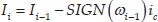
where ic is a fixed increment and
Theoretically, in a steady state, because of the I-controller, E in Fig. 1 will eventually be zero, which implies that the control signal I will track (but with an opposite sign) slow changes of εd with no offset. That is,
2.2. The e-HDR filter
e-HDR gains further performance enhancement during motion, specifically for the mobile vehicle, compared to the pure HDR, through the addition of an ‘attenuator’. That is, the estimated bias drift (Ii) can be applied differently depending on the size of
Attenuator gain (Ai) is controlled by Eq. 4, shown below.

where
The entire e-HDR algorithm can now be implemented by:

When compared to the estimation equation for pure HDRs (Eq. 3), it can be seen that bias drifts can be more effectively estimated with attenuator gain (Ai), considering the manoeuvring conditions. However, to estimate the bias drift using e-HDR, the cleaning robot must stop or move straight (
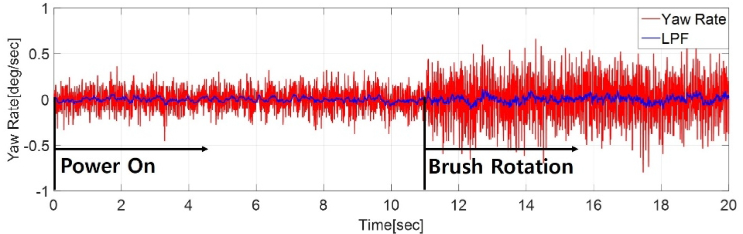
Raw gyro outputs in stationary situations with brush rotations
3. Augmentation of e-HDR Utilizing Encoder
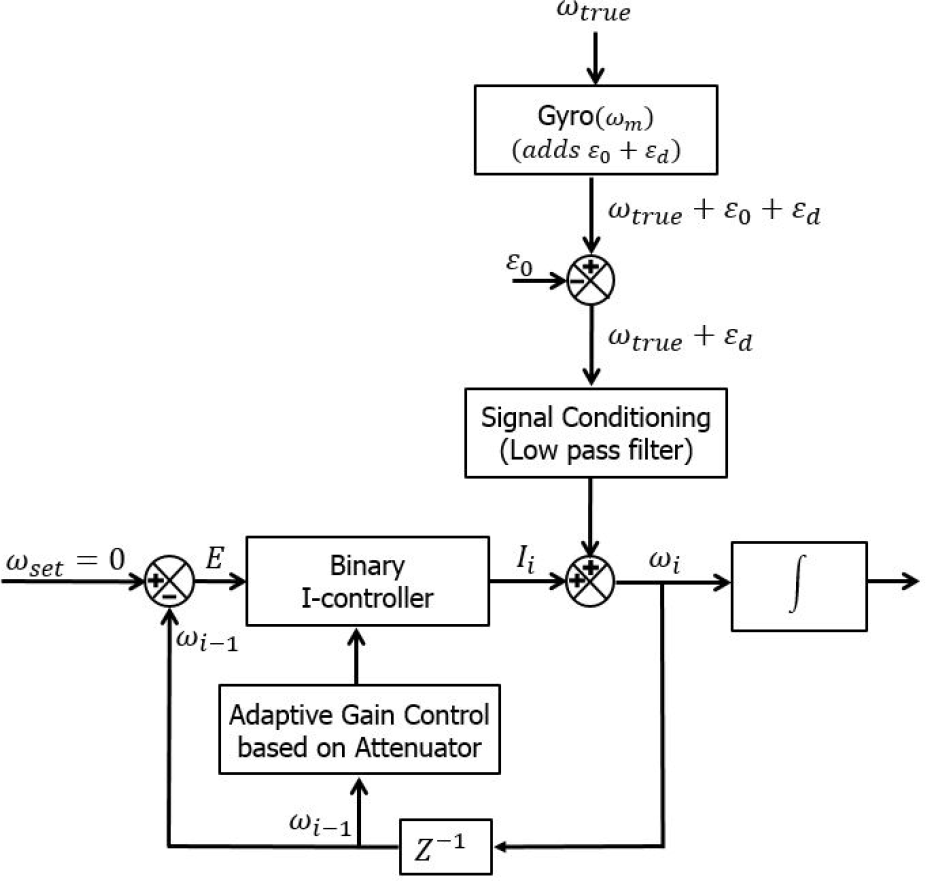
As reviewed earlier, e-HDR has some shortcomings in certain situations, e.g., when: 1) true rates are less than the threshold; 2) the measured rates are highly contaminated with noise even in the stationary condition. In this section, an improved algorithm is presented that augments the e-HDR by utilizing encoder readings. The major concept of the proposed algorithm consists of two phases: 1) classifying the manoeuvre (stop, straight and curving) being carried out through logic as a function of encoder readings; 2) controlling the Attenuator gain, resetting Binary I-controller and switching Integrator in the e-HDR structure, taking into account the identified manoeuvring conditions. A full conceptual block diagram for the proposed augmentation of an e-HDR-utilizing encoder is shown in Fig. 4.

A block diagram of the augmentation of the e-HDR-utilizing encoder
3.1. Classifying manoeuvres
In this study, encoders were used to discriminate the cleaning robot's manoeuvres. Even though diverse error factors generally exist in low-grade encoders installed in cleaning robots, identifying the cleaning robot's manoeuvres such as stopping, driving straight and turning can be considered valid. Additionally, the discrimination of such manoeuvres via encoder readings is more apparent than those via gyros, as shown in Table 1 [5].
Discrimination effectiveness for mobile robot manoeuvres

3.2. Manoeuvring discrimination logic via encoders
The logic for manoeuvring discrimination through encoders is shown in Table 2, where
Definition of manoeuvring discrimination functions through encoders

3.3. Refining the attenuator
Attenuator gain (Ai) control via the manoeuvring discrimination logic indicated above is shown in Eq. 6 below:

Through this refined attenuator, which utilizes encoder readings, the manoeuvring conditions with angular rates lower than the threshold are considered as swaying motion, i.e., unlikely e-HDR.
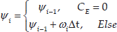
3.4. Resetting I-controller
The purpose of resetting the I-controller is to nullify the accumulated error in estimated bias drift (
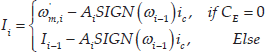
3.5. Switching logic for integration
During operation of the cleaning robot, yaw-angles do not change in the stationary condition; thus, the integration process in such a condition is set to halt in order to further minimize the accumulation of integration errors. Therefore, integration is performed only when
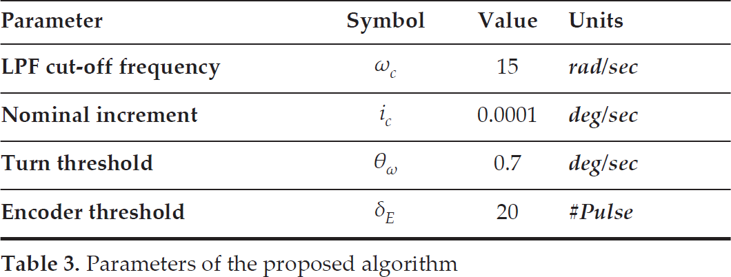
The set parameters for implementing the proposed algorithm are shown in Table 3.
Parameters of the proposed algorithm
4. Experimental Results
For experimental verification, a sensor kit (uploaded with the proposed algorithm estimation filter) that satisfied the specifications of the electric interface and the size of the commercial cleaning robot (VR20H9050UW, Samsung) was designed and fabricated in-house (see Table 4). The MCU (micro controller unit) of the inertial sensor kit was based on ATmega328 (Atmel Co.) and the MPU6050 z-axis gyro sensor (InvenSense Co.) was adopted as the MEMS gyro. An RB-35GM (D&J WITH Co.), installed in the cleaning robot, was used as an encoder.
Specifications of the yaw-angle estimation sensor kit

4.1. Precise rate table test
To verify the effectiveness of the proposed algorithm compared to e-HDR in certain situations (when the input rate is less than the threshold (

Precise rate table test and sensor kit
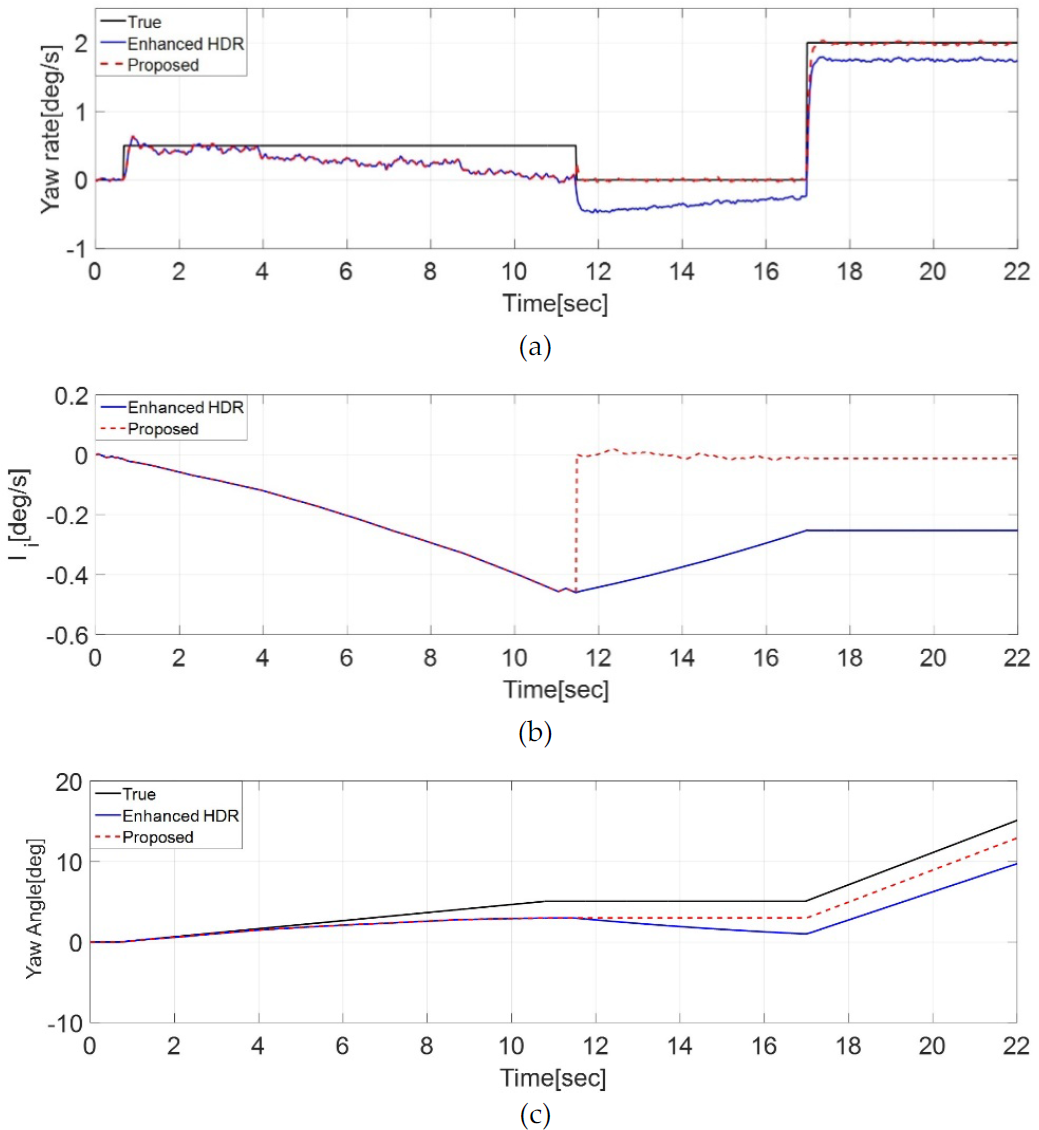
Comparisons between the proposed algorithm and e-HDR: (a) yaw rate; (b) estimated bias; (c) yaw-angle
4.2. Manoeuvring test
For verification through actual manoeuvring tests, the sensor kit was installed on a commercial cleaning robot (VR20H9050UW, Samsung). Manoeuvring tests consisting of driving straight and turning were repeatedly conducted for approximately 300 sec on the 3 m× 1 m track on which the reference equipment motion capture system (Raptor-4, Motion Analysis Co. [20]) was installed (see Fig. 7). Sensor kit data and reference equipment data were obtained via Bluetooth and Ethernet, respectively, at 50 Hz (see Fig. 8).
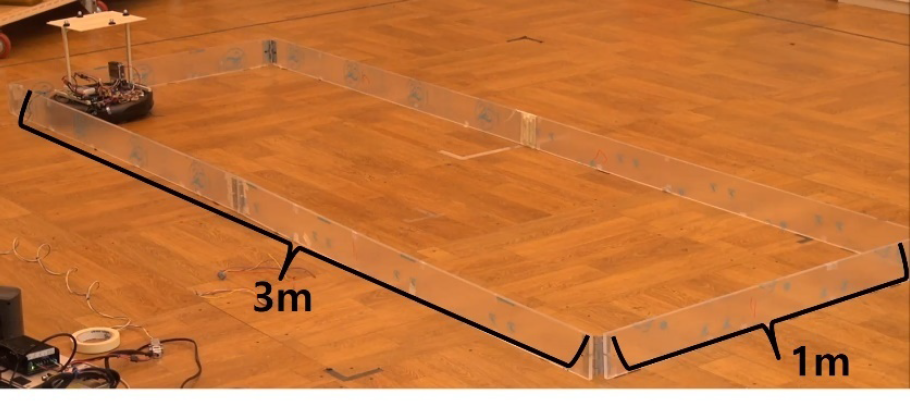
Test arena

Block diagram of sensor kit and data acquisition
Fig. 9(a) shows the X-Y trajectory for when the robot is in auto cleaning mode. The cleaning robot divides the 3m× 1 m track into section ‘A’ and ‘B’, and conducts the cleaning process (wall following, then a zig-zag pattern) separately. The black, dashed line represents wall following, while the red line represents movement via the zig-zag pattern. Fig. 9(b) and (c) show the trajectory X and Y versus time, respectively.

Trajectory versus time: (a) X-Y; (b) X vs. T; (c) Y vs. t
The results of the estimated yaw-angle for both proposed algorithm and e-HDR can be seen in Fig. 10. Fig. 10(b) and (c) show that while the e-HDR showed an increase in errors over time (

Results of the manoeuvring tests: (a) yaw-angle; (b) enlarged (276~300s); (c) error
Quantitative experimental results

5. Conclusion
This paper proposed an improved algorithm that augments the e-HDR by utilizing encoder readings to achieve further minimized drift on the yaw-angle estimation of cleaning robots. The primary idea of the proposed approach consisted of two phases: 1) classifying the manoeuvre (stop, straight and curving) being carried out through logic as a function of encoder readings; 2) controlling the Attenuator gain, resetting Binary I-controller and switching Integrator in the e-HDR structure, taking into account the identified manoeuvring conditions. The proposed algorithm was implemented in a sensor kit, which was self-fabricated for this study and its effectiveness was demonstrated through precise rate-table tests and actual manoeuvring tests on a commercial cleaning robot. By applying this strategy, the shortcomings of the e-HDR can be overcome and the drift on yaw-angle estimation can be well-bounded, regardless of time and minimized (
Footnotes
6. Acknowledgements
This work (Grants No.C0333549) was supported by Business for Cooperative R&D between Industry, Academy, and Research Institute, fund in the Korea Small and Medium Business Administration in 2015.