
Abstract
In this contribution, several strategies of force control have been proposed to be implemented and evaluated in ROBOCLIMBER, a quadruped robot of large dimensions. A first group of strategies proposed in this paper is based on impedance control, which is intended to adapt the foot-ground contact forces according to the experimentally specified damping ratio and the undamped natural frequency. A second control strategy of interest for many practical cases is called the parallel force/position control, which has one inner loop position control and two external control loops, one of force and another of position. A third group of control strategies is the posture stabilization for ROBOCLIMBER using the feedback of the ZMP calculation and the position of its legs. Finally, a control strategy for the control of a quasi-static gait using ZMP feedback is proposed and tested by simulation.
Keywords
1. Introduction
In industrial applications of robot technology, several strategies of force control have been employed. In order to carry out these strategies, various kinds of force and torque sensors are used. A classic example is when industrial robots (robot manipulators) are intended to work in contact with the unstructured environment. Then the main control objective is to regulate the force and torque that the robot manipulator exerts when it comes in contact with its environment, while controlling the position in those directions in which the environment does not impose restrictions of movement [1, 2].
Some works related to the force measurement on the end effector of a manipulator (e.g., a gripper, tool centre point, etc.) can be found in [3–5]. Other results regarding measurements on different parts of robots (e.g., legs, feet, etc.) can be found in [6–11]. Furthermore, good reviews of the literature have also been published in [12–15].
Today, the use of different types of sensors in automation and robotic systems makes it possible for these powerful tools to carry out more complex tasks in unstructured and/or partially unknown environments. For example, sensors that can measure force, torque, or pressure usually contain elastic elements that convert the mechanical magnitude into a deflection or strain [16, 17]. There is a wide variety of commercially available sensors that are built on different physical principles for measuring these kinds of signals, e.g., load cells, torque cells, piezoresistive sensors, strain gauges, pressure sensors and combined sensors, among others. Strain gauges are employed to experimentally evaluate the force control designs proposed in this paper [4]. With this intention, the mechanical design of the ROBOCLIMBER feet was carried out to install this sensor type.
The designs of the various kinds of robot described in [18–26] and the application of legged robots (climbing and walking) are the subject of extensive and growing interest to the scientific community [27–32]. The gait of legged robots features the opening and closing by themselves of several kinematic chains on the terrain, allowing multiple foot-ground contacts along their displacement [30, 33], which result in changeable patterns of reaction forces that determine robot stability. For this reason, several studies have been carried out on the force control applied in walking robots, using various types of force/torque sensors according to the applications performed. Force control can be used to avoid the risk of feet slippage, regulate force distribution, carry out compliant robot motion, reduce energy loss, identify mechanical properties and, consequently, spread robot work capabilities [6, 34–35].
This article discusses several strategies of force control implemented in a legged robot of large dimensions. The proposed methodology is based on force-sensing requirements considering the stage of the design of the robot. The force-sensing is acquired from embedded force sensors within the mechanical structure of the robot's feet, avoiding the use of expensive and bulky commercial sensors [10, 36].
ROBOCLIMBER is the test case of this work [37]. This machine is a heavy, quadruped, climbing and walking robot with weighty legs, hydraulically actuated, which is capable of carrying out heavy-duty drilling operations in order to perform consolidation and monitoring tasks on rocky mountainsides. A previous control strategy using the built-in force-sensing capability implemented in the ROBOCLIMBER can be seen in [10]. It performs detection of obstacles/levels when the robot leg performs vertical movements to approach the soil. The first force control strategy, described in this work, is called impedance control. In this strategy, a specified dynamic behaviour between each leg and the soil interaction is imposed. The dynamic impedances are specified in the control algorithm for the legs to interact with the soil according to the desired behaviour. Another force control strategy presented in this paper is the parallel position/force control implemented in the ROBOCLIMBER. The controller consists of one internal loop of position and two external loops, one of them of position and the other one of force. Both references, of position and force, make the legs of the robot interact with the soil with good compliance. Additionally, a force control strategy for the attitude stabilization of the ROBOCLIMBER is also presented in this article. This strategy is very important for the attitude stabilization of the machine when it is performing consolidation of the rocky slopes. Finally, in this paper an approach to the posture control of the ROBOCLIMBER for a quasi-static gait using the Zero-Moment Point (ZMP) feedback is presented. The ZMP data and the centre of gravity (CoG) are acquired/computed in real time in order to reduce the error between them. The dynamic error between the positions of the ZMP and the CoG is considered. Promising simulation results are obtained with these real data.
2. General description of ROBOCLIMBER
ROBOCLIMBER is a quadruped robot of large dimensions that can move on soil (walking robot) and that can also climb the slopes of the mountains with the help of two steel ropes secured at the top of the mountain (climbing robot) [37]. The development of this robot was funded by the EC under two Growth/Craft projects, where the objective was to develop a tele-operated service robotic system to perform consolidation and monitoring tasks on rocky slopes.
ROBOCLIMBER can carry the drilling equipment and other auxiliary elements on-board when it is performing consolidation tasks on mountain slopes. This robot is actuated by hydraulic cylinders and controlled with a high-level protocol from a remote location without the need for on-board operators [38]. The mechanical structure of this machine is supported by four legs, where each leg has three degrees of freedom in a cylindrical configuration (one rotational joint and two prismatic joints) [10–11]. Each leg of the robot is capable of bearing loads of more than 15,000 N; therefore, this machine can bear and move a mass of 4,000 kg (its own structure, the drilling unit, drilling rods and other auxiliary equipment) with relative ease [11].
For the development of consolidation works on uneven mountains, ROBOCLIMBER must be hung up by two steel ropes secured at the top of the mountain and two special hydraulically driven devices called rope tensioning appliances installed at the front of the robot to pull itself up. With this concept, the robot is able to climb mountain slopes with inclinations ranging from 30º to close to 90º [10–11]. The displacement of the robot on the mountainside is obtained by the simultaneous coordination (real time, on-board control) of the hydraulic rope tensioning appliances and the appropriate gait sequence generation, resulting in successful climbing [38]. Nevertheless, the ROBOCLIMBER can walk on horizontal surfaces, which is the subject of this paper, although the final purpose of the force control strategies presented below, beyond the scope of this paper, was to transfer the knowledge acquired during this work, in order to apply it to the robot when it is working on the mountain slopes. One defined goal was to dampen vibrations on the robot when it is performing drilling operations on rocky mountainsides.
Figure 1 shows the ROBOCLIMBER, a four-legged hydraulically actuated robot, used for the experimental part of this contribution. The main parts are shown. In this figure it is possible to notice some data regarding the robot dimensions. In addition to the body structure (robot frame) and legs of the robot, the control system, the hydraulic power unit and the electrical power generator are also shown.
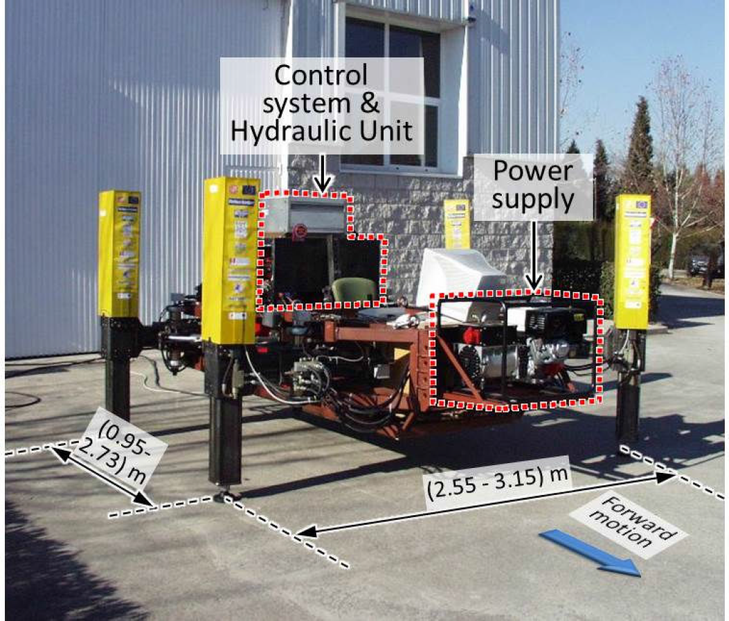
ROBOCLIMBER, four-legged hydraulically actuated robot at CAR (CSIC-UPM) premises, Spain. Main parts are shown.
3. Force control strategies
The ROBOCLIMBER uses hydraulic actuators to perform its movements; thus the control system mainly comprises two cascaded stages. The first stage is composed of control subsystems of the proportional hydraulic valves, which control the speed of the hydraulic cylinders. The second stage is composed of position controllers, which are based on the position feedback measured by means of linear and rotational encoders, to control the position of the robot joints [30]. Additionally, another control loop has been implemented on the robot, which is the force feedback loop to implement several strategies of force control on the ROBOCLIMBER. When any strategy of force control is implemented on the robot, the behaviour of its legs is like a virtual spring-damper. Figure 2 serves to illustrate this concept.
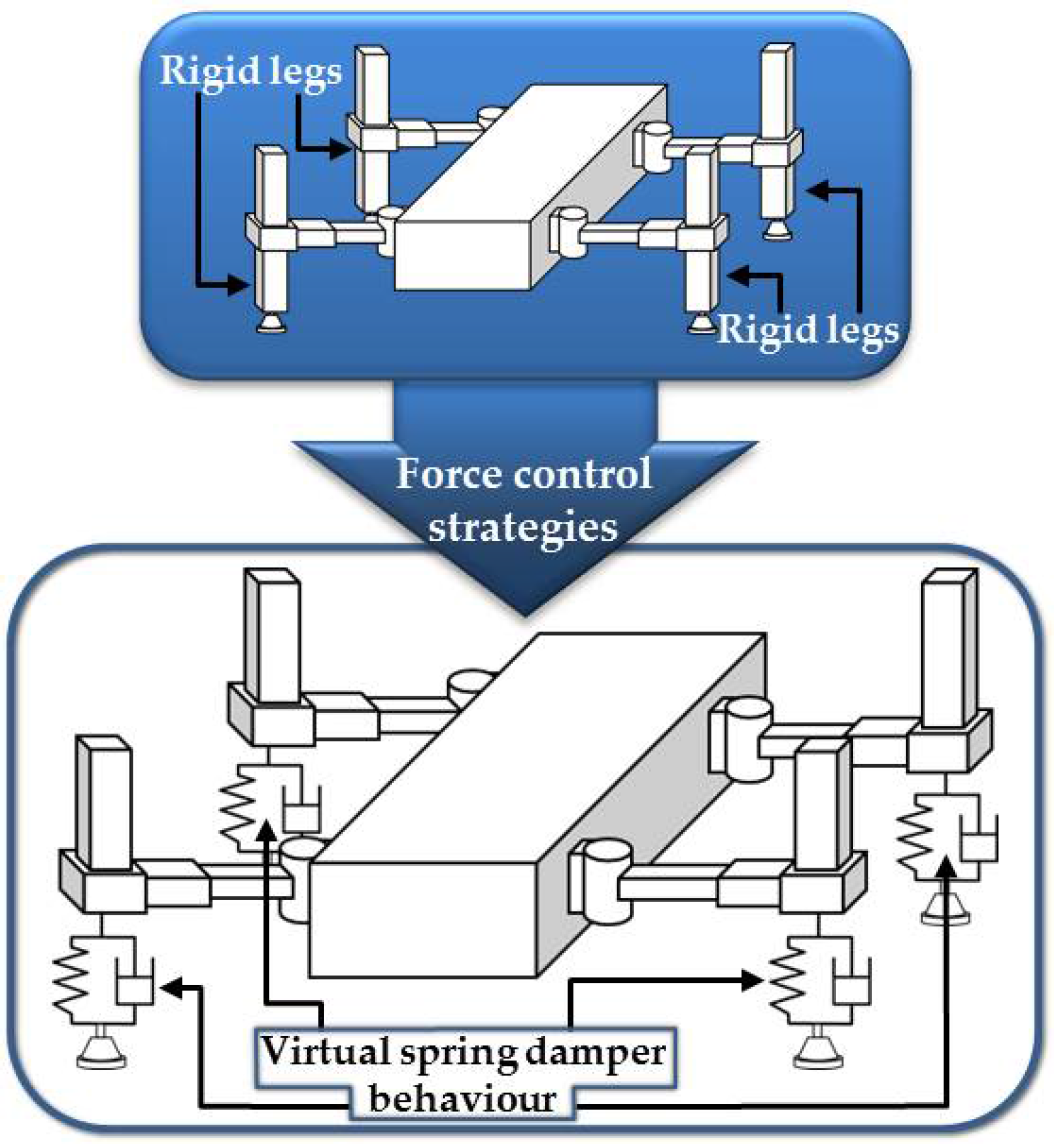
Concept of the force control effect on ROBOCLIMBER
In this paper, several force control strategies have been implemented in order to carry out some gaits on several soil types, both indoors and outdoors. These experiments included posture stabilization when a redistribution of the force on each leg was carried out, while the robot executed a quasi-static gait on several terrains. Furthermore, over flat terrain, the ZMP was computed with the force measurement in each leg, with the aim of reducing the distance between itself and the CoG and, therefore, increasing the stability margin during the gait.
These control strategies include force feedback loops, which were implemented and evaluated experimentally on the ROBOCLIMBER. A first strategy proposed in this work is based on impedance control, which is intended to accommodate the foot-ground contact forces according to given specifications of damping, and undamped natural frequency. A second strategy of interest in many practical cases is called parallel force/position control, which is presented in this section. Finally, in this paper two different strategies to control the posture of the ROBOCLIMBER based on the ZMP computation are proposed. In one of them, the walking machine controls its posture in a static position when it is subjected to perturbations. In the other one, some simulation results are presented when the robot performs a quasi-static gait. In this case the real data acquired during the gait, which is a two-phase discontinuous gait, are used.
In previous experiments [10], the high sensibility of force measurement system has been presented, considering the bulky mass of the robot. Additionally, the reliability of the control system has exhibited an excellent responsiveness of the feet when they are in contact with soils of several types of stiffness. This demonstrates that the robot is similar in behaviour to a spring with different stiffness characteristics, depending on the force control strategy implemented on it (see the concept in Figure 2).
3.1. Impedance control
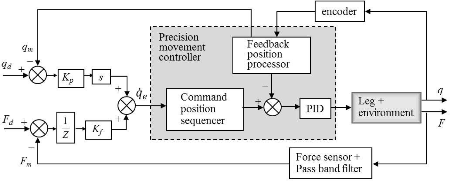
Impedance control is a control strategy that provides very interesting results. It is a method that has been proposed by some researchers in order to allow the compliance of the robot structure to minimize the forces and torques of the links and joints, respectively, when it is interacting with the environment (especially in the case of robotic manipulators) [39–42]. Impedance control has been proposed for improving walking robots' behaviour by several authors [30, 34–35, 43]. For this purpose, the desired impedance that the robot should have in its interaction with the environment must be specified. Figure 3 shows the block diagram of the impedance control proposed to be implemented on each leg of the ROBOCLIMBER.
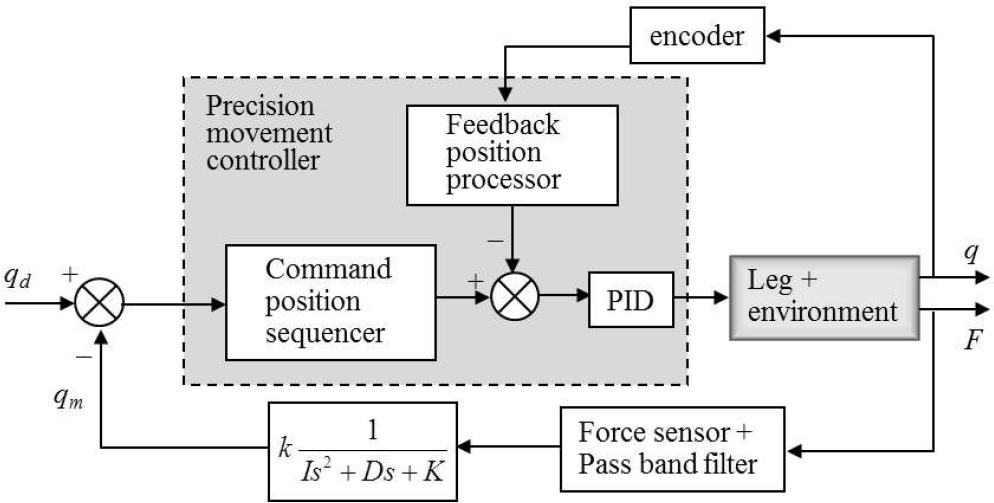
Impedance controller block diagram
This control strategy has an external control loop of force, which is converted to a measured position set-point
Initially, the desired impedance must be specified by a transfer function of second order, which is suitable for this case because the dynamic performance of the leg is of the same order. In this control system, set-points of the desired motion trajectory are presented and in this way the dynamic relationship between the interaction force with the environment and the position error are regulated.
The impedance controller (see Figure 3) was implemented in the prismatic joints of the legs, which are orthogonal to the robot's frontal plane, i.e., the link where each foot is implemented. Several dynamic characteristics were specified by implementing various mechanical impedances in order to observe the behaviour of foot-ground contact.
The purpose is to emphasize how the proposed impedance controller is able to regulate the dynamic relationship between the interaction force with the soil and the position error when a leg trajectory is established. Since the constants that comprise the impedance controller are relatively low, the accuracy of positioning is not high, but the foot-ground interaction is carried out with relatively small forces. This strategy is convenient because if the robot is able to interact with its environment with small forces, then it will be able to interact with larger forces. Therefore, with this strategy the minimum force limits of foot-ground contact are being sought, which the robot is able to work.
In order to carry out the experiments, it is necessary to know the step response of the contact force of the foot with the soil. The control algorithm is implemented in each one of the legs independently.
Specifically within the initial conditions for impedance controller design, in each case, it is necessary to evaluate the natural frequency,
The values of the parameters that define the mechanical impedance are low, which means that the end position is not achievable rapidly. Moreover, the energy dissipation in the system is not high, because the described system is underdamped. Obviously, the mechanical impedance parameters may be modified by means of greater values, so that responses to interaction with the environment would be most appropriate. However, low values in the mechanical impedance parameters were used to perform, with some dexterity, the planned experiments. This is because, otherwise, it would be very difficult to carry out the same experiments. The diagram in Figure 4 shows the experiment carried out in three steps.

Scheme of the experiment to evaluate the impedance controller. Fd, desired force; Zd, desired impedance.
The measurement of force is converted to position commands by using the discrete Z-transform of the required impedance and implementing the corresponding time difference equations in the control system.
A desired set-point of position is established to simulate the step response of force when there is foot-ground contact. Figure 5 shows the position signal of leg 2 and its interaction force with the soil during the test. Three position steps are observed in the first plot of Figure 5, and the three position steps are relatively stable, without considering the interval 15s < t < 33s. This is because the foot-ground interaction was subject to external perturbations in order to evaluate its behaviour. During this interval, the leg position oscillated about the set position (q m = −383 mm), trying to adapt to the ground while being subjected to considerable perturbations.
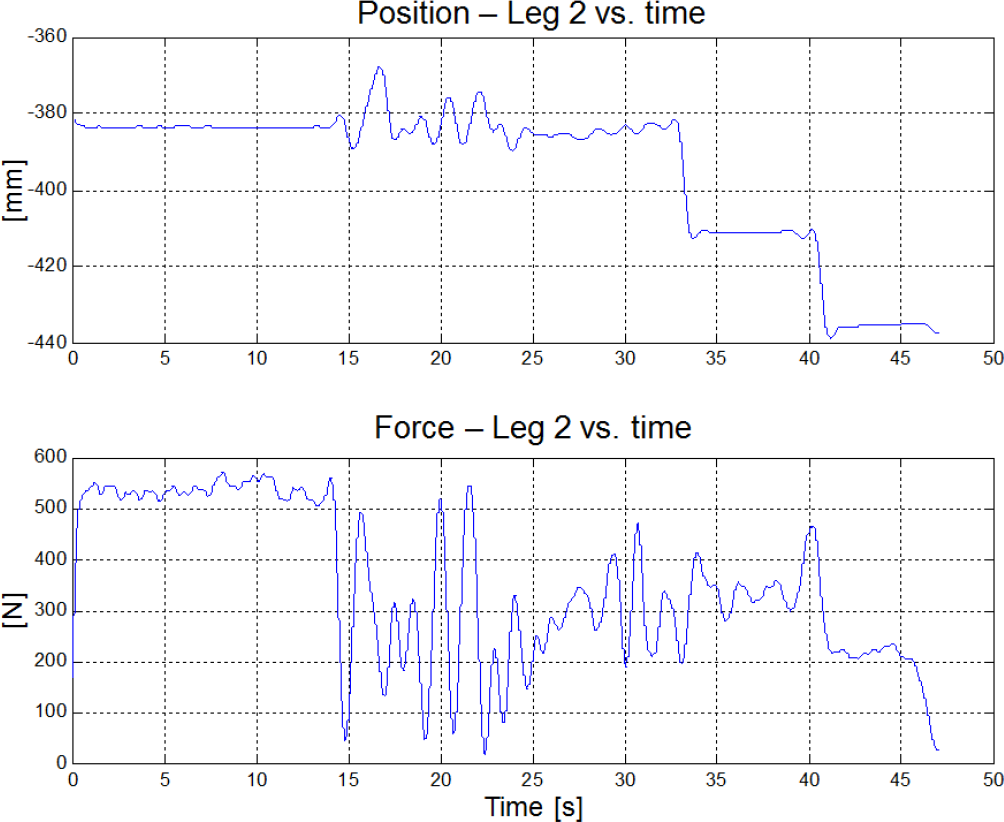
Foot-ground contact response of leg 2 of the ROBOCLIMBER using the impedance controller
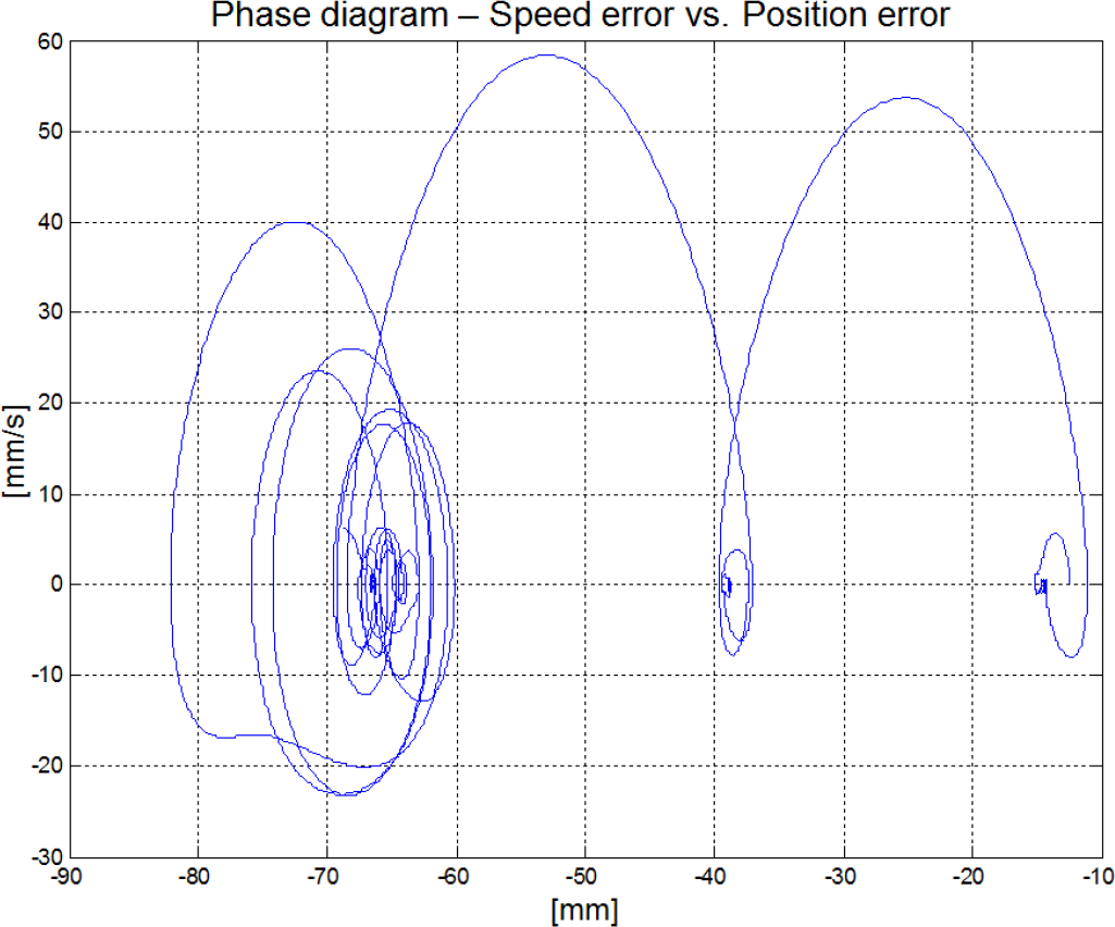
Figure 6 shows the dynamic behaviour of the position error in leg 2 of the robot. The three steps established in the experiment are clearly observed. Since the speed error is zero (when the leg makes contact with one step), the stability of the system is demonstrated, despite the parameters of the mechanical impedance being low. In the first level it can be noted that there is an external disturbance and the controller tries to stabilize the system. During the transition from one step to another, the speed error increases considerably (up to the maximum speed at which the prismatic joint is moved) until the foot makes contact with the next level. As indicated above, the constants that comprise the desired impedance used for this experiment were low, but sufficient to get acceptable responses. Therefore, it must be mentioned that, by adjusting these constants to other high values (or corresponding values depending on the task), a high accuracy in the positioning of the legs will be performed and with high energy dissipation according to the characteristics of the ROBOCLIMBER.
Dynamic behaviour of the position error of leg 2
3.2. Parallel force/position control
Apart from the concept of impedance control, which was introduced in the previous subsection, there is also another impedance control concept based on motion control, where movement control is implemented by means of an inner position loop that establishes settings to motion commands.
This controller also has two external loops, one with a low stiffness position and another to generate adjustments to the reference positions, which depend on the interaction force with the environment. This adjustment of the reference positions is carried out through the transformation of the forces by means of the desired impedance. The result is a parallel force/position controller (see Figure 7). This is because the control strategy is formulated simultaneously, with position and force references. Thus, in the directions in which the movement of the leg is restricted, forces are generated large enough so that the force controller has dominance over the position controller. However, if there are no interaction forces, or they are negligible, the position controller dominates.
Parallel force/position controller block diagram
The commands of position and force are converted to speed commands, which are introduced to the precision movement controller. This controller uses the speed commands and the position signals from the inner loop of position in order to control the motion of the leg according to the control strategy established to interact with its environment. Thus, the control law is defined by the following equation:

In equation (1) the force error is converted to speed set-points through the impedance Z, specified in the algorithm, and the position error is converted to speed set-points through s⋅Kp.
The parallel force/position controller proposed in this paper (see Figure 7) was implemented in the articular space of all four robot legs. This is because the robot legs have a cylindrical configuration and the force signal is measured only on the vertical axis of each leg.
Figure 8 shows a schematic diagram that illustrates the concept followed in the experimentation and a photographic sequence of the experiment. The conceptualization of the experiment is as follows: first, the robot is in its equilibrium state (1); in (2) one external force is applied onto the robot; therefore the robot was moved down until it reached position (3), which is a position proportional to the applied force. Without external force the robot returned back to its initial position (4). In snapshots (5) and (6), another external force was applied and removed, respectively.

Experimentation using the parallel force/position controller. (a) Scheme of the concept used in the experiment. (b) Photographic sequence of the experimentation.
For this experiment, the force error is converted to speed command through the desired impedance and a proportional action coefficient (K f ), experimentally adjusted (see Figure 7). In most of the experiments, the mechanical impedance approaches stiffness, i.e., the inertia constant and the damping constant are small. The position error in the external loop is adjusted with constants of proportionality, which are experimentally evaluated to interact properly with the measured forces (converted to speed variables). In this case, the resultant speed set-points are input to the precision movement controller. The objective is to have a compliance control of the legs with the soil, “tricking” it to the position microcontroller with speed commands, which are functions of the leg positioning and the foot-ground contact forces (please refer to Figure 7).
According to the actual force distribution on the robot legs, the desired forces for the controller are defined (F d , force vector set point). The desired forces are different for each leg, since the mass of the robot is not homogeneously distributed. In this experiment, the stiffness matrix constants of impedance Z are defined with relatively low values in order to observe more easily the behaviour of the posture of the robot when an external force is applied. With these low values of the stiffness matrix, a highly sensitive behaviour of the robot is reached and for this reason it is relatively easy to carry out the experiments applying low loads (simply pushing down with the hands, as shown in Figure 8), which otherwise would require heavier loads. The interaction forces with the soil (measured forces) and the displacement of the robot legs (measured positions along the z-axis) can be appreciated in Figure 9 and Figure 10, respectively.

Force perception in each leg of the ROBOCLIMBER during one of the tests with the parallel force/position controller
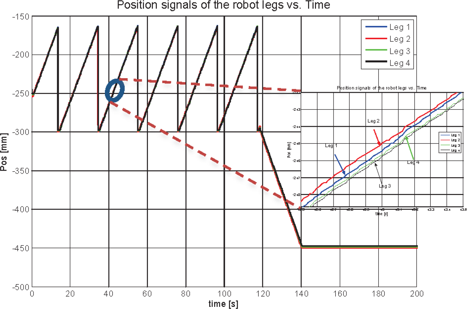
Position signals of the legs of the ROBOCLIMBER during one of the tests with the parallel force/position controller
The desired position set-point is the same for each leg (
The window to the right in Figure 10 shows the position signals of the legs, which are extended for one second, in the interval of
3.3. Posture stabilization for the ROBOCLIMBER using ZMP feedback
Controlling robot posture is an important problem when it is under the influence of external perturbations, or simply when the robot moves over any type of terrain (uneven or not). Some related works on robot posture control, including biped robots, quadrupeds and hexapods, can be seen in [46–49]. In the ROBOCLIMBER case, external perturbation sources consist of the variation of its payload (frequent in practice), the drilling tasks, and its leg movement, which in this case, unlike with other robots, is not negligible. These external perturbations may be caused by the ZMP displacement from its desired zone, apart from the vibrations caused by the performance of a task. Considering the ZMP displacement, in order to control the robot posture (on a horizontal soil), it is necessary to calculate the ZMP in real time; first when the robot is statically stable and also when it is subjected to external disturbances. When external perturbations occur, the ZMP is moved out of its predefined security zone, which is considered the maximum stability zone. Therefore, the robot must accommodate its posture, so that the ZMP returns back to its established zone. For this purpose, the control scheme shown in Figure 11 is proposed.

Posture controller for the ROBOCLIMBER using ZMP feedback
As with the other control strategies proposed, there is an inner position loop of high stiffness to control the hydraulic actuators in a proper way. In this case, apart from having an external position loop to control leg displacement (along the z-axis), an external loop for setting the ZMP is considered. For this purpose, the position data of the robot joints on the frontal plane and the measurements of the reaction forces on the legs are considered in order to obtain the “measured ZMP” (see equations (2) and (3)) [10, 30].
This control strategy is performed in the articular space. The position control external loop carries out only the position feedback of the prismatic joints orthogonal to the frontal plane of the robot. In addition, the external loop for the ZMP adjustment relates only to the forces and positions expressed in the articular space with speed commands in the articular space (z-axis). The control law introduces a speed command to the position internal controller for the stabilization of the ZMP, as presented in equation (4).
The desired ZMP is set as an extended point of the centre of pressure of the robot, when it has a statically stable posture and when the positions of the legs form a symmetrical polygon around the support plane.
This control strategy causes the control algorithm to work in the prismatic articular space orthogonal to the frontal plane of the robot. The ZMP must be calculated constantly in order to keep it within the area established as the ZMP stability zone. For this, equation (5) should be considered. The


where,


where,
The robot is statically stable on the soil (flat surface assumption) as an initial condition of the experiment. The robot is held up on its four legs, whose displacement is 500 mm above the soil. The force distribution on the robot legs is stable. Subsequently, a perturbation force is introduced on the robot front, so that the ZMP is moved out of the stability zone, causing the robot to carry out a pitch motion. In this case, the front legs reduce their position and the rear legs increase their position, with respect to the axis orthogonal to the robot body. When this occurs, the legs are moved actively in correspondence to the ZMP movement. When the disturbance tends towards zero, the controller attempts to return the ZMP to its stability zone. In order to accomplish this, the robot accommodates its body by adjusting the position of its legs (the control strategy considers the previous position of the leg during the return to the stability posture), so that it adopts a posture of stability again. Figure 12 shows a schematic diagram that illustrates the concept of posture stabilization and a photographic sequence of the experimental evaluation.

Experimentation using the posture stabilization controller. (a) Scheme of the concept used in the experiment. (b) Photographic sequence of the experimentation.
With this intention, the robot can acquire a significantly unstable posture and the ZMP external loop becomes very sensitive deliberately, so that it can be displaced relatively easily. The purpose is to determine the capacity of action of the control algorithm to return the robot to a stability posture, after inducing a disturbance on it during the experimentation (see Figure 12).
Figures 13 and 14 respectively show the displacement of the robot legs and the forces on them during the implementation of the experiment. Each posture stabilization interval on the robot is marked in this figure with Roman numerals I, II and III. It can be noted that the front legs (legs 1 and 2) are retracted and the hind legs (legs 3 and 4) are protracted, so that the robot executes a pitch motion. Following each perturbation, the robot returns to its position of stability.

Vertical displacement of the robot legs during the experiment

Force measurement in each leg of the ROBOCLIMBER during the posture stabilization experimentation
It is important to note that in each case the ZMP returns to the equilibrium zone, so that the robot legs again reach the initial force distribution (the same as before the perturbations were applied). That is, the contact force with the ground on each robot leg is the same after the disturbance on the ZMP caused by the externally applied force has vanished. This can be noticed in Figure 14, observing the force signal segments marked with Roman numerals I, II and III. This is a very important result, since by controlling the ZMP within a narrow band (ZMP stability zone), the previous stable force distribution is reached. The force distribution after the perturbation is the same as (or at least very close to) the previous force distribution.
Figure 15 shows the behaviour of the ZMP on the sagittal plane, because at that plane the robot performs the pitch motion. The ZMP displacement on the transverse plane is hardly appreciable. In Figure 15, the ZMP calibrated is marked with a small yellow circle and the letter “I” within a green frame indicates the initial position of the ZMP in this experiment. Furthermore, the same figure shows that the ZMP reaches the stability zone after each perturbation (in II and III marked in Figure 13), making the distribution of forces on the robot legs similar when the robot adopts a statically stable attitude. In this experiment, two different perturbations were applied on the robot and consequently two different dynamic responses were obtained. The first one is plotted in blue in Figure 15, in which it occurs between marks I and II (see Figures 13–14). The second, in red, is between marks II and III. Therefore, it is clearly noted that the control algorithm places the ZMP, quickly, within the stability zone, after the disturbance inputs.

Dynamic response of the ZMP in the sagittal plane of the ROBOCLIMBER during the experiment
3.4. ROBOCLIMBER control for a quasi-static gait using ZMP feedback
In this case it is desirable for the ZMP to follow the centre of gravity of the robot when a gait is executed. For this, the ZMP is computed in real time, avoiding (as much as possible) any interference caused by uncertainties in force measurement, which can happen when there are slippages or at the time in which a transient phenomenon of the force distribution has occurred. In this control strategy the displacement of the legs along the vertical axis is modified, so that the ZMP approximates to the centre of gravity of the robot. In Figure 16 the control diagram of this strategy is shown.

Control system scheme for the stabilization of the ROBOCLIMBER during a quasi-static gait
The geometric centre of the robot in the frontal plane is defined as the origin of the reference system. This is because the forces measured are orthogonal to this plane of the robot. Therefore, the equilibrium equations can be defined as

where, Fz is the sum of the reaction forces among the legs and the ground, MX is the moment that exists about the x-axis, MY is the moment that exists about the y-axis,
The solution of the force distribution of a four-legged robot is represented by equation (6), wherein the measurements of the forces on the vertical axis are used. Since the robot performs a quasi-static gait, it is possible to represent the problem of the force distribution separately from the dynamic problem [7]. The objective of the problem of force distribution is to calculate which contact forces should be performed with the environment. For this reason, the legs and posture of the robot must be controlled to follow the previously calculated contact forces [34].
ROBOCLIMBER is a statically stable robot, which can remain standing and move with only three support legs, as well as move its body when it is on four legs. For controlling the robot posture it is necessary to know the contact forces among the legs and the ground; therefore equation (6) must be considered. If the robot is supported by three of its legs, matrix

where,
The proposed control scheme (see Figure 16) considers calculating the moments Mx and My and the error between the ZMP and the centre of gravity, which is multiplied by a constant, settled experimentally. Minimizing the error between the ZMP and the CoG is desired. These moments, combined with the sum of the contact forces, are used together with the pseudoinverse of

Relationship between position and force of each leg for the ROBOCLIMBER. Leg 1 to leg 4 is from top to bottom and from left to right. The y-axis indicates the prismatic position [mm] and the x-axis indicates the measured force [N].

where,

When the robot is supported by three of its legs, the distance between the ZMP and the CoG is increased. To reduce this distance, for the purpose of increasing the stability of the robot, the body of the legged machine must adjust its posture. Therefore, the robot leg diagonally opposite to the transfer leg must adjust its z-axis position. According to the control criteria it is possible to validate a narrow band of the error between the ZMP and the CoG and then to continue with the gait. Consider this as the first criterion for controlling the posture of the robot.
A second criterion that may be established is when
The evaluation of this control strategy has been carried out when the robot performs a quasi-static gait, in this case, the two-phase discontinuous gait mentioned earlier. Figure 18 shows a photographic sequence of this quasi-static gait when the ROBOCLIMBER performs two steps. In this sequence, the robot first moves leg 4 and then moves leg 2 in the forward direction. After that, the robot moves its body (first phase). The second phase begins when the robot transfers leg 3 and leg 1 ahead, in order to then move its body.

Photographic sequence of the performance of a quasi-static gait of the ROBOCLIMBER
Figure 19 shows the simulation results of the ZMP and CoG positions using real data during the execution of a ROBOCLIMBER gait.

Simulation results for the ZMP and the CoG. (a) On the robot transverse plane. (b) On the robot sagittal plane.
Comparing both simulation results using the two criteria described above, a greater stability of the ZMP is obtained with the second criterion, that is, setting the moments Mx and My tending towards zero.
In either case, as shown in Figure 20, it can be seen that the ZMP error when the first criterion is evaluated is somewhat smaller than the second criterion considering the transverse plane, but in the sagittal plane the ZMP error is slightly bigger than the second criterion. Therefore, from this simulation it could be concluded that a better strategy to stabilize the robot posture during the quasi-static gait is to use the second criterion, which sets the moments tending towards zero.

Comparison between the ZMP error and the centre of gravity. (a) On the transverse plane. (b) On the sagittal plane.
4. Conclusions
In this paper, several strategies of force control designed and implemented in the ROBOCLIMBER, a heavyweight quadruped robot designed and manufactured for performing complex operations of slope mountain consolidations, have been discussed. The results of the experiments shown in this work were carried out with low values of the parameters in the loop of force feedback and other parameters in the control law. This was done in order to ensure a highly sensitive operation of the robot during the realization of different tests.
Several force control strategies were successfully implemented and evaluated in the ROBOCLIMBER. First, two different control strategies: the impedance control and the parallel force/position control were designed and implemented in the prismatic joints of the legs orthogonal to the frontal plane of the ROBOCLIMBER. The prismatic joints were able to regulate the dynamic interaction among the legs and the soil behaving as damped springs. Consequently, the legs are prepared to adapt to flat soil and uneven terrain, causing an adjustment of the robot body during the performance of a gait or other kinds of tasks.
Postural stabilization of the ROBOCLIMBER was another control strategy described in this paper. The robot was in a statically stable posture before applying external perturbations. The ZMP feedback was implemented in the control algorithm for this case. When the external disturbances were introduced in the legged robot, the ZMP was displaced outside its stability zone, experimentally predefined, and a pitch movement was experienced by the robot. Subsequently, when the robot was released from the disturbances, it recovered the stable posture, since the ZMP was displaced to its stability zone by means of the control system.
Finally, two criteria using the ZMP were simulated to evaluate the control of ROBOCLIMBER during a quasi-static gait. After the simulation results, the second criterion, which evaluates the moments tending to zero around the x-axis and y-axis of the robot, was the most successful. These moments are evaluated using the error between the ZMP and CoG modified by a proportionality constant.
Footnotes
5. Acknowledgements
This work has been developed within the framework of two European projects: ROBOCLIMBER, funded by the EC under Contract No. G1ST-CT-2002-50160, and Saferdrill, funded by the EC under Contract No. COOP-CT-2005-016842. It also received partial funding from the RoboCity2030-III-CM project (Robótica aplicada a la mejora de la calidad de vida de los ciudadanos. Fase III; S2013/MIT-2748), funded by Programas de Actividades I+D en la Comunidad de Madrid and co-funded by Structural Funds of the EU. Dr. Héctor Montes also acknowledges support from Universidad Tecnológica de Panamá.