
Abstract
Palletizing is an important and fundamental task for production. We propose a design method to improve the performance of a palletizing manipulator. The working environment must be optimized regarding the base position of the manipulator and the shape and position of the pallet. Designing a working environment is a lengthy process because of the many dimensions of the problem and the necessity of collision-free path planning. To reduce the computation time, the parameters of an environment are quickly evaluated with the proposed method, in which we set passing points to reduce the computation time of path planning. We verify the effectiveness of our method compared with conventional and state–time space methods. We show that the proposed method can obtain effective and convenient solutions when compared to the other methods.
1. Introduction
Palletizing is an important task performed by manipulators in automated production processes. As shown in Figure. 1, palletizing is a process in which the manipulator places products carried by a conveyor belt onto a pallet. After the products are placed on a pallet, the entire pallet is transported to the location at which the next process is performed. Factories have many steps in a production cycle and a step might be a bottleneck causing low productivity. Palletizing tasks are often required at each step to convey the product to the next step. Therefore, there are many palletizing tasks in a factory and these tasks are crucial within it. From the review of the production site, we came to the conclusion that it is possible to reduce overall working hours by reducing the time needed for palletizing.
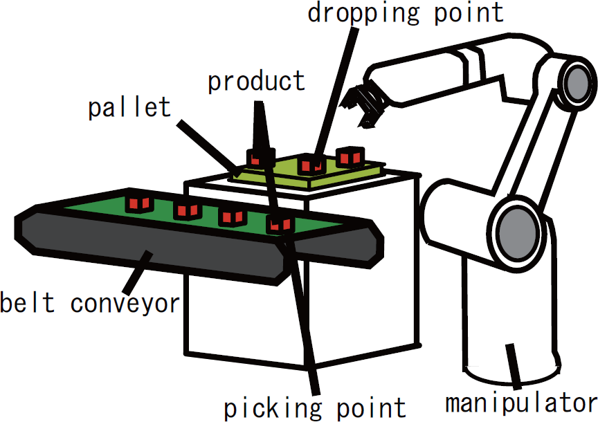
Palletizing with a manipulator
It is possible to reduce the cycle time (the time required to palletize all products) by designing an appropriate working environment that includes a manipulator base position, a pallet position and a pallet shape, and tailoring a manipulator motion. However, there is an interdependent relationship between the working environment design and the motion planning. In other words, the appropriate environment is determined by the motion of the manipulator, whereas the appropriate manipulator motion is determined by the environment. Therefore, to reduce the cycle time, it is necessary to design a working environment that takes the manipulator motion into consideration. Currently, working environments are designed by trial and error, based on the accumulated experience and intuition of the designer. Four problems may be encountered when designing an environment based on such a design method: (1) increased costs resulting from a trial-and-error environmental design, (2) the necessity of having a proficient designer, (3) increased costs when changing work details and (4) less optimal work efficiency. A working environment design method that reduces the burden on designers and achieves efficient operation is necessary.
With this background, the purpose of this research is to propose a working environment design method for palletizing using a manipulator with 6 DOF. Note that this study aims to be useful for upstream design that means to help designers to decide whether or not they should introduce the working environment design.
In Chapter 2, we introduce related works for the environmental design and discuss our originality. Chapter 3 sets out the conditions of this research. Chapter 4 discusses a proposed method. Chapter 5 discusses a simulation experiment to verify the validity of the proposed method. Finally, Chapter 6 summarizes this paper and discusses its conclusions.
2. Related Works
Research is being conducted on the base positions of manipulators, with the goal of establishing working environment designs that are more logical and appropriate. In this chapter, we introduce related works. However, each work cannot be described individually, because the space of this paper is limited. Therefore, we classified the relative works according to two important aspects, which are the kind of design parameters and the kind of design purposes. As with the design parameters, the manipulator and work pieces' positions are important. However, not only the placement but also other parameters, such as paths, motion and kinematics, are also important for work performance. As with the design purposes, the cycle time is also important. However, other purposes are proposed for the tasks' objectives and easy calculation, such as manipulability, dexterity, reachability, collision avoidance, force, torque and so on. Although almost all of these purposes can be quickly calculated mathematically, productivity is not always improved in comparison to the cycle time. Namely, it is necessary to consider the “cycle time” and to design the “various environment parameters”.
Only placement design methods for minimal cycle times were proposed by [1–6]. These studies did not design “various environment parameters”. The placement design methods for the other purposes were proposed by [7–22]. These studies did not consider the “cycle time”, nor the design's “various environment parameters”. Not only placement but also other important parameters have been simultaneously designed for cycle time shortening by [23, 24]. These studies are quite important to meet the demands of factories and are discussed later. Simultaneous designs have been made by [25–30], not for the cycle time but for other purposes. These studies did not consider the “cycle time”.
Although related research has involved the design of an appropriate working environment [23, 24] with the same motivation as ours for a point-to-point (PTP) path between the picking point and dropping point among a single or a few candidates, palletizing normally has multiple dropping points; thus, there are a lot of PTP paths between multiple points. In other words, it is necessary to determine all PTP paths between multiple points when calculating the cycle time, and a significant amount of computation time is required for the design of palletizing. Rapid path planning is required to overcome this issue of computation time and to design within a practical computation time. Moreover, the palletizing environment includes obstacles to avoid collisions. Therefore, path planning is difficult to achieve with much computation time.
3. Problem Settlements
3.1. Condition settings
Work conditions will be set in this section to clarify the scope of this research, with regard to the palletizing shown in Figure. 2.

Inputs and outputs of this design system
The manipulator workspace is fixed, and information (such as the shape and number of products, constraints on the pallet position, placement of obstacles) is already known when designing the working environment.
The manipulator is a vertically articulated manipulator with 6 DOF. Figures 3 and Tables 1 and 2 present the specifications of the manipulator utilized in this research.
Palletizing is accomplished through a multipoint PTP operation that moves the manipulator arm from its initial configuration (picking point) to the target configuration (dropping point) for all products.
The grasping orientation for picking and dropping points is fixed for all products.
The picking point and pallet height must be the same at the pallet's base position.
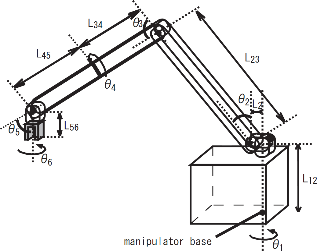
Model of manipulator
Manipulator specifications

Manipulator shape

The goal is to design the appropriate manipulator base position/orientation, pallet position/orientation/shape and paths from picking point to dropping points in order to reduce the cycle time, by designing the environment according to the proposed method.
3.2. Required specifications
This research requires the environment design to be completed in approximately 10 minutes. The goal is to design the environment quickly to determine whether to introduce a manipulator when planning the automation of palletizing. The proposed design method could be useful for upstream design to help the designers. Therefore, the designers need an immediate solution for how much improvement the factory can make with the working environment design, because the designers should discuss the matter with the factory side.
4. Palletizing Design Method
For the problem solving, we propose the overall algorithm, the procedures of which are listed below and shown in Figure 4.

Problem-solving algorithm
Manipulator specifications, product shape, product quantity, product grasping/placing orientation and obstacle position/orientation/shape are inputs (Figure 4(1)). These parameters are decided by the specifications of a factory and a task.
Initial values are set for configuration parameters. These configuration parameters are explained as the environmental design method in the next section (Figure 4(2)).
The cycle time is calculated and evaluated against the input configuration parameters. Manipulator path planning is required at this point to calculate the cycle time. In Section 4.2, we explain the evaluation method for these parameters as a motion planning method (Figure 4(3)).
The configuration parameter neighbourhood is searched for and evaluated. The neighbourhood search is utilized as the search method. In the neighbourhood search, searching moves toward the most highly evaluated option in the neighbourhood, in which each parameter has been slightly modified. Searching is deepened by repeating this procedure until the most highly evaluated parameter is found (Figure 4(4)).
If there is a neighbourhood that is more highly evaluated than its parameter, the most highly rated neighbourhood is set as the parameter, and the procedure returns to the fourth operation (Figure 4(5)).
If there is no neighbourhood that is more highly evaluated than current parameter, the parameter is the output as the design solution.
We will explain the detailed methods of “2. environmental design method” and “3. motion planning method” in the following sections.
4.1. Environment design method
4.1.1. Environment parameterization
The working environment consists of the manipulator base position/orientation, the pallet base position/orientation and the pallet shape. The design of a working environment requires many configuration parameters and the search space is highly dimensional. Six parameters are required to express the manipulator's position/orientation and also the pallet's position/orientation. Two parameters are required to express the rectangular aspect ratio of the pallet's shape. Altogether, there are 14 configuration parameters to set. We reduce the design time in this condition using the following expressions. The coordinates of the picking point in the XYZ coordinate system will be (0, 0, 0).
Manipulator base position:
As shown in Figure. 5, the manipulator's position and orientation are shown with the base position coordinates (m x , m y , m z ). Because the arm of the 6-DOF manipulator is not restricted by the base orientation, the parameters are not configured for the base orientation.

Parameters of the environment
Pallet position/orientation:
The pallet position is expressed as (p x , p y , 0), as shown in Figure. 5. The pallet orientation is expressed with an angle of rotation, θ, at the pallet centre. Originally, three parameters were needed to express orientation. However, the pallet is level, so its orientation can be expressed with only the rotation angle of the z-axis.
Pallet shape:
A rectangular pallet is utilized on the production site for the sake of practicality, so this research considers the pallet to be rectangular, as shown in Figure. 5. The number and shape of products are already known when designing the environment. Thus, the horizontal length of the rectangle, L, functions well enough as a configuration parameter.
Therefore, it is possible to limit the dimensionality of the search space by seven configuration parameters (m x , m y , m z , p x , p y , θ, L) for a 14-dimension working environment. The appropriate parameters are searched for among these parameters.
4.1.2. Representative points of the pallet
To calculate the cycle time, it is necessary to plan an arm path from the picking point to the dropping points of all products. This requires a significant amount of time. Therefore, this research does not make path planning for all dropping points, but does so for 10% of all product-dropping points and computes an approximate cycle time by calculating the takt time.
4.2. Motion planning method for evaluations
4.2.1. Passing point configuration method
The algorithm, illustrated in Figure 6, which is utilized to plan the path from the picking point to the dropping point via the passing point configuration method, is shown below.
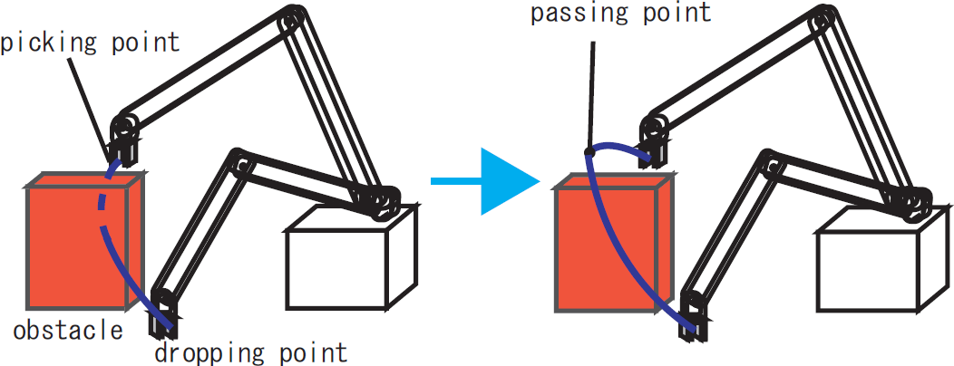
Path planning with the passing point
4.2.2. Collision detection
To determine a feasible solution, it is necessary for the planned manipulator path to avoid obstacles without error. In this research, we utilize fast collision detection [31] in paths between the picking point, passing point and dropping point. The sampling interval is set to 0.02 s, so sampling can be performed over an approximately 1-cm portion of the path. If a collision occurs, it is removed from the solution.
5. Evaluation Using a Simulation Experiment
5.1. Experimental conditions
A simulation experiment is conducted on a simulator, implementing the method described above. To verify the validity of the proposed passing-point configuration method, a comparison is performed with the results of an environment design that utilizes the state–time space method described in next section. The on-site environment design (described in Section 1) under comparison is performed according to following site rules.
The manipulator base is configured so that the picking point is positioned at 70% of the length of the manipulator arm, and is at the same height as the second joint.
The pallet is square, and it is configured so that it is directly to the side of the picking point, from the point of view of the manipulator.
The path is controlled by the configured position of the passing point, so the cycle time varies in the proposed passing-point method. We compare the results with the passing points, both a possible appropriate position and a possible inappropriate position.
A simulation experiment is performed with the following conditions input as the experimental conditions:
Manipulator: 6 DOF. The specifications are given in Figure 3, Tables 1 and 2.
Number of products: 100.
Product shape: cube of 10 * 10 * 10 [mm3].
Minimum distance between the picking point and the pallet: 400 [mm].
Obstacle shape: a 50 [mm] wall, as shown in Figure. 7.
Grasping orientation: products are grasped at the picking and dropping points in the orientation as shown in Figure. 7.
Conventional environment values are utilized as initial values (base position, pallet shape and pallet position/orientation) for parameter searching.
The picking point is fixed and the dropping points are different in all products. All products can be provided at any time at the picking point, because they are provided by the conveyer within the period when the previous product is being palletized by the manipulator.
Both grasping time and release time are ignored, in comparison, because these are not very long in duration and are common in other methods.

Obstacle and picking orientation
5.2. State-time space method for comparison
We introduce a method to not take much calculation time but to be near optimal as a comparison, in order to verify the proposed method. In this research, the joint angle changes according to the trapezoidal rule. The state–time space method is utilized to plan the shortest path that avoids obstacles from the picking point to the dropping point, by searching for the route in state–time space with the variables of joint angle, joint angular velocity and time. Fraichard utilized this state–time space to plan an obstacle avoidance path in a static environment for a robot with 2 DOF [32]. This research applies this method for use with a manipulator with 6 DOF.
5.3. Experimental results
Figure 8 shows the results of environment design, including the manipulator base position and pallet position/orientation/shape. The figure shows the system when viewed from the z-axis' direction. Figure. 8 (a) shows the outcome of the environment design using the conventional method, whereas Figure. 8 (b) shows the outcome of the environment design using the state–time space method. Figure. 8 (c) and (d) show the outcome of the environmental design using the passing point configuration method. Figure. 8 (c) shows the outcome of setting the passing point in the appropriate position, whereas Figure. 8 (d) shows the outcome of setting the passing point in an inappropriate position. Table 3 lists the resulting cycle times for each case. The conventional method's cycle time was calculated by planning a path using the state–time space method. The design time when using the state–time space method, as shown in Figure. 8 (b), was 1,900 minutes, whereas the design time of the proposed passing-point configuration method was three minutes.

Design results with a comparison of some possible methods
Cycle times of results

5.4. Discussion
A comparison between the conventional environment design method and the proposed environment design method: comparing Figure. 8 (a) and (c), the cycle time of the proposed method is approximately 5% less, and by designing an environment using this method, the cycle time is reduced. Comparing Figure. 8 (a) and (d), the cycle time of the proposed method is 20% longer. This is the result of differences in the path planning method. However, the cycle times resulting from the state–time space method are 175 s and 194 s, respectively, for the environment design in Figure. 8 (c) and (d). Comparing either result with the conventional method indicates a reduced cycle time, resulting in an environment design that improves work efficiency through the application of the proposed method.
A comparison between the state–time space method and the proposed method: comparing the cycle times of Figure. 8 (b) and (c), the environment designed using the proposed method results in a 10% increase. However, calculating the cycle time requires a massive 1,900 minutes of design time in state-time space method. Comparing the manipulator/pallet position in Figure. 8 (b) and (c), the distance between the picking point and base position, and the pallet position/orientation/shape, are similar for both methods. Therefore, the design time requirements were met, and an appropriate working environment can be expected through the use of the proposed method.
The effect of the passing point position on the environment design's results: when the cycle time is calculated by using the passing point configuration method shown in Figures. 8 (c) and 8 (d), the cycle time with an inappropriate passing point is 22% longer than that with an appropriate passing point. Although the configured position of the passing point varies according to the experience of the designer, in Figures. 8 (c) and (d), we can find that both manipulator base positions are far from the picking point, and that the pallet positions and orientations are similar. Even if an inappropriate passing point is configured, the characteristics of an efficient working environment can be understood.
As a future work, the method could be integrated into general simulators for the upstream design before a detailed design. For example, Autodesk Factory Design Suite, which is the simulator for factory design and analysis, could be utilized the detailed work environment design after our method has provided a rough solution. It should be an interesting challenge as a future work of research.
6. Conclusion
This paper proposed an environment design method that makes efficient palletizing possible for a manipulator with 6 DOF. A method was proposed for rapid manipulator path planning wherein a designer configures a passing point for the arm path, and an environment design that is able to satisfy the design time constraints was demonstrated.
Although this method results in slightly reduced work efficiency when compared with methods that design an environment using path planning, achieving an environment design with a practical design time is possible. Furthermore, the design solution of this method approximates that of methods using path planning in detail, demonstrating the validity of this method.
Footnotes
7. Acknowledgements
Portions of this research were carried out with the assistance of joint research between the University of Tokyo and DENSO WAVE INCORPORATED. This research is supported by Takehisa Fujita, who was at the University of Tokyo.