
Abstract
In this paper the latest results of an HIL architecture, optimized to develop and test UAV platforms are presented. This architecture has been used to realize the different devices involved in the navigation and stability control of the Volcan UAV, a plane designed to operate in volcanic environments.
The proposed architecture is strongly modular and flexible and allows the development of avionic hardware and software, testing and tuning the involved algorithms with non-destructive trials. A flight simulator (X-Plane) with a suitable plane model and plug-in, has been adopted to simulate the UAV dynamics. The flight simulator, interfaced with the real electronic boards, allows an easy tuning of all the control parameters and data collecting for test and validation.
The effectiveness of adopted methodology was confirmed by several flight tests performed subsequently by using the designed avionic modules on the real UAV.
Introduction
This paper describes the latest results of the methodology used in tuning the new autopilot board developed for the Volcan UAV and its architecture.
The DIEES at the University of Catania, Italy, is involved in several research projects concerning volcanoes and related problems. Some of these activities are within the Robovolc project (Robovolc Project, 2000), (Muscato G. et al., 2003), (Muscato G. et al., 2005) whose aim is to develop robotic systems for the exploration and analysis of volcanic phenomena.
The goal of the Volcan Project (Service Robots Group, 2008), (Caltabiano et al. 2005), (Astuti et al., 2007) is the realization of an autonomous system able to perform aerial surveillance and analyze the composition of gas inside volcanic plumes. In situ gas sampling is one of the more reliable techniques to obtain information about the concentration of the main components of the fumes (Alwyn S., 2002), (Aiuppa et al, 2002), (Symonds R. et al., 1994), (Stix J. & Gaonach H., 2000); for this reason the adoption of a flying machine seems to be the right choice (Ramanathan et al., 2007a), (Ramanathan et al, 2007b): all the required instrumentation can be carried directly into the plume to obtain measures collected before contamination due to the interaction with the atmosphere.
Besides application in volcanic environment, the Volcan UAV (Fig. 1) represents an efficient platform in all those situations where the direct intervention of human operators could bring high risk (Kontitsis et al., 2003), (Spry C. et al., 2005), (Ollero et al., 2005), (Merino et al., 2006); typical applications are:
intervention in industrial plants; forest fire-fighting services; natural disasters intervention; cooperation with other ground robots in demining operations, through aerial mapping (Longo et al., 2007).
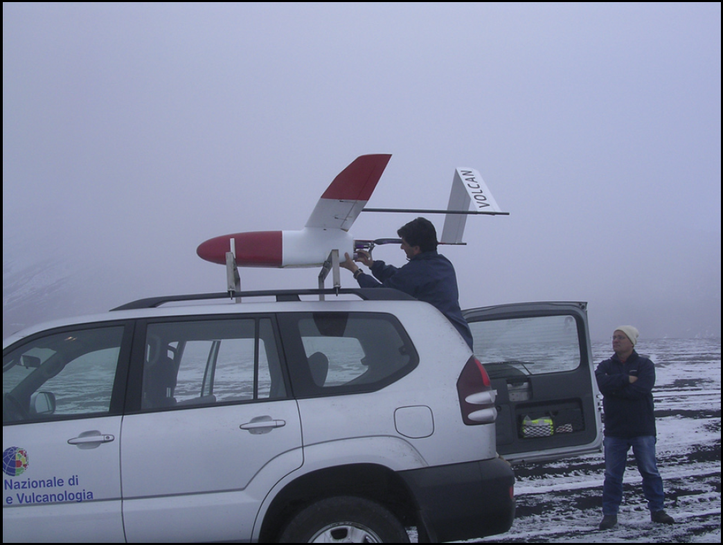
The Volcan UAV during the launch phase in a volcanic site on the top of Mt. Etna (2900m).
The payload of the Volcan UAV can be easily changed as each case requires: the implemented plug and play architecture allows easily mounting for example mono and stereo cameras, chemical sensors, infrared and thermal vision systems, data loggers.
After all, the main advantages of the adoption of the Volcan UAV are:
reduction of the number of needed operators; reduction of the risk for the involved operators; better identification of the causes and effect of the crisis; reduction of intervention time => faster response.
The environmental and working conditions in which the plane has to carry out the mission, suggested the adoption of an autonomous navigation system for the plane. There are two main problems that do not allow using a classic remote controlled UAV.
The first one is the long distance between a safe place and the volcanic plume. The volcanic scenario is very rugged and often it is not possible to find a runway in proximity to the crater; so, lift-off is usually executed in safe areas from where the teleoperations are very difficult due to the distance between the take-off area and the target plume.
The second problem is related to the loss of the line sight when the plane flies into the fumes: the gas within the plume is usually very dense and does not allow a visual recognition of the vehicle flying inside it.
In designing such a kind of system, several features must be taken into account. Among the others, problems related to high altitude flight and gas sampling technique. More details about Volcan UAV design and related problems can be found in (Service Robots Group, 2008), (Caltabiano et al. 2005), (Astuti et al., 2007).
A navigation system was developed with the aim of making Volcan UAV autonomous: a set of avionic modules that allow configuring the plane in every state of the flight and make the UAV capable of autonomous flight and payload control, was realized.
To develop the different devices involved in the navigation and stability control of the vehicle, a Hardware in the Loop (HIL) technique has been adopted: this architecture allowed realizing, testing and tuning each of the modules of the system. The implemented testing-bench based on the use of a commercial flight simulator, allowed to reduce the number of field trials with the real UAV, with a considerable reduction of development costs and time.
In the following section the control and navigation system architecture is presented. In Section 3 the implemented HIL architecture is described together with the development procedure used to realize the Air Data Attitude and Heading Reference System (ADAHRS) module of the autopilot. Several results will be presented at the end of the paper.
In order to plan and monitor an entire flight mission, a complete navigation and stability control system has been realized.
Several features make the implemented autopilot versatile and flexible, allowing to reconfigure the system and to adapt its behavior to the mission requirements; the main peculiarities are:
the type of control can be selected between a full waypoints based autonomous navigation and a pilot in the loop (PIL) mode. In the first case the autopilot takes care of both navigation and stability of the plane: the mission is planned via waypoints, placing on a georeferred map the position of each waypoint at the beginning of the mission. The mission can be easily modified during its execution by adding/changing/removing waypoints in the map. In PIL mode, the plane can be teleoperated from the control station by using a control-stick while the onboard autopilot attends to the stability of the aircraft; a user-friendly interface and a radio link allow a continuous exchange of data between the plane and the control station; a user friendly interface is used to display the plane position in real time on a map during the mission, to monitor some UAV parameters such as battery levels, speed, position and orientation, the sensors measurements. on line setting of navigation and stability algorithms parameters allows to reconfigure the autopilot, adapting its response to new supervened conditions. This important feature is fundamental in volcanic environments, where changes in the weather are very frequent.
The block diagram of the avionic architecture is represented in Fig. 2.

The block diagram of the navigation and stability control system. Blue squares represent the avionic modules, gray arrows show the data flow between the modules.
The system consists of the on-board modules and the ground control station: the avionic devices constitute the real autopilot, while the ground equipment is the base station from where to plan and monitor the mission.
Volcan UAS modules are:
FCCS - Flight Control Computer System
This module represents the core of the autopilot, since it attends to automatic flight navigation and stability control: data coming from Air Data Attitude and Heading Reference System are processed by control algorithms, to provide output commands to the Servo Actuator Control System (SACS).
ADAHRS - Air Data and Attitude Heading Reference System
This is the sensor board: it combines tri-axial angular rates, tri-axial linear accelerations, tri-axial magnetic field measurements, air data and GPS to provide a complete 6DoF attitude and pose solution.
SACS - Servo Actuator Control System
This module is connected to the R/C receiver to drive the servo commands and supplies them electrical power, derived from the onboard batteries. Optoisolated servo signals increase power supply noise immunity. Every SACS can control up to 8 servos or other peripherals and allows to activate manual override, through a normal RC Radio command.
GDLS - Ground Data Link System
This module provides for the radio link between on board electronics devices and the ground station; it is based on the MHX2400 COTS transceiver by Microhard System:
2.4000–2.4835 GHz ISM band; transparent, low-latency communication, providing true 115 kbaud operation; 60 miles, line of sight, with gain antenna.
GCI - Ground Control Interface
The ground control software allows to set-up the FCCS, configuring the control loops parameters. GCI permits easy “click and fly” operations, facilitating powerful mission planning, monitoring and in-flight adjustment on a notebook PC.
The communication between the functional units, which constitute the system of autonomous guide, is based on CAN bus and CANaerospace protocol; the latter exalts the characteristics of robustness and reliability, typical features of the CAN bus.
Simulation phase
The Hardware in the Loop architecture represents a powerful and cheap technique, that allows to develop and tune hardware, software and firmware of all of the modules that will be used in the real UAS (McManus et al., 2003), (Ashish Gholkar et al., 2004), (Johnson & Sumit, 2002). The trials executed on the testing bench are not a complete substitution of real flight tests, however HIL architecture is very helpful in the preliminary phases to find and solve bug and problems of both hardware modules and developed algorithms.
After all, the main advantage of this type of approach is the reduction of development time, costs and risks.
In Fig. 3 the architecture adopted in the development of the FCCS module is shown. In our case, X-Plane by Laminar Research has been used to simulate the flight dynamics of the Volcan UAV: a model of the plane has been realized by using a professional CAD software and imported in the simulator, to obtain a more reliable and accurate behaviour. A developed communication plug-in acts as an interface between the simulator and the real hardware: telemetry data concerning plane pose are sent through CAN bus to the autopilot board. Once attitude and position of the aircraft are known, the control algorithms implemented on the FCCS board compute the signals for the servo commands that are sent to the simulator to actuate the mobile parts of the plane.

Hardware in the loop architecture adopted in the development phase of the Flight Control Computer System. The dashed square represents X-Plane simulator together with the communication plug-in realized to allow data exchange between the simulator and the real FCCS hardware.
In (Astuti et al., 2007) an exhaustive description of the HIL architecture adopted in the working out phase of the FCCS module, was presented: the implemented control algorithms are described together with the complete hardware in the loop architecture, adopted to tune and test the real hardware device.
A similar architecture, shown in Fig. 4, has been implemented to develop the ADAHRS module. The X-Plane simulator supplies the data coming from the onboard Inertial Measurement Unit (IMU) and sensors: tri-axial angular rates, tri-axial accelerations, ground and air speed, GPS data are sent over CAN bus by the communication plug-in. Moreover, attitude and position of the simulated plane are recorded for an off-line comparison with the reconstructed pose.

Hardware in the loop architecture adopted in the development phase of the Air Data Attitude and Heading Reference System.
In this first phase, the ADAHRS was implemented on a development board with an 8bit Microchip PIC, implementing a sensor fusion algorithm based on an extended Kalman filter. Sensors raw data, coming from the simulator, are processed to obtain noise-free, compensated and stable data: roll, pitch and yaw angles, heading, latitude and longitude, air speed, barometric altitude, sensors compensated data. Signal filtering parameters are totally configurable through the user friendly PC interface via CANAerospace fieldbus.
Reconstructed data are then compared with the attitude data obtained from the simulator.
Since sensors data coming from the simulator are noise free and almost ideal, a special plug–in was implemented; in Fig. 4 the block “Artificial Noise” takes noise-free sensors data coming from the simulator as input and gives noise-added data as output. To obtain a reliable response from the simulated sensors, the real IMU was characterized. Several tests have been executed to test sensors behavior: vibration dependence, static and dynamic responses have been analyzed to introduce artificial noise with properties similar to the real one.
Moreover, these tests allowed implementing in the real hardware ad-hoc digital filters, able to guarantee high performance in all conditions and environments.
In Fig. 5 the true and estimated roll angles are shown: blue line represents roll angle coming from X-Plane simulator, red one is the angle estimated by the ADAHRS board by using the noise-added sensors data.
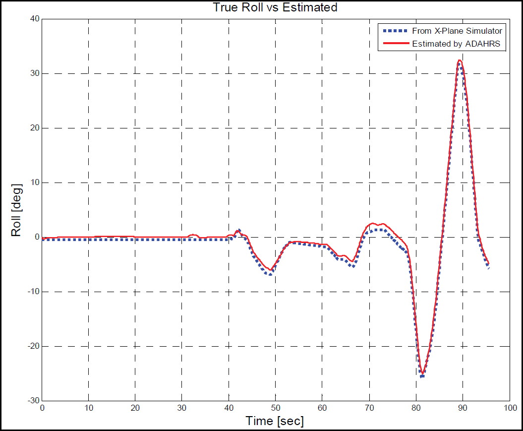
X-Plane Simulator roll angle (dotted line) vs. ADAHRS estimated roll angle (continuous line).
Maximum values of error committed in the estimation of roll and pitch angles are:
|E_roll| |E_pitch|
while average values are:
|mean{E_roll}| = 1.5° |mean{E_pitch}| = 1°
The next step was the implementation on the real ADAHRS hardware of the sensor fusion algorithms tested by using the development board. Once sensor fusion algorithms were completely designed and tested in simulation, raw data coming from real noisy sensor have been used.
The real implemented board (Fig. 6) is a strapdown low cost inertial navigation unit characterized by:
Freescale MMA 1220D accelerometer for the Z axis; Freescale MMA 2260 accelerometers for X and Y axes; Tokin tria-axial piezo gyros; Freescale MPX 5010 differential pressure sensor for air speed measurement (Pitot tube); Freescale MPXAZ4115A absolute pressure sensor for altitude determination; 10 bit AD converter; 2ND order hardware filters for analog sensors filtering; commercial GPS receiver.

Air Data Attitude and Heading Reference System.
The same sensor fusion algorithms used during the HIL simulation phase, have been used on the microcontroller of this board; just a replacement of the simulated sensors data with the value coming from the real sensors, was needed.
Fig. 7 and Fig. 8 show a comparison between the developed ADAHRS and a commercial inertial measurement unit, the MTi by XSens.

MTi roll angle (dotted line) vs. ADAHRS estimated roll angle (continuous line).
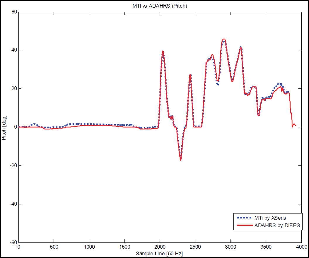
MTi pitch angle (dotted line) vs. ADAHRS estimated roll angle (continuous line).
Experimental results:
maximum error values:
|E_roll| |E_pitch|
while average values are:
|mean{E_roll}| = 0.2° |mean{E_pitch}| = 0.5°
The validity of adopted methodology was confirmed by several flight tests performed by using the designed autopilot on a real UAV.
Fig. 9 shows the aircraft response when it was flying in level flight and 30° roll angle was assigned to the autopilot as reference: the blue line is the measured roll angle, the red one is the reference angle. The sampling time was 10ms.
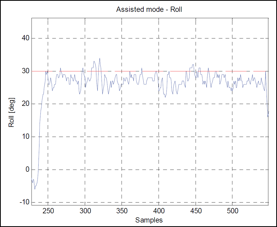
Aircraft response when the plane was in level flight and 30° roll was assigned as reference to the autopilot: the continuous line is the measured roll, the dashed one is the reference roll angle. The sampling time was 10ms.
Fig. 10 shows the roll angle when a wide change in roll angle was executed; while plane was flying with a roll angle of −30°, a 30° roll angle reference was assigned to the autopilot. The blue line is the measured roll angle, the red one is the reference angle. The sampling time is 100ms.

Measured roll angle (continuous line) when aircraft was flying with a roll angle of −30° and a roll reference value of 30° (dashed line) was assigned to the autopilot. The sampling time was 100ms.
The implemented testing-bench based on the use of a commercial flight simulator and of a hardware in the loop architecture, allowed reducing the number of field trials with the real UAV, with a considerable reduction of development costs and time.
This kind of architecture permitted the realization of a complete navigation and control system, based on the use of an implemented low cost strapdown inertial measurement unit, able to furnish stable and accurate measures even in presence of great noise and disturbance. The effectiveness of adopted methodology was confirmed by several flight tests, performed subsequently by using the designed avionic modules on the real UAV.
Footnotes
5.
This work was carried out in cooperation with OTe Systems Catania, Italy (OTe Systems, 2008).