
Abstract
The aim of this paper is to present a novel approach to swarm control of small fixed-wing UAVs, which combines only two flocking behaviours with a leadership feature. In the presented approach, two fundamental rules of Reynolds flocking are applied, i.e., cohesion and repulsion, as the base of a decentralized control of self-organization of the flock. These rules are combined with a leadership feature, which is responsible for a global behaviour of guidance, as in the case of animals. Such a bio-inspired combination allows the achievement of a coherent collective flight of a flock of fixed-wing UAVs without applying formal behaviours of migration and alignment. This highly simplifies an implementation of the algorithm. The presented results include both numerical simulations and experimental flights, which validate the hardware implementation of the approach.
1. Introduction
Applications of swarm behaviours in robotics have been extensively developed for many years, resulting in the coherence of research areas such as swarm intelligence, multi-agent systems, robot collaboration, formation control, autonomous agents and sensor networks. All of them together create a multidisciplinary research area. Due to the obvious complexity of the problem, most of the research carried out on swarm behaviours is limited to selected simulations or laboratory experiments that are focused on robots having the capability of omnidirectional motion [1]. In this case, it is easier to control robots' interactions and the risk of communication failures is also minimized. The swarm of nano-quadrotors presented by GRASP Laboratory from University of Pennsylvania is an impressive example of such an approach [2]. The demonstration flight is very impressive but the possibility of outdoor usage and the level of the quadrotors' autonomy can be questioned. The autonomous control of a swarm of non-holonomic robots, which are able to operate in outdoor environments, becomes much more complex and complicated, due to the increased importance of robustness and autonomy. These issues in particular concern a non-holonomic system, such as fixed-wing unmanned aerial vehicles (UAVs). A team of fixed-wing UAVs must be more robust against failures of the agents and of the communication, in order to achieve coherence of the team. The same concerns simpler methods such as the leader-follower approach and its variant, which is based on a two-stage switching control [3].
Most approaches concerning the problem of formation control usually suffer from high computation costs and centralized structures of control loops [4]. Therefore, research areas have become more focused on the Reynolds flocking theory, inspired by the behaviours of bird flocks. In [5], flocking rules and UAVs as mobile nodes are applied to increase connectivity in a mobile ground network. Gyroscopic and braking forces could be applied to produce flocking behaviour with obstacle avoidance [6]. To control the rules of cohesion and avoidance, a vision system with a wide field of view of up to 180° is used as a perception technique for relative UAVs' positions [7]. Demonstrations of simple rules for following and flocking in three dimensions can be performed with the use of a small and lightweight robotic system, which is composed of helium blimps [8]. Swarm control based on aerial flocking is popular because it assumes a decentralized structure of control, which is implemented locally, and which for this reason improves the robustness of the flock against failures of any robot. However, it also requires a much greater level of individual autonomy of the robot. One of the important advantages of aerial flocking is scalability, which allows the number of robots to be easily increased, in order to extend the capability of the flock. The principal rules of aerial flocking were formulated by C.W. Reynolds, who was inspired by the behaviours of birds [9].
Most of the articles mentioned above concern only numerical simulations of rules of Reynolds flocking which are applied to swarms of UAVs. Despite these articles, there is a gap between theory and practice because only a few applications of aerial flocking have been brought to reality. An example worth noting of real implementation of aerial flocking which uses fixed-wing vehicles can be found in [10]. Its authors used up to 10 small UAVs to create a flock, which was essential to discover the relation between the maximum communication range and the dynamics of the vehicle. It is a very valuable example because it was applied to fixed-wing UAVs, as opposed to more popular quadcopters [11] or blimps [8]. The authors indicated indirectly that the experiment was limited to 2D, which is reflected in the results presenting horizontal projections of flight trajectories. All the vehicles were flying at constant altitudes, maintaining a 10-metre vertical spacing to achieve a priori collision avoidance, although the repulsion behaviour was implemented. The inter-vehicle communication was based on USB Wi-Fi dongles with a maximum range of 300 metres, which is a relatively short range. Considering the main aim of the research, which is to determine the relation between the communication range and the minimum turn radius and its impact on the cohesion behaviour, the wireless equipment was adequate. Unfortunately, the research does not demonstrate the potential usability of the flock because all the UAVs only make circles around a virtual migration point. This increases the stability of the flock if the range of corrections of pitch and roll is limited only to small angles. Flying along in a figure of eight would be more reliable.
The major aim of this survey is to present a computationally efficient algorithm of aerial flocking that can be applicable in the case of small fixed-wing UAVs and simultaneously usable in practical applications. Thus, the primary feature is to reduce flocking behaviours only to cohesion and repulsion defined globally to achieve a self-organization behaviour of the flock. It is based on two conditions of lateral and vertical equilibrium between cohesion and repulsion and the alignment of individual airspeeds in the longitudinal. This will be investigated using numerical simulations, the results of which should show coherent flights of five UAVs. The second feature included in the presented algorithm is the selection of a leadership which will be fully controllable from the ground control station and will play the guiding role of the flock. The leader as the guide of the flock becomes a bridge to control indirectly the position of the entire flock. Such hierarchical structure gives more flexibility in motion control or in preparation of the mission programme, because GCS will communicate only with the leader. The rest of the flock, which tracks the centre of gravity, is not only able to reach an assigned target point collectively, such as can be done by behaviours of migration and alignment, but also track even complex trajectories of the leader with the same dynamical constraints.
The motivations for choosing the leadership instead of behaviours of migration and alignment can be found in [12], where there is a discussion concerning literature on the commonly used flock models. Some of them, assuming the heterogeneity of the flock, show how the leaders or informed members of the flock can affect the motion of the flock [13]. The migration route can be imposed by the leadership, which may be a single member or a small group of flock members with information about the destination of the movement, e.g., the location of a source of food in the case of animal flocks. Hence, the leadership can play the guiding role in the navigation of the flock. A similar hierarchical structure of pigeon herds was discussed in [14]. Thus, the selection of the leadership in the flock seems to be a good idea and could be treated as a bio-inspired solution. There are many other examples of imitating hierarchical structure of animal flocks that try to implement a fully controllable leadership for outdoor flocking with aerial robots [11] or for distributed sensing [15]. The article ends with the results of in-air experiments that verify separately each flock behaviour used in the implementation of the presented approach. Splitting the experiment into separate tests on applied behaviours helps us to understand and analyse how a fixed-wing UAV will behave due to a limited turn radius.
2. A Model of a UAV Flock
The main feature of the described approach is to introduce the leader as the guide of the flock, which does not have to apply flocking behaviours by itself. Thus, it could be fully controllable by the ground control station (GCS). Nevertheless, the leader is also a member of the flock, as well as a node in the communication network of the flock, and is to broadcast its own coordinates and airspeed to other UAVs.
The novelty of the approach consists in the fact that, if the leader is controlled by the ground control station and spacing between UAVs is wide enough, cohesion and repulsion behaviours defined globally will be enough to stabilize and to organize the flock. Migration and alignment behaviours will be achieved indirectly as the result of lateral and vertical equilibrium between cohesion and repulsion. When the leader departs from the flock, other vehicles organize themselves by endeavouring to lateral and vertical equilibrium between behaviours of cohesion and repulsion individually for each UAV, which can be visible as a gradual aggregation of UAVs. It lasts until the minimal allowable spacing between UAVs is reached and their courses and airspeeds are aligned. Other than achieving lateral and vertical coherence, behaviours of cohesion and repulsion in the longitudinal direction will move all UAVs, except the leader, towards the centre of gravity as if it was a virtual migration point. In turn, the centre of gravity tracks the leader, keeping an average airspeed of the flock. Thus, the presented approach is a combination of the decentralized structure of aerial flocking and the hierarchical approach of leader-follower. The proposed structures of the flock and the local control of the UAVs are presented respectively in Figures 1(a) and 1(b) [10].

(a) the structure of an exemplary flock of four UAVs, (b) the structure of the local control
According to Figure 1, only UAV1, as the leader, receives commands from the GCS and uses waypoint locations to calculate flight direction. All UAVs in the flock broadcast their own navigational data to the others. Thus, every UAV is able to know the position of the centre of gravity and the positions of all UAVs in the flock. This information is sufficient to calculate individually desired heading and pitch, as the result of cohesion and repulsion defined globally. A decentralized and hierarchical structure of the proposed algorithm means that the GCS is able to control the flock via the position of the leader and, simultaneously, the control of flocking behaviours is a high-level control loop in relation to the navigation control of the autopilot. A decentralized structure also means that all UAVs calculate their individual behaviours locally, according to the received information. As the position and the airspeed of the leader are deterministic components of the position and the airspeed of the centre of gravity, it will modify the courses and airspeeds of the other UAVs by the change of the point of the lateral or vertical equilibrium. Such a relation between the leader and the centre of gravity makes situations in which the leader just flies away from the flock or the flock moves uncontrollably after the loss of the leader not possible to happen.
As was previously indicated, the proposal of flocking control is based only on behaviours of cohesion and repulsion. The first behaviour depends on the position and the airspeed of the centre of gravity, which are formulated by equations [17] that were modified to improve coherence of the flock:

Where:
If the position of the centre of gravity is known, each UAV is able to determine the direction of cohesion. However, the cohesion behaviour is only valid if the distance between the UAV and the centre of gravity is greater than D
safe1
, which is presented in Figure 2. This limits the range of cohesion and defines the maximum span of the flock. The centre of gravity is not exactly a geometrical centre of the flock. It should lie halfway between the position of the leader and the point which is defined as the average sum of positions of the rest of the UAVs. This secures the flock against a situation in which the centre of gravity, instead of tracking the leader, follows the rest of the flock, which just flies away from the leader. The direction of cohesion can be simply expressed as a normalized vector

Where:
Unlike the cohesion, the repulsion behaviour does not require any information about the position of the centre of gravity. It uses the coordinates of all the UAVs to prevent collisions inside the flock and to organize the flock by keeping a minimal safe spacing between all UAVs. The consequence is that each UAV in the flock must know the coordinates of the rest of the UAVs, to calculate a distance from any other UAV and to keep it above a specified threshold. The rule of repulsion is also presented in Figure 2.
The normalized vectors

Where:
When both behaviours of repulsion and cohesion control the flight of a UAV, the flight direction is determined by the vector

Where: αnm – the m-th strength of repulsion assigned to the vector
As avoiding collisions with the nearest neighbours is the highest priority, the repulsion vectors related to them should dominate over those that are related to further neighbours. Therefore, the vector
The UAVs are controlled simultaneously by a combination of behaviours of cohesion only if UAVn and UAVm are further from the centre of gravity than the distance D
safe1
and they are too close to each other. Therefore, the resultant vectors

Where:
Where: αnm – a strength of repulsion assigned to the vector
For the conditions of lateral and vertical equilibrium to be fulfilled, the distance between the UAVs should be lower than D
Safe2
and the distance of each UAV from the centre of gravity should be higher than D
Safe1
(Fig. 2). If the conditions in (6) are met, UAVn will fly forward keeping a constant direction that is defined by
Longitudinally, the flock can be stabilized by applying the airspeed of the centre of gravity, which is the average airspeed of all the UAVs (1), as a set-point for local control loops of every UAV. In this way, the airspeeds of all UAVs in the flock will be aligned (Eq. 7), providing the longitudinal coherence of the flock. As PID loops of low-level control apply the following parameters, i.e., the desired heading angle, the desired pitch angle or the desired airspeed as their set-points, these parameters should be calculated by the control of flocking behaviours. If

Where:

An illustration of combined repulsion and cohesion behaviours which result in the aligned vectors
3. Numerical Simulations
The result of simulations (MATLAB – SIMULINK) that were run to verify the effectiveness of the proposed algorithm and the possibility of coherent and collective flight without behaviours of migration and alignment is presented in Figure 3. In the simulations, four UAVs managed to track collectively the trajectory of the leader, although the initial positions and headings of all UAVs were different. Moreover, the distances between all UAVs decreased gradually until they reached the minimum permitted distance between the UAVs. The headings of all UAVs were also aligned gradually to the heading of the leader; thus the effect of alignment is visible. This means that the combination of cohesion and repulsion is sufficient to control the coherence of the flock and the lateral and vertical equilibrium between behaviours (Eq. 7 and 8) cooperating with the longitudinal speed alignment is achievable. It could be observed as a parallel and collective flight of five UAVs and this was achieved without formal behaviours of migration and alignment. In the approach, the centre of gravity of the flock becomes a dynamical migration point.

Results of the simulations presenting flight trajectories (a) and (b) of the exemplary flock of five UAVs, through three different sequences of four waypoints starting at different initial positions. The trajectory of the leader is in blue (UAV1). On the right side, there are plots of 10 relative distances for each pair of UAVs - 3(c) is related to 3(a), 3(d) to 3(b).
In the simulations, it was assumed that there are no external disturbances. The simulation parameters are as follows: speed - 10 m/s (initially - 0), minimum distance between UAVs - 15 metres and maximum distance from the centre of gravity - 5 metres.
Figure 3 presents the results of the simulations. The respective flight trajectories are in subfigures 3(a) and 3(b), with the relative distances between UAVs in 3(c) and 3(d). Based on 3(c) and 3(d), it can be noticed that the lines of relative distances are split into two groups at the ends of the simulations. The group of upper lines relates to the distances between the leader and four other UAVs and the group of lower lines represents the distances between these four UAVs. Hence, it can be observed that the leader was flying about 75 metres ahead and that the distances between four followers varied from 15 to about 25 metres. These graphs confirm the coherence of the flock, which is controlled only by cohesion and repulsion.
The conclusion from Figure 3 can be strengthened by Figure 4, where the flight trajectories are presented in subfigure 4(a), graphs of pitch angles in 4(b), graphs of airspeeds in 4(c) and graphs of heading angles of four followers in Figure 4(d). It can be noticed that the followers' headings, pitch angles and airspeeds were aligned to the heading, the pitch and the airspeed of the leader gradually over time. Obviously, an inertia between the leader and the followers can be found, but it decreased over time in accordance with the decrement relative distances between UAVs.

Results of the simulation: (a) – trajectories of five UAVs creating the flock (yellow diamonds are start points), (b) – airspeeds of all UAVs (the airspeed of the leader is in blue), (c) – pitch angles of all UAVs (the pitch of the leader is in blue), (d) – heading angles of all UAVs (the heading of the leader is in blue)
4. Experiment and Results
To validate the implementation of the developed approach, which will provide a sufficient level of the individual UAV autonomy, an experimental setup was prepared, i.e., two identical aircraft (twin-engine TwinStar from Multiplex) with essential equipment for a UAV, i.e., advanced autopilot (MP2128Heli), 868 MHz radio modem (XBee Pro) to create a wireless network inside the flock and 2.4 GHz radio modem to maintain communication with the ground control station (with Horizon software). The structure of the hardware applied in the experiments is shown in Figure 5. Thus, it was possible to prepare simple outdoor tests showing how the algorithm is able to switch the control of a UAV from traditional navigation through a sequence of waypoints to flocking behaviours (Fig. 1(b)) and not just around a static migration point, as is done in [10]. This also means that the tests should tell us how cohesion or repulsion responds to various instances of relative orientation of UAV2, in reference to the centre of gravity or to UAV1 respectively. The results should allow us to find weak points of the approach and, particularly, verify the impact of the integration of the algorithm with the autopilot on the smoothness and the effectiveness of control of the UAV flight. It is essential to analyse the output values of the algorithm before a test flight of the flock of UAVs.

The structure of the hardware applied in the experiments. Arrows drawn with a solid line represent a permanent radio communication between UAVs; arrows drawn with a dashed line represent a temporary radio communication used to manage autopilots.
To verify clearly the implementation of the flock behaviours, the experiment was split into two separate tests concerning cohesion and repulsion respectively. In each test, the role of the leader was assigned to the aircraft labelled as UAV1. As the leader does not apply any flocking behaviours and only broadcasts its position and speed, it could be stationary. The second aircraft, i.e., UAV2, flew around the position of the leader in accordance with the flight route that is defined by four waypoints (Fig. 6). Such a testing scheme allows us to explore the response of flocking behaviours to a wide range of different relative orientations between UAV1 and UAV2 and between UAV2 and the centre of gravity. This is also the safest way to test the algorithm. According to simulations, to enable the observation of interactions inside a flock created with more than two UAVs, the flock would have to fly at distances longer than a few hundred metres. It will significantly increase the level of risk, especially if there are no areas where such experiments are allowed to be carried out. The prepared testing schemes for cohesion and repulsion tests are an alternative method to the idea of flying around a static migration point in the same direction and they are presented respectively in Figure 6(a) and Figure 6(b).

Schemes of two separate tests: (a) for the cohesion behaviour test, (b) for the repulsion behaviour test. The green diamonds represent a sequence of waypoints. Circles drawn with a dashed red line indicate the range of repulsion (D safe2 ) and those drawn with a dashed green line indicate the range (D safe1 ) outside which there is no cohesion.
To induce the effect of cohesion, the threshold values of D safe1 and D safe2 should be as low as possible (D safe1 = 0 m and D safe2 = 0 m). Hence, if UAV2 flies around the leader at any distance greater than D safe1 and D safe2 , only cohesion will be observed. Whereas, in the case of the repulsion test, these thresholds must be greater (D safe1 = 381 m and D safe2 = 381 m) than the maximum achievable distance between UAVs in the test. This ensures that only the repulsion behaviour will be observed during the repulsion test. In each test, the altitude of the leader was set manually to be about 80 metres. It was required to compensate for a substantial difference in real altitudes, which could cause UAV2 to descend towards the ground and crash. The flight altitude for UAV2 was set to 150 metres above the ground level in the case of the cohesion test and to 80 metres in the case of the repulsion test.
In both tests, all parameters of the flight are logged, including the position of the centre of gravity and the values of set-points for the low-level control loops of UAV2, i.e., desired heading and desired pitch. Figure 7 present the flight path that was logged in the cohesion behaviour test. The red point indicates the position of UAV1. The green diamonds are the sequence of four waypoints. During the test, wind speed was nearly 5 km/h.
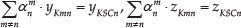
In Figure 7, with a trajectory of UAV2, there are green points numbered from one to four. They were selected to verify the values of set-points for the low-level control loops, which were calculated in the cohesion behaviour test. At these points, it can be noticed that UAV2 is differently oriented in reference to UAV1 and the centre of gravity, which allows us to assess the response of the cohesion behaviour. Table 1 compares the responses of the cohesion behaviour test, i.e., the desired heading, the desired pitch and the elements of vector
Responses of the cohesion behaviour at points marked in Figure 7

A trajectory logged in the cohesion behaviour test. The red point – the position of the leader (UAV1). The green points are the moments which will be used to verify values of set-points for the low-level control loops.
Comparing the values of the desired heading given in Table 1 with the real positions of UAV2 marked by the green points in Figure 7, it can be stated that these values are calculated correctly, if it is assumed that UAV2 should be attracted to the centre of gravity, lying halfway between UAV1 and UAV2. The expected directions of cohesion are defined respectively by the following directions: north-east-down (point 1), north-west-down (point 2 and point 4) and south-down (point 3). Hence, the calculations made by the implementation of the approach will always push UAV2 towards the centre of gravity if the distance between the centre of gravity and UAV2 is greater than D Safe1 .
The next part of the experiment was the repulsion behaviour test. The same testing procedure was applied and only the threshold values of D safe1 and D safe2 were modified to induce a repulsion effect. Figure 8 presents plots of the trajectory of UAV2 logged in the repulsion test.

A trajectory logged in the repulsion behaviour test. The red point – the position of the leader (UAV1). The green points are the moments which will be used to verify the values of set-points for the low-level control loops.
Table 2 contains a comparison of responses of the repulsion behaviour at the points marked in Figure 8. As before, comparing the content of Table 2 with the real positions of UAV2 presented in Figure 8 delivers a proof that the desired heading calculated by the implementation of the approach is coherent with the expected direction of repulsion. Based on the values from Table 2, it can be stated that UAV2 is capable of achieving the effect of repulsion from UAV1, to avoid a collision if the distance between them becomes lower than D Safe2 . The expected directions of repulsion for selected positions of UAV2 are defined respectively by the following directions: south-west-down (point 1), west-up (point 2), north-east-up (point 3) or south-east-up (point 4).
Responses of the repulsion behaviour at points marked in Figure 8

Figures 9(a) and 9(b) present the trajectories of UAV2 logged in final test flights, which were performed to show how the flight path is modified respectively by cohesion or repulsion behaviours [17]. This time, the effects of cohesion and repulsion could also be observed separately. In Figure 9, the red colour indicates selected parts of the flights that give clear evidence of the effects of the cohesion and repulsion behaviours, shown respectively in Figures 9(a) and 9(b). The red diamonds are the next waypoints in the flight programme, where a UAV should fly to, but, instead of this, the flight control is overtaken by the flocking algorithm. The points labelled “A” and “B” relate to the moments when the cohesion or repulsion behaviours were respectively activated and deactivated.

The trajectories of UAV2. (a) the cohesion behaviour test, (b) the repulsion behaviour test. The red diamond on the left side is the waypoint that should be reached after flying over point “A”. Points “A” and “B” relate to the moments of activation and deactivation of the cohesion or repulsion behaviours.
Thus, Figure 9(a) indicates that UAV2 flies around and towards the leader until the cohesion rule is active, instead of flying towards the point marked by the red diamond. Figure 9(b) shows that UAV2 avoids the leader's location while it is commanded to fly towards the waypoint (the red diamond), which is lying diagonally on the opposite side of the leader. The parts of the trajectory in Figure 9(b), which are located near to the leader, relate to the flight at higher altitude or to the phases of take-off or landing. As a result, UAV2 managed to change its trajectory to avoid the position of the leader, as it is defined by the repulsion behaviour by the repulsion behaviour.
Obviously, the results of the experiments are limited in some sense and not comprehensive enough to predict all interactions between UAVs in larger swarms. Nonetheless, they give the first view of the UAV behaviour in a real flight through a sequence of waypoints. A relation between minimal turn radius, which is limited only to about 50 metres, and the cohesion behaviour can also be observed. This minimal turn radius corresponds to a roll angle of about 30 degrees, which provides lateral stability of a UAV without slipping. However, it makes reaching the position of the centre of gravity by UAV2 impossible. Therefore, the minimal turn radius makes it circle around the leader. Another issue that causes difficulties for testing the flocking algorithm is due to restrictions in the public area that limit the usage of UAVs over large spaces. To avoid these restrictions, UAVs could make circles around the migration point, but this does not give comprehensive results either [10]. For the same reason, quadcopters or other omnidirectional vehicles are preferable in such fields of research.
5. Conclusions
Aerial flocking is an attractive possibility to achieve a coherent flight of a group of fixed-wing UAVs. The principles of aerial flocking are formulated on the basis of bird flocking behaviours. There is very little research focused on comprehensive experiments with aerial flocking applied to fixed-wing UAVs. Therefore, a minimalist algorithm of flocking behaviours, which combines only two simple behaviours of cohesion and repulsion with a leadership feature, was elaborated. Such an approach could be integrated with other functions of the autopilot, which would reduce the amount of required hardware on board an autonomous UAV. The results of the numerical simulation prove that the combination of behaviours with a leader-follower approach makes it possible to reduce the number of used behaviours without losing the coherence of the flock, neither lateral, nor vertical, nor longitudinal. Achieving the effects of migration and alignment behaviours is still possible, but probably in longer time, due to inertia. In the case of long-distance multi-UAV missions, it does not really matter. Simultaneously, the proposed approach will offer full control of the flock, if all UAVs align their speed, pitch and heading to the leader, controlled by GCS, as was presented. The verification of the implemented algorithm succeeded by performing the experimental flights, which are based on commonly used hardware. The major purpose of the experiments is the validation of cohesion and repulsion behaviours and a prediction of responses of a UAV that are adequate for those behaviours. The experiments explore this for a wide range of relative positions and orientations, which is more comprehensive than a flight around a migration point.
Footnotes
6. Acknowledgements
The research was funded by statutory funds of the Department of Automation and Robotics, Faculty of Mechanical Engineering, Białystok University of Technology (S/WM/1/2016). The article is an extended revision of the presentation that was given at the 10th International Conference on Mechatronic Systems and Materials in 2014 (Opole, Poland) and it is permitted to be published in any journal. No figures used in the article have been previously published anywhere else and it is related to the prior.