
Abstract
In this paper, an improved reconfiguration control scheme via an H∞ fault observer and adaptive control is studied for the quad-rotor helicopter with actuator faults. The bilinear problem is eliminated by constructing fault compensation and control law reconfiguration in the adaptive controller. Fault estimation is achieved by designing the fault observer with an H∞ performance index, which is applied to evaluate the ‘locking in place’ fault of the actuator in a quad-rotor helicopter. By drawing the H∞ performance index into the adaptive fault observer, an asymptotically convergent estimated error can be attained and the burden of the adaptive controller is alleviated. Some simulation and experimental results confirm the availability of the reconfiguration control scheme.
1. Introduction
The essential needs of surveillance, rescue, military and security applications put unmanned aerial vehicles (UAV) have been central to the concerns of researchers and engineers in the last decade than in any period since. The quad-rotor helicopter, as a novel type of UAV aircraft, has become an attractive topic, given its new appearance, simple structure, low cost and special features [1–5]. However, the possibility of system faults may be increased under some rugged flight conditions. Meanwhile, the system behaviour can deteriorate when actuator, sensor or plant faults take place. Many control approaches have been investigated for the quad-rotor helicopter, such as back-stepping control [6], sliding mode control [7], LQ control [8] and neural network control [9], to solve these problems.
Model-based fault detection and isolation (FDI) algorithms have been the subject of intensive investigation over the past two decades [10–14]. Furthermore, many schemes considering actuator faults have been proposed in succession, such as the observer-based method [15], the parity space method [16] and the multiple model-based method [17]. Due to the increasing complexity of the products concerned and the demand for safer processes, more and more attention is being paid to the application of reconfiguration control. Considering the stability and good performance of the control system in faulty cases, the fault identification information is needed to realize the reconfiguration of control law. Thus, the complex changes of the system dynamics can be handled rapidly. The problems of fault detection and estimation for non-linear dynamics are considered by [18]. An issue concerning observer-based integrated robust fault estimation and accommodation of a class of discrete-time uncertain non-linear systems is studied by [19]. [20] addresses the problem of fault detection and diagnosis (FDD) for the quad-rotor helicopter with actuator faults. A sliding model observer-based fault estimation method is presented by [21] for a class of non-linear networked control systems with transfer delays. [22] proposes a fault-tolerant control scheme for non-linear sampled data systems via an Euler approximate observer. But the convergence speed of the estimation algorithm is also an important factor with respect to the assessment of the adaptive observer. The
In this paper, an
The following part, Section 2, describes the quad-rotor dynamics, while actuator fault models are presented and formulated in Section 3. Section 4 illustrates the design of the adaptive controller. The proposed fault observer is given in Section 5 in detail. Some simulation and experimental results are shown in Section 6. Finally, conclusions are drawn in Section 7.
2. Quad-rotor Dynamics
The quad-rotor aircraft is controlled by the angular speeds of four electric motors as shown in Figure 1. Each motor produces a thrust and a torque, whose combination creates the main thrust, the yaw torque, the pitch torque and the roll torque acting on the quad-rotor [25]. Conventional helicopters modify the lift force by varying the collective pitch. Such aerial vehicles use a mechanical device known as a swash-plate. This system interconnects with servomechanisms and blade pitch links in order to change the rotor blades' pitch angle in a cyclic manner, so as to obtain the pitch and roll control torques of the vehicle. In contrast, the quad-rotor helicopter does not have a swash-plate, but has constant pitch blades. Therefore, in a quad-rotor, we can only vary the angular speed of each one of the four rotors to obtain the pitch roll control torques.

Pitch, roll and yaw torques of the quad-rotor helicopter
The dynamical model of the quad-rotor helicopter is obtained by representing the aircraft as a solid body evolving in a three-dimensional space and subject to the main thrust and three torques: pitch, roll and yaw [26–28]. The mathematical model described in this section relies on the following assumption:
2.1. Modelling of the rotation
The thrust generated by each propeller can be modelled as a first-order system described by:

where u is the PWN input to the actuator, ω is the actuator bandwidth and K is a positive gain. A state variable, v, is used to represent the actuator dynamics, which are defined as:

Two propellers contribute to the motion in each axis. The rotation around the centre of gravity is produced by the difference in the generated thrusts. The roll/pitch angle θ can be formulated using the following dynamics:

where

are the rotational inertia of the device in roll and pitch axes. L is the distance between the propeller and the centre of gravity.
The motion in the yaw axis is caused by the difference between the torques exerted by the two clockwise and the two counter-clockwise rotating propellers. The dynamic equation of the yaw axis can be described by:

where
2.2. X, Y, Z dynamics
The motion of the quad-rotor along the X and Y axes is caused by the total thrust and changing roll/pitch angles, while the motion in the vertical direction (along the Z axis) is affected by all the propellers. Dynamics of the

where
3. Fault Formulation
3.1. System modelling
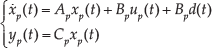
As shown in Section 2, the non-linear gyroscopic effect resulting from the rigid body rotation in space and the coupling of the attitude angles are both ignored to construct a linear model of the quad-rotor aircraft. We can then obtain a linear control system in this normal form:
where
3.2. Fault modelling
Actuator fault is a typical problem of the flight control system and can be divided into two categories according to the level of seriousness: complete failure and partial failure. The former type includes locking in place (LIP), hard-over fault (HOF) and floating. The latter implies the loss of effectiveness (LOE) in control capability. The actuator fault for consideration in this paper can be presented as a second-order model as follows:
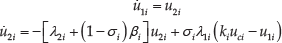
where u1 describes the position of actuator of each propeller and u2 represents the rate of change of the actuator. The coefficient of manoeuvrability, shown by
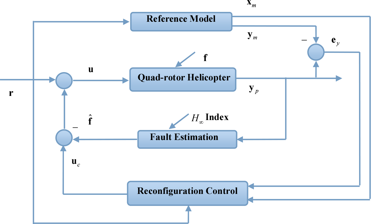
Reconfiguration control scheme for quad-rotor helicopter
4. Adaptive Reconfigurable Control Design
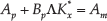
When the dynamic process of the system has some unknown faults, the parameters of the reconfigurable controller are modified automatically to achieve a better response. The following linear model of the quad-rotor helicopter with actuator faults is considered:

where

The actuator faults are described by the unknown matrices Λ, σ and vector
Equation (9) can then be regarded as the perturbation equation of the system in the equilibrium state.
Let

A linear reference model is selected as follows:

where
Here
A normal adaptive reconfigurable controller has the following form [30]:

where

where

Consider the matching conditions of the model of referring and we can define:


where
Some error matrices and vectors are given as follows:

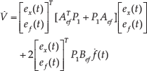
Substitute (16)∼(20) into (15) and we can finally derive the state error equation:
The following adaptive control laws are designed:


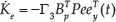

where weighting vectors

where Q is also a positive definite symmetric matrix.
Proof:
A positive definite Lyapunov function can be chosen in the following form:

Then the time-derivative of V is:
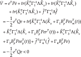
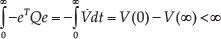
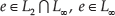
Therefore, the value of V is degressive; that is:

By integrating (29), we can obtain this:
5. Fault Observer Design
Fault estimation, conducted by adaptive observers, can obtain information about both the system state and faulty condition. The estimating error is surely made convergent to zero, while the convergence rate should be as high as possible. The
the rows of Cp have full rank;
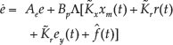
The following observer is designed for the faulty system:


where
The state estimation error and fault estimation error are defined as follows:


Then:


We can, therefore, construct the error system in this form:


in which case, the estimated error has the

where:


and
A positive Lyapunov function is chosen as:

while its derivative along system (40) is:
Define the following

then, according to (47), we can get

if
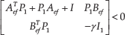
in which case, the performance index (48) can be obtained. Let


Definitions of
Finally, we derive the following:
Formula (42), then, is fulfilled.

where

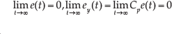
Meanwhile, we know that the estimated error is only associated with the variance ratio of fault, tracking index ratio and the initial estimated error, and is unrelated to the amplitude of fault according to Theorem 4.1.
6. Simulations and Experiments
6.1. Quad-rotor model parameterization
According to the descriptions in Section 2, general models of attitude and position can be constructed for the quad-rotor helicopter. In this paper, it is assumed that the helicopter works near the equilibrium position and coupling between attitude angles, while


where
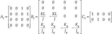

The main parameters associated with the quad-rotor model are given in the following table [25]:
Values of the model parameters

6.2. Numerical simulations
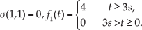
In the simulation, it is assumed that LIP takes place in the front propeller, while the fault occurs at 3s. The desired attitude angles (i.e., pitch, roll and yaw) are [0°, 0.4°, 0.9°], and the desired body-frame coordinates (i.e., X, Y and Z) are [0 m, 0.4 m, 4.6 m]. The fault can be presented as:
The related parameters are chosen as:
The gain matrices of the observer (33–35) for (56) are:

The gain matrices of the observer (33–35) for (57) are:
Meanwhile,

System response curves are respectively shown in Figure 3 and Figure 4, and the estimation curves of the fault can be found in Figure 5 (simulation time: 10s, 20s).

Attitude angles' responses under the proposed scheme

Position responses under the proposed scheme
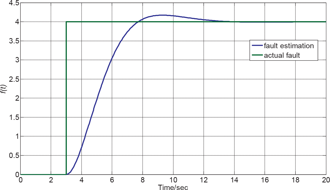
Estimation curves of actuator fault when
The curves in Figure 3 show that the desired flight performance can still be achieved under faulty conditions and that the convergent error goes to zero in a relatively short period of time. The position responses in Figure 4 demonstrate good reconfigurable ability of the proposed scheme. This implies that the quad-rotor helicopter can reach the predetermined position within 3s without any errors. Figure 5 indicates that the proposed fault observer (where
6.3. Experiments
The proposed method is also tested on the real-time simulation platform (called Qball-X4 of Quanser Company, see Figure 6) online [29].

Quanser Qball-X4
The Quanser Qball-X4 is an innovative rotary wing vehicle platform suitable for a wide variety of UAV research applications. The whole craft is enclosed within a protective carbon fibre cage, as seen in the Figure 6. The interface with the Qball-X4 is MATLAB Simulink with QuaRC, while the controllers can be developed in Simulink with QuaRC on the host computer. These models are then compiled into the executables on the target quad-rotor helicopter. In experiments, LIP faults occur in the front propeller when artificially restricting the input voltage of a forward motor to a fixed value. This can be achieved by updating parameters on the host computer. The experimental results are provided in Figure 7 and Figure 8.

Tracking errors of attitude angles (°) of the Qball-X4

Estimation curves of actuator fault tested on the Qball-X4
Some fluctuations in the experimental figures are unavoidable considering the non-linear components in the vehicle platform. However, the trend of these curves can still keep the flight trajectory steady and as desired on the Qball-X4. In addition, the fault estimation in Figure 8 can be approximately regarded as asymptotically convergent under the proposed scheme. For comparison, the adaption-based reconfiguration control method proposed by [33] is also tested on the platform (experiments on pitch angle and height) and contrastive curves are shown in Figure 9.

Tracking errors of pitch angle(°) and height(m) under different methods
Tracking errors need about 1∼2s to converge to zero and have some obvious oscillations during the dynamic process under the method designed by [33]. This causes the trembling of the quad-rotor helicopter in flight, which is sometimes unacceptable. Under the proposed scheme, however, fast tracking responses can keep the helicopter more secure and reposeful.
7. Conclusions
This paper has provided an improved reconfiguration control scheme for a quad-rotor helicopter with an actuator fault by applying the fault observer with an
Footnotes
8. Acknowledgements
The project was supported by the Aeronautics Science Foundation of China (2014ZC52033) and the National Natural Science Foundation of China (61533009, 61374130, 61473146), which is a project funded by the Priority Academic Programme Development of Jiangsu's Higher Education Institutions.