
Abstract
In this paper, we propose an application of an algorithm, based on the T-S (Takagi-Sugeno) technique, to stabilize a quadrotor helicopter. After giving the nonlinear model of the vehicle, its representation by a T-S fuzzy model is discussed. Following this, a fuzzy controller is synthesized, which will guarantee the stability of the quadrotor. The proposed T-S controller is designed with measurable premise variables and the conditions of stability are given in terms of linear matrix inequality (LMI). Simulations and real-time experiments using a test-bed platform prove the performance of a PDC control algorithm to stabilize the vehicle robustly at a desired set point.
Keywords
1. Introduction
Unmanned aerial vehicles (UAVs) have an important role for both military and civil purposes [1]. These underactuated vehicles feature a multivariable nonlinear dynamics, with a control system whose complexity depends on the requirements of the operation or mission. Therefore, many research groups have taken on the challenge of UAV development [2]. Modern UAVs are aerial robots capable of flying autonomously or semi-autonomously, with similar characteristics to conventional aircraft, and are categorized alongside other unmanned aircraft systems (UASs) [3]. UAVs have an autopilot on board to control the flight, establishing a bidirectional link with a ground station; this allows an on-land pilot to take decisions about the course and objectives of the flight [4]. One type of UAV that is frequently referenced nowadays in the control field is the quadrotor rotorcraft helicopter, known as the X4 helicopter, which has a greater manoeuvrability and thrust force (for lifting heavier weights) than other helicopters. According to [5], this type of helicopter achieves a stable hover flight through the balancing of the propulsion force exerted by the four rotors. The X4 is a vertical takeoff and landing vehicle (VTOL), able to move in 3D space and with the ability to fly in a stationary manner. It has four electric motors (see Figure 1), each one attached to a rigid cross frame. The front and rear rotors rotate counter-clockwise, while the left and right rotors rotate clockwise, thus cancelling out the gyroscopic effects and aerodynamic torques during stationary trimmed flight. Vehicle altitude is given by the sum of the thrust of each motor. Longitudinal/lateral motion is achieved by controlling the differential speed between the (front and rear)/(right and left) motors, tilting the X4-flyer around the (y -axis)/(x -axis) to generate a pitch/roll angle. The yaw angle is obtained by having two sets of rotors rotating in opposite direction, increasing or decreasing the speed of the front and rear motors while decreasing or increasing the speed of the lateral motors. The total thrust must be constant to maintain the desired altitude.

Schema of forces and moments
There have been many research works in the field of this type of vehicle; for example, some papers [6, 7, 8] have addressed the dynamical model, simulation and identification of parameters. The application of nonlinear control techniques, such as sliding mode and backstepping, can be found in [10, 11, 12] along with simulation or experimental results. A nested saturation control technique can be found in [13]; this technique was implemented in a PC-based platform, producing a satisfactory performance. The attitude stabilization problem is treated in [14] using a quaternion-based dynamical model with a Lyapunov function for a PD controller, and in [15], by calculating a robust margin. Observers and feedback controllers for controlling the attitude are proposed in [16] and [17]. The development of a fuzzy controller can be found in [18, 19, 20], where the nonlinear quadrotor model is represented using the Takagi-Sugeno (T-S) technique, resulting in a fuzzy representation of multiple models. A linear controller is then proposed to stabilize the vehicle, with results presented using numerical simulations. In this paper, we present a validation of the results obtained in [18] using a test-bed platform; the proposed fuzzy controller algorithm is embedded on a low-cost microprocessor. In addition, a more in-depth explanation of how to obtain the model and controller is given. This paper is organized as follows: in Section 2, we present the procedure for obtaining the quadrotor model, including rotor dynamics; Section 3 describes the main aspects of this fuzzy control approach; Section 4 gives a brief description of the architecture used in the test-bed platform; Section 5 presents the simulation results; Section 6 summarizes the experimental results; and finally, the conclusions are given in Section 7.
2. Attitude Subsystem from the Vehicle Flat-earth Model
The vehicle dynamic model can be obtained using the Newton Euler methodology; assuming that the vehicle evolved within a small local region, this will then result in the vehicle flat-earth model [21]. This model is described by the Equations (1) to (5), representing the kinematics, position, forces and moments.


In Figure 1, let
The attitude subsystem can be obtained using the Equations (3) and (5), where the term


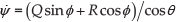
As can be seen in Figure 1, the X4 has two planes of symmetry, the

The term

where MT, MA and MG are the thrust, aerodynamic and gyroscopic moments. Using the matrix of inertia (9) and the moment vector (10) in Equation (5) yields the following:

The thrust moment is a result of the force components produced by each of the quadrotor's motors, and is expressed on the body frame. In the sense of pitch and roll, the thrust moment is calculated as the difference between the lift forces of each pair of rotors, on the same axis, multiplied by the distance l from each motor to the vehicle mass centre. In the sense of yaw, the thrust moment is the collective sum of the rotors' drag forces, also multiplied by l. The lift force

The aerodynamic moments are originated by the friction of the rotors (rotating) and the structure when the vehicle moves; these moments are quadratic functions of the vehicle angular velocity, expressed on the body frame. Thus,

where
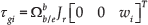
The total gyroscopic moment is the sum of these individual moments:
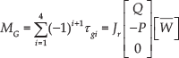
where

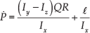
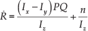
Hence, considering all the above and substituting into Equation (10), the model (11) to (13) yields the following:
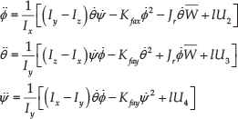
where the system control inputs are Ui,

2.1. Nonlinear State-space Representation
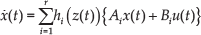
For convenience, the system (19) can be expressed in a nonlinear state space of the form


with the following suitable state, output and input vectors:

and state matrices:

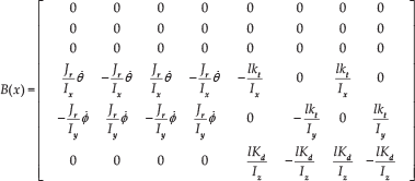

3. Takagi-Sugeno Fuzzy Representation
The nonlinear system can be represented using the Takagi-Sugeno approach, using a number of fuzzy IF-THEN rules.
3.1. T-S Fuzzy Model
We have chosen the following measurable premise variables:

In our previous work [18], the design for the fuzzy model was presented assuming that angular velocity variation occurs between the minimum and maximum values:

Thus, the following IF-THEN rules can be considered:

where
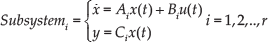
with r=8 subsystems.
This allows the nonlinear model (21) to (22) be represented by eight local LTI models. The complete T-S fuzzy model for the

with
where the activation functions are

with

3.2. T-S Fuzzy State-feedback Controller
In designing a fuzzy controller, we utilize the parallel distributed compensation (PDC) technique to stabilize the T-S fuzzy system. The fuzzy controller shares the same fuzzy sets as the fuzzy model.
The fuzzy state-feedback is represented as follows:

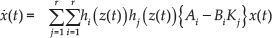
Thus, the closed-loop T-S fuzzy model becomes
The controller is designed such that the closed-loop fuzzy system is asymptotically stable; therefore, the fuzzy state controller is required to satisfy the following:

A sufficient quadratic stability condition for ensuring the stability of (27), derived from [22] and [18], is given as follows:

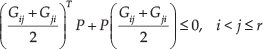
where
The determination of gains


where
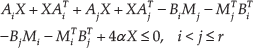
Different control performances can be represented in terms of LMI. It is important to consider the speed as well as the stability of response; our study is based on results from [22]. The speed of response is related to the decay rate, i.e., the largest Lyapunov exponent. The condition that

where
maximize α when:


where
We are now able to determine the gains
From Theorem 1, we can verify the robustness property of the controller, since stability is satisfied for each subsystem in the multi-model scheme. This represents the vehicle operation range.
4. Experimental Platform Description
In this section, we describe the hardware and software architecture used to build the onboard system, which allows the quad-rotor helicopter experimental platform to be stabilized. The system architecture includes a microcontroller (MBED), an inertial measurement unit (IMU), and a wireless modem.
4.1. Hardware
The autopilot system uses the low-cost MBED microprocessor (NXP LPC1768) as its main processor, which has an execution speed of 96MHz and a 32-bit architecture, as well as 32KB of RAM and 512KB of FLASH memory. The processor is powered using a 5V USB or using an external supply (4.5 to 9V) applied to the VIN pin, and includes a built-in USB programming interface, which is as simple to use as a USB Flash Drive. The processor comes in a module along with a wide variety of devices, such as an integrate USB bus, three serial ports, one CAN bus, one Ethernet port, six PWM outputs, general purpose ports, and six analogue input channels. In addition, the modules are small in size and are supplied in a 40-pin DIP package (54×26mm). The MBED microprocessor is programmed using a C-language development system, using a website lightweight online compiler for developers. Figure 2 shows the autopilot architecture block diagram. The autopilot system use a microcontroller that directly determines the position and angular velocity from the inertial MTi Xsens unit, and receives the remote-control commands or set points through the wireless modem via a serial port. The modem used is the XBee-PRO, which is very stable if the distance is less than 100 metres. This distance is enough for an indoor test-bed platform. The microcontroller calculates the control law and sends the correction through the IIC port to each motor driver. Through analogue channels, the position data

Quad-rotor electronic onboard schema

Program state machine scheme
4.2. Software
The software program executes several functions, such as reading sensors and calculating control laws, in order to stabilize the aerial vehicle. This program was developed taking the state machine architecture as its main schema, which is represented by the functional diagram shown in Figure 4. This architecture runs in two phases. The first phase is executed only once, to set and initialize all the variables and registers that are used during the program execution. In the second phase, the main loop takes place, which is dedicated to calculating the control law, and reading the IMU and remote control via serial channels, using interrupt service routines. These routines must be as short as possible in order to improve the program performance. Once the control law has been calculated with the current data from the IMU and RC, correction signals are sent to each motor driver to change the speed. Another activity that is executed periodically is linking with the ground station; this can be done using a wireless modem, or using the USB programming port in debug mode.

Control law algorithm main steps
The main steps of the control law algorithm function implemented in the microcontroller are shown in figure 4.
5. Numeric Simulation
Before implementing the control algorithm in the experimental platform, a numerical simulation was conducted using MATLAB Simulink. A simplified block diagram of the closed-loop system simulation is shown in Figure 5, in which the control law algorithm can be found on the block labelled “multi-model state feedback”. The quadrotor nonlinear model block has as its input the vector

Dynamic model implemented in Simulink
In order to determine the parameters, an experimental identification was performed to obtain the thrust and drag coefficients, Kt and Kd, using as data the force and angular velocities of the rotors. Other parameters were taken from the bibliography [8], in order that both vehicles would have similar dimensions. Table 1 summarizes the main parameters. The simulation results of the T-S fuzzy state-feedback controller are shown in figure 6. The source code of this scheme can be found in MATLAB Central (visit http://www.mathworks.com/matlabcentral/fileexchange/53711-x4-multimodel-control). The state variables were initialized with values of 25 degrees for the pitch, 20 degrees for the roll and 15 degrees for the yaw, with a desired value of zero for all of the variables. As the simulation continued to run, all the output variables converged to zero and remained at this value, giving a satisfactory performance.
Quadrotor helicopter parameters


Simulation results of the angles
6. Experimental Results
This section presents the experimental results obtained with the quadrotor helicopter platform, which is shown in Figure 7. It consists of the embedded autopilot system, which is an inexpensive architecture that could be built by someone with minimal experience in electronic circuit design. The experiments were only used here to validate the vehicle's angular position or attitude in safe mode; however, they could also be used to validate linear position. The mechanical chassis of the experimental platform consists of four rotors mounted in a frame taken from the Reely 450 RC helicopter. The platform is mounted in a fixture that allows it to rotate and move in x and z directions freely, with the follow limits:

The quad-rotor experimental platform
Figure 8 shows the response of the control system with the initial conditions for the pitch

Experimental attitude stabilization response using the fuzzy state-feedback controller
Additionally, the response for a PD controller is shown in Figure 9, so that the behaviour of the proposed state-feedback controller can be compared with that of the PD controller. Note that, with this control algorithm, the attitude value was not able to converge to zero. This makes sense because, in the proportional action, there exists an offset with respect to the desired value. Furthermore, the derivative action is sensitive to the angle measurement noise, due to mechanical vibrations.

Experimental attitude stabilization response using the classic PD controller
Figure 10 shows the angular velocity response, which always converges to the values

Angular velocity response with the fuzzy state-feedback controller
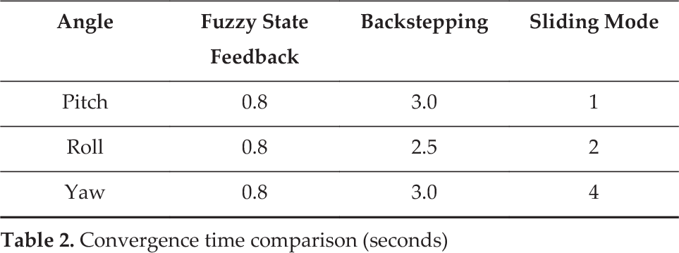
It should be acknowledged that these results concern the stability problem around the origin. If the output states were to be set to a desired value different than zero, the stability problem would become a regulation problem; this could be studied in future work. Table 2 shows a comparison of the state convergence time, to the desired zero value, using the fuzzy state feedback proposed here, with respect to the time using the backstepping and sliding mode controllers [10].
Convergence time comparison (seconds)
7. Conclusions
In this paper, we have presented the implementation of a fuzzy control in a real-time embedded system, to validate its performance. The development of a low-cost architecture for the experimental platform was also described. The T-S fuzzy approach, along with a fuzzy controller scheme for the stabilization of the vehicle, was proposed. The nonlinear model was obtained and represented in a nonlinear state form, in order to use it for the T-S fuzzy model representation. A fuzzy state-feedback controller was thus obtained. Using numerical simulations, we were able to show that the controller can ensure all states converge to zero, when
Footnotes
8. Acknowledgements
The authors would like to thank the Université de Picardie Jules Verne, France, the Autonomous University of Tamaulipas, Mexico, and the Mexican Council of Science and Technology (CONACYT) for their support of this work.