
Abstract
This paper proposes a hand-eye LRF-based (laser range finder) welding plane-detection method for autonomous robotic welding in the field of shipbuilding. The hand-eye LRF system consists of a 6 DOF manipulator and an LRF attached to the wrist of the manipulator. The welding plane is detected by the LRF with only the wrist's rotation to minimize a mechanical error caused by the manipulator's motion. A position on the plane is determined as an average position of the detected points on the plane, and a normal vector to the plane is determined by applying PCA (principal component analysis) to the detected points. In this case, the accuracy of the detected plane is analysed by simulations with respect to the wrist's angle interval and the plane angle. As a result of the analysis, an iterative plane-detection method with the manipulator's alignment motion is proposed to improve the performance of plane detection. For verifying the feasibility and effectiveness of the proposed plane-detection method, experiments are carried out with a prototype of the hand-eye LRF-based system, which consists of a 1 DOF wrist's joint, an LRF system and a rotatable plane. In addition, the experimental results of the PCA-based plane detection method are compared with those of the two representative plane-detection methods, based on RANSAC (RANdom SAmple Consensus) and the 3D Hough transform in both accuracy and computation time's points of view.
1. Introduction
Welding operations have been required in various manufacturing industries, such as car and shipbuilding, among others [1]. Since productivity and the quality of the products can be remarkably improved if welding operations are automated, extensive research about autonomous robotic welding has been carried out. As a result, most welding operations in automotive assembly lines have already been automated. On the other hand, welding operations in the shipbuilding industry have been far less automated because of its large-scale and unstructured production environment. Thus, more studies about autonomous robotic welding are still required in the field of shipbuilding.
General robotic welding consists of two steps, such as welding-target recognition and autonomous welding along the welding path, which is predefined by the CAD (Computer Aided Design) model of the welding target. In this case, welding-target recognition is a very important factor that determines the success or failure of the autonomous robotic welding. Thus, much research about welding-target recognition has been conducted by using various kinds of sensors, such as a vision, a structured-light vision and an LRF (laser range finder), among others. In the case of using a vision [2], the computational complexity for target recognition increases remarkably, since a lot of image-processing steps, such as binary thresholding, edge detection, labelling and pattern matching, are needed for robust target recognition. In the case of using a structured-light vision [3–6], the computational complexity is relatively less complex than that of a vision, but it is still quite high. In addition, the size of the sensor is larger than that of a vision, since a structured-light source should be added to a vision. In our previous work [7], a structured-light vision is also proposed for welding-target recognition. In this case, as many as four laser sources are used with a monocular camera. Since it is sometimes possible to constrain the motion of the welding robot in a case where the sensor is not compact, the sensor must be designed to be as compact as possible. Conversely, in the case of using an
In the field of shipbuilding, most welding operations consist of welding huge steel plates together, and attaching steel plates to parts such as lugs; a lug is a kind of handle used to move a steel plate. As mentioned above, a welding robot should detect welding targets precisely for successful autonomous welding. In this paper, we also focus on welding-target recognition, especially steel-plate recognition. In this case, the steel plate is modeled as a plane which can be defined by its position and normal vectors. In various fields of research, a considerable number of studies have been conducted on plane detection. Most plane-detection methods that have been proposed are based on three representative methods, such as the 3D Hough transform, RANSAC (RAndom SAmple Consensus)[13] and PCA (principal component analysis). In [14], in order to obtain planes, the 3D Hough transform is applied to a continuous point cloud stream generated by a depth sensor over time. The obtained planes are iteratively refined for robust plane detection. The 3D Hough transform originally requires high memory for the parameter space and computational complexity of point accumulations. For reducing the memory requirement and computational complexity, the hierarchical structure is used and tune up experimentally, and a cache space is used, respectively. In [15], the 3D Hough transform and RANSAC are used for automatic detection of 3D-building roof planes from LIDAR data. In this case, RANSAC is more efficient than the 3D Hough transform regarding computation time and quality. In [16], the 3D plane-based map building method is proposed for mobile robot navigation. For plane detection, the 3D Hough transform and RANSAC are used; the plane acquisition times for them are 50ms and 170ms, respectively. In this case, RANSAC is also better than the 3D Hough transform. The generated planer map of the environment is stored in an Octree-based data structure. In [17], the surface elements are first grouped by the 3D Hough transform, and then the best plane is fitted by RANSAC. For efficient use of the available data, a multiresolution approach based on a coarse-to-fine strategy is used. In [18], the plane is detected by PCA after outliers are removed by using the robust scatter matrix, since PCA is very sensitive to outliers. From the experimental results, the proposed method is significantly better than RANSAC in terms of time, accuracy and robustness. According to the results addressed above, in most cases, use of PCA for plane detection in 3D space is better than both the 3D Hough transform and RANSAC. Thus, we used PCA for plane parameter acquisition.
In this paper, a scanning LRF is attached to the wrist of a 6 DOF welding manipulator for steel-plate recognition. Since the LRF data are not sufficient for recognizing the target plate, more data are obtained via the wrist's rotational motions. The plane parameters, such as position and normal vectors, are calculated by using the obtained LRF data. The position vector is defined as an average position of the detected points, and the normal vector is calculated by applying PCA to the detected points. For improving the feasibility and effectiveness of plane detection, the error of the normal vector is first analysed by simulations with respect to the change of the wrist's angle interval and the detected plane angle, considering the intrinsic characteristics of the LRF [19, 20]. According to the results of the error analysis, the number of the wrist's rotations can be reduced as far as possible for rapid detection. In addition, for improving accuracy, an iterative plane-detection method with alignment motions of the manipulator is proposed[21]. After alignment motions, the laser beams of the LRF are nearly perpendicular to the plane, and the number of outliers affected by noise can be remarkably reduced. Thus, PCA can work well, although it is very sensitive to the LRF data's outliers. Finally, the results of PCA are compared with two representative plane-detection methods, such as the 3D Hough transform and RANSAC, with respect to accuracy and computation time.
The organization of this paper is as follows. In Section 2, the hand-eye LRF-based robotic welding system is proposed, and the frames for the manipulator and the sensor are defined. In Section 3, the PCA-based plane detection method is proposed, and its accuracy is analysed with respect to the change of the wrist's angle interval and the plane angle. According to the results of the analysis, the iterative plane-detection method for improving accuracy and reducing acquisition time is proposed by using the manipulator's alignment motions. Section 4 introduces the experimental set-up with the prototype of the hand-eye LRF system, consisting of a 1 DOF wrist joint, an LRF sensor and the rotatable plane. Next, experimental results are shown for verifying the feasibility and effectiveness of the proposed plane-detection method based on PCA. In addition, the comparison results with two representative plane-detection methods based on RANSAC and the 3D Hough transform are given. Finally, Section 5 presents concluding remarks.
2. Hand-eye LRF-based Robotic Welding System
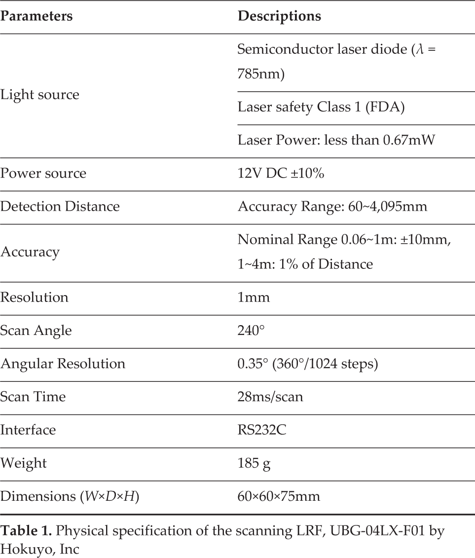
In this section, we propose a hand-eye LRF-based robotic welding system as shown in Fig.1. The welding robot has a welding torch on its end-effector and a scanning LRF on its wrist for precise steel-plate detection. The scanning LRF used in this paper is UBG-04LX-F01 by Hokuyo, Inc., which can detect distances using the rotational motion of a laser beam. The physical specifications of UBG-04LX-F01 are shown in Table 1.
Physical specification of the scanning LRF, UBG-04LX-F01 by Hokuyo, Inc
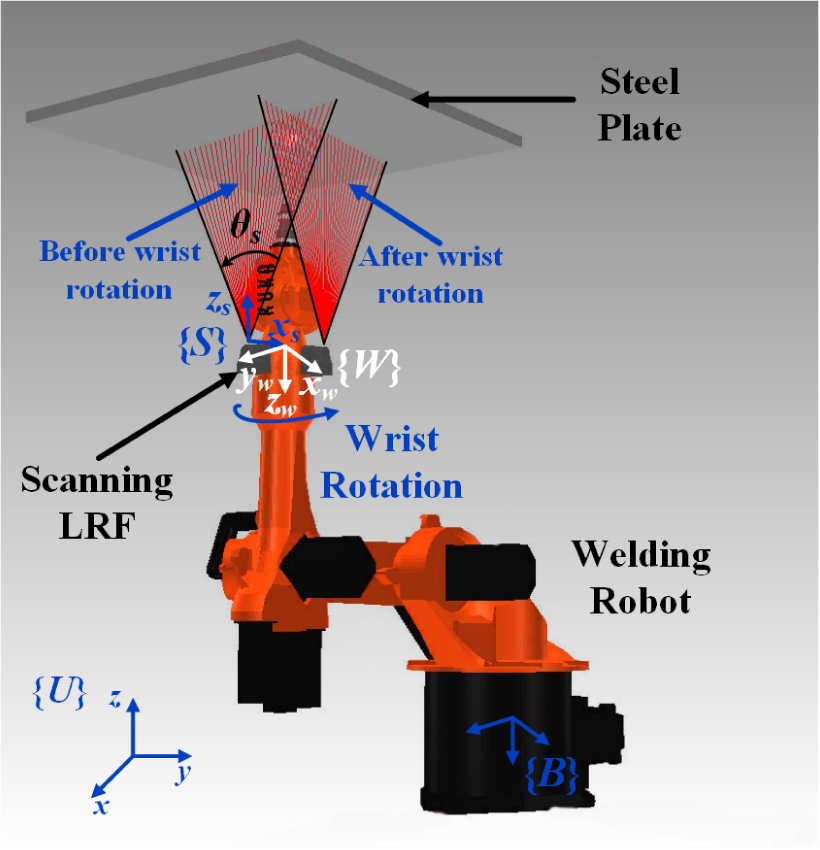
Hand-eye LRF-based 6 DOF welding robot which has an LRF on its wrist
For representing LRF data, coordinate frames for the manipulator and the LRF sensor are first defined with respect to the universal frame {U}, which is a reference coordinate frame as shown in Fig.1. The fixed-base frame and the wrist frame of the manipulator are described as {B} and {W}, respectively. The LRF sensor frame is described as {S}. The homogeneous transformation matrix B S T from {B} to {S} can be obtained via Eq.(1).

where BWT can be obtained by the forward kinematics of the manipulator and WST is known from design parameters of the hand-eye LRF sensor. Although the scanning angle is 240° with the angular resolution of 0.35°, a scanning angle of only θ
s
from

where [0 0 di1] T is the ith distance vector in the direction of the laser beam. By BST in Eq.(1), SPi can be represented with respect to {B} in Eq.(3).

In this way, the distances to the points on the plane can be represented with respect to {B}. However, the plane cannot be determined by only one set of the distance data since all detected points of the scanning LRF are collinear on the plane. Thus, we need more than one set of the distance data to the points, not all of which are collinear. In this paper, we obtain more than one set of the distance data through the rotational motion of the wrist, where the wrist is repeatedly controlled and rotated by the interval angle Δθ w between two consecutive data sets. Therefore, the number of the sets is determined as m = 360° / Δθ6w. Consequently, m sets, each of which consists of k distance data, are used for plane detection. From here, the total number of the distance data detected by the hand-eye LRF is defined as n = m × k.
3. Precise Plane Detection
3.1 PCA-based Plane Detection
The huge steel plates used for shipbuilding are modeled as a plane, which is determined by a normal vector to the plane and a point on the plane. The normal vector is obtained by applying PCA to the points Pi(xi,yi,zi) for i=1,…,n detected by the hand-eye LRF, and the point is determined as the mean of the detected points. First, a n × 3 matrix

where the means, X̅, Y̅ and Z̅, for three dimensions are defined from Eq.(5) to Eq.(7).


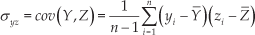
From Eqs.(5), (6) and (7), the position vector P̂m of the point on the plane is first determined as (X̅, Y̅, Z̅). Next, the covariance between two dimensions for X and Y can be obtained based on Bessel's correction in Eq.(8).

where σ xy is equal to σ yx , since the covariance satisfies the commutative law. In the same way, the covariances σ yz and σ zx can be defined in Eqs.(9) and (10), respectively.

In this case, the covariance between one dimension and itself is the variance. For each dimension, the variance is obtained from Eq.(11) to Eq.(13).


From Eq.(8) to Eq.(13), the covariance matrix C can be defined as shown in Eq.(14).

where C is a 3×3 square matrix. The eigenvalue λ and the eigenvector V for the covariance matrix C can be obtained from Eq.(15).

where three eigenvalues are obtained, and all eigenvectors for them are mutually perpendicular (or orthogonal). The eigenvector with the largest eigenvalue indicates the direction with the highest variance of the detected points on the plane, and each succeeding eigenvector in turn indicates the direction with the next highest variance, under the constraint that it is orthogonal to the preceding vectors. Let Vi for i=1,2,3 be the eigenvector corresponding to the eigenvalue λ i , where λ3 ≥ λ2≥λ1≥0. In this case, two eigenvectors, V3 and V2, corresponding to the two largest eigenvalues, λ3 and λ 2 , lie on the plane and are orthogonal to each other, since the detected points are scattered only on the plane. Thus, we can find the right vector of the plane as the eigenvector V1 corresponding to the third eigenvalue λ1, since V1 is orthogonal to both V3 and V2, which are the basis of the plane. In this way, the normal vector to the plane and the point on the plane can be obtained.
In Fig. 2, the simulation results for the PCA-based plane detection method at a distance of 800mm are shown. Since the distance to the plane is 800mm, we added random noise ranging from −10mm to +10mm to the detected distances of the LRF, taking the accuracy of the LRF in Table 1 into consideration. In this case, the scanning angle θ S is set as 40°, and the distance d between the wrist's rotational axis and the central axis of the LRF is set as 115mm. Thus, the number of points, k, for one scanning data set is 114 (= 40° /0.35°), where the angular resolution of the LRF is 0.35°. The wrist's roteitional angle Δθ w is set as 10°, and thus the number of the scanning data sets, m, is 36 (= 360° / 10°). Therefore, the total number of the detected points, n, is 4004 (= 36 × 114). By applying PCA to the points, n, is 4104 (= 36 × 114). By applying PCA to the detected points, the normal vector to the plane can be obtained as the eigenvector V1 corresponding to the smallest eigenvalue λ1 among three eigenvalues, where the eigenvectors V3 and V2 corresponding to the two largest eigenvalues λ3 and λ2, respectively, lie on the plane and are orthogonal to V1. In this case, the point on the plane is determined as the mean vector P̂m of the whole of the detected points.

Simulation results for plane detection according to the plane angle of θ p
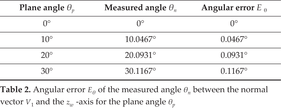
In Fig. 2, for ease of understanding, the coordinate frame {W} is depicted as the wrist frame where there is no rotation of the wrist, although the actual frame {W} is changed depending on the wrist's motion. From Fig. 2(a) to Fig. 2(d), the results of plane detection are shown according to the change of the plane angle θ p from 0° to 30°. In the figures, three eigenvectors, V3, V2 and V1, corresponding to the eigenvalues λ3, λ2 and λ1, respectively, are depicted, where λ3 ≥ λ2 ≥ λ1. The first two eigenvectors, V3 and V2, lie on the plane although their directions change according to the distribution of the detected points. Thus, we can obtain the normal vector to the plane as V1, since V1 is orthogonal to both V3 and V2. Using the normal vector V1, the plane angle is measured as the angle θ n between V1 and the zw -axis. In Table 2, the angular error Eθ of the measured angle θ n is less than 0.1167° for the plane angle θ p from 0° to 30°. Thus, the normal vector to the plane can be obtained by PCA with a reasonably small error for plane detection. However, the error Eθ tends to increase as the plane angle θ p increases.
Angular error Eθ of the measured angle θn between the normal vector V1 and the zw -axis for the plane angle θp
3.2 Iterative Plane Detection with Alignment Motion of the Manipulator
In Sec.3.1, the angular error Eθ is reasonably small for plane detection, but it tends to increase as the plane angle θ p increases. In this section, the relationship between the plane angle θ p and the angular error Eθ is analysed, and an iterative plane-detection method is suggested for precise plane detection. In Fig.3, the simulation results for plane detection with the wrist's rotational angle Δθ w of 30° are shown. The relationship between the plane angle θ p and its maximum (or upper bound) error (| Eθ | + σθ) is shown in Fig. 3(a), where Eθ is the average angular error and σθ is its standard deviation. As shown in Fig. 3(a), (| Eθ | + σθ) increases as θ p increases. If the tolerable error ET for successful autonomous welding is set as 0.04°, the normal vectors for θ p = 10°, 20°, 30° are not suitable for autonomous welding since their errors are greater than ET. From the plane angle's point of view, if the measured angle θ n for the normal vector is greater than θ ref , corresponding to the tolerable error ET, the robotic welding is quite likely to fail, where θ ref is determined as 7.782°, as shown in Fig. 3(b), which is a magnification of part A in Fig. 3(a). In the case that θ n is greater than θ ref , the additional alignment motion of the manipulator is required to reduce the plane angle θ p close to zero, and then the normal vector to the aligned plane is again detected by the hand-eye LRF, where the alignment motion is to align the zm -axis parallel with the detected normal vector. In this case, we have to consider the mechanical error Em caused by the manipulator's alignment motion. If we assume the manipulator has a relatively large error Em= 3°, then the aligned plane angles for given θ p = 10°,20°,30° after alignment motion are measured as ①, ② and ③, respectively, in Fig. 3(b). Although the plane angles of ①, ② and ③ about the θ p axis are slightly greater than 3 because of Em, they are sufficiently smaller than θ ref . Thus, the aligned plane can be detected with an error less than ET by conducting one more measurement of the hand-eye LRF. In the simulations, the plane can be detected precisely by only two measurements of the hand-eye LRF. However, the second measurement may in reality have an error greater than ET. In this case, two steps, such as manipulator alignment and LRF measurement, are carried out iteratively until the measured angle θ n is less than θ ref , as shown in Fig.4. In this way, we can find the normal vector to the plane with an error less than ET.

Relationship between the maximum (or upper bound) angular error | Eθ | + σθ of the normal vector V1 and the plane angle θ p , where Eθ is the average error and σθ is its standard deviation
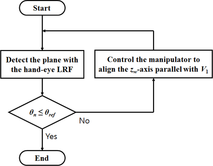
Flowchart of iterative plane detection
3.3 Error Analysis for Rotational Angle of the Wrist
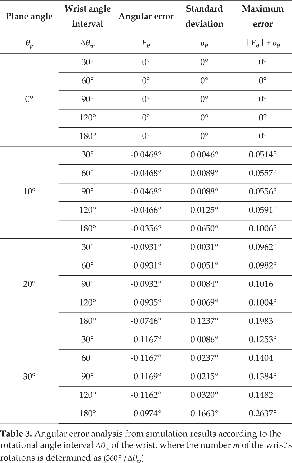
In Sec.3.1 and Sec.3.2, the wrist's rotational angle Δθ w is set as 10° and 30°, respectively, thus obtaining 36 and 12 distance data sets. In this case, the amount of distance data is large enough to detect the plane but it is still very inefficient, because as many as 35 or 11 rotational motions of the wrist are additionally required. In this section, we want to reduce the number of the wrist's rotations for improving the efficiency of the proposed method. The number of rotations is determined as m-1, where m is the number of data sets and is determined by the wrist's rotational angle interval Δθ w as (360° / Δθ w ). In other words, we want to increase Δθ w as much as possible. In Table 3, the simulation results of plane detection for θ p = 0°, 10°, 20°, 30° are shown with respect to the change of Δθ w from 30° to 180°. While the average angular error Eθ for each wrist's angle interval Δθ w tends to increase as the plane angle θ p increases, Eθ for each θ p has no significant change as Δθ w increases. That is because the variance of points about the second-largest principal axis decreases as θ p increases, while that about the largest principal axis increases. In this case, the accuracy of the calculated direction of the second-largest principal axis decreases, and Eθ increases consequentially. On the other hand, as Δθ w increases, the ratio of the variances about the first and second principal axes is not changed significantly, although the number of points decreases. Thus, there is no significant change of Eθ although Δθ w increases. Next, the larger Δθ w is more sensitive to θ p than the standard deviation σθ is. That is because the total number of points decreases as Δθ w increases. If the number of points is small, the efficiency of noise cancellation by using PCA is much reduced. As a result, σθ increases as Δθ w increases. For consideration of both Eθ and σθ, the maximum (or upper bound) error is defined as (| Eθ | + σθ), and tends to increase as θ p or Δθ w increases. If the tolerable error ET is 0.04°, as in Sec.3.2, the measurement results are not reliable, except for θ p = 0°, since their errors are greater than ET. In this case, the alignment motion of the manipulator is needed to reduce θ p close to zero. If the mechanical error Em of the manipulator is set as 3°, as in Sec.3.2, θ p is slightly larger than 3° but is smaller than 3.2637° in the worst-case scenario for θ p = 30° and Δθ w = 180° after alignment motion. Thus, the error (| Eθ | + σθ) can be remarkably reduced in the second measurement of the LRF.
Angular error analysis from simulation results according to the rotational angle interval Δθw of the wrist, where the number m of the wrist's rotations is determined as (360°/Δθw)
For example, the maximum error (| Eθ | + σθ) for the plane angle θ p is shown in Fig.5, where the wrist's angle interval Δθ w is set as 180°. As shown in Fig.5(a), (| Eθ | + σθ) monotonically increases as θ p increases. In Fig.5(b) which is the magnification of part A in Fig. 5(a), the reference plane angle θ ref for the tolerable angle ET is determined as 3.976°. For θ p = 10°,20°,30°, the aligned plane angles after the manipulator's alignment motion are smaller than ①, ② and ③ about the θ p axis, respectively. In this case, only the second measurements of the LRF are reliable, since ①, ② and ③ are all smaller than θ ref . Of course, ①, ② and ③ about the (| Eθ | + σθ) axis are smaller than the tolerable error E T . Consequently, the wrist's angle interval Δθ w of 180° is large enough to measure the plane precisely using the iterative plane-detection method under the constraints of ET =0.04° and Em = 3°. Since Δθ w is 180°, the number of the wrist's rotations can be reduced to one. Although the results of plane detection depend on ET and Em, reliable results can be obtained by the iterative plane-detection method with just one rotation of the wrist in the simulation results.

Simulation results for Δθ w = 180
4. Experiments
4.1 Experimental Set-up
For verifying the feasibility and effectiveness of the proposed plane-detection method, an experimental set-up consisting of a prototype of the hand-eye LRF and a rotatable plane was devised, as shown in Fig.6. In Fig. 6(a), the prototype of the hand-eye LRF consists of two parts, such as a 1 DOF wrist joint and an LRF sensor system. In this case, the wrist joint consists of a motor, a motor controller and a motor battery. The motor controller is connected to the control computer via the RS-232 serial communication. Also, the LRF sensor system consists of an LRF sensor and a power supply. The LRF sensor is also connected to the control computer via the RS-232 serial communication. Therefore, the control computer can not only control the motor but also receive the LRF sensor data. Using the received LRF data, the control computer detects a plane with 3.3 Ghz quad core CPUs and 8 GB of RAM. In the experimental set-up, the vertical and horizontal positions of the hand-eye LRF can be changed manually. In this case, the motor can be controlled only from 0° to 300°, unlike the simulation from 0° to 360°, because of the configuration of the prototype. Thus, the number of the LRF data sets, m, is determined as ((300° / Δθ w ) + 1) in the experiments. In the bottom part of the experimental set-up, there is a plane whose angle can be manually changed. Thanks to the plane with the changeable angle, the experiment for plane detection can be carried out, taking the aligned motion of the manipulator into consideration. The sensor frame {S} and the wrist frame {W} are defined as shown in Fig. 6(b), where the distance d between the origins of {S} and {W} is set as 68.7mm. The xw -axis and the xs -axis are initially aligned parallel to the rotational axis of the plane. The distance between the origin of {W} and the rotational axis of the plane about the zw -axis is set as 580mm.
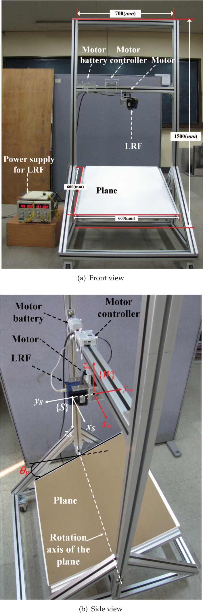
Experimental set-up with the prototype of the hand-eye LRF
4.2 Experimental Results for the PCA-based Plane Detection
Using the experimental set-up in Sec.4.1, the experiments on plane detection for θ p = 0°,10°,20°,30° are carried out with respect to the change of Δθ w from 30° to 180°, as shown in Table 4. Both the average angular error Eθ and the standard deviation σθ for the Δθ w of the wrist increase monotonically as the plane angle θ p increases, as in the simulation results. However, both Eθ and σθ for each θ p do not increase monotonically, but tend to increase as Δθ w increases. Similarly, the maximum error (| Eθ | + σθ) for each Δθ w increases monotonically as θ p increases, while (|Eθ | + σθ) for each θ p does not increase monotonically, but tends to increase as Δθ w increases. For verifying the feasibility of the iterative plane-detection method, experimental results for Δθ w = 30° and 180° are analysed in Fig.7 and Fig.8, respectively, where the tolerable error ET and the mechanical error Em of the manipulator are set as 1.5° and 3°, respectively. Although the mechanical error of the actual manipulator for autonomous welding is much less than that of 3°, as in [22], the error Em is defined as 3° in consideration of the worst-case scenario.
Angular error analysis from experimental results, according to the rotational angle interval Δθw of the wrist where the number m of the wrist's rotations is determined as ((300°/Δθw)+1)


Experimental results for Δθ w =30°

Experimental results for Δθ w = 180 °
For the wrist's angle interval Δθ w = 30°, the experimental results about iterative plane detection are shown with respect to the change of the plane angle θ p in Fig.7. As shown in Fig. 7(a), the maximum error (|Eθ | + σθ) monotonically increases as the plane angle θ p increases. When the laser beam of the LRF is parallel to the normal vector to the plane, the distance error is the smallest probabilistically. The number of laser beams which are parallel or subparallel to the plane's normal vector is larger in the case of the level plane than in the case of the inclined plane. As a result, the smaller θ p is, the smaller (|Eθ | + σθ) is. Since the maximum errors except for θ p = 0° are greater than the tolerable error ET, the manipulator's alignment motion is needed to reduce the plane angle close to zero. Since the reference angle θ ref corresponding to ET is determined as 7.21° as shown in Fig. 7(b) which is the magnification of the part A in Fig. 7(a), the plane detection and the alignment motion should be conducted iteratively until the aligned plane angle θ p is less than or equal to θ ref .. The aligned plane angles for the initial plane angle θ p = 10°,20°,30° are denoted as ①, ② and ③ about the θ p axis respectively. In this case, ①, ② and ③ are less than θ ref and their maximum errors are also less than ET. Therefore, the second measurement of the LRF after just one alignment motion is enough to precisely detect the plane with an error less than the tolerable error ET.
Next, for Δθ w = 180°, the experimental results for iterative plane detection are shown with respect to the change of θ p in Fig. 8. As shown in Fig. 8(a), the maximum error (|Eθ | + σθ) monotonically increases as θ p increases. Similar to the case of Δθ w = 30°, the smaller that θ p is, the smaller Eθ is. Since the maximum errors, except for θ p = 0°, are greater than ET, similar to the results for Δθ w = 30°, the manipulator's alignment motion is needed to reduce the plane an angle close to zero. Since the reference angle θ ref with respect to ET is determined as 4.316°, as shown in Fig. 8(b), which is the magnification of the part A in Fig. 8(a), the plane detection and the alignment motion should be conducted iteratively until the aligned plane angle θ p is less than or equal to θ ref . The aligned plane angles for the initial plane angle θ p = 10°,20°,30° are denoted as ①, ② and ③ about the θ p axis, respectively. After the first alignment motion, the plane angles ①, ② and ③, are 4.9123°, 6.2316° and 7.3030°, respectively, and their maximum errors are 1.5435°, 1.6391° and 1.7168°, respectively. Since the aligned plane angles after the first alignment motion are greater than θ ref , one more alignment motion is needed. After the second alignment motion, the aligned plane angles for ①, ② and ③ will be 4.5435°, 4.6391° and 4.7168°, respectively, and they are still greater than θ ref . Thus, we can consider that one more alignment motion is needed. However, in this case, additional alignment motions are useless for reducing the plane angle close to zero. Since the mechanical error Em is 3°, the maximum error of the aligned plane angle should be less than 1.316° in order to obtain the plane angle with an error less than ET after one more alignment motion. In this case, the maximum error less than 1.316° is achieved for the plane angle less than θ ref , but the aligned plane angle is greater than θ ref after additional alignment motions. Thus, we cannot detect the plane precisely when under the constraints of Δθ w = 180°, ET =1.5° and Em=3°. To resolve this problem, we have to reduce the wrist's angle interval Δθ w , even though the number of the wrist's rotations increases or replaces the manipulator with the mechanical error Em of 3° with another that has a smaller mechanical error. In this way, we can determine the wrist's angle interval and the specification of the manipulator in order to satisfy the requirements of successful autonomous robotic welding.
4.3 Comparison with RANSAC and 3D Hough Transform-based Plane-Detection Methods
Using the experimental set-up as in Sec.4.1, a comparison between the PCA-based plane-detection method in Sec.4.2 and two other representative methods were conducted. One is the RANSAC-based (RANdom SAmple Consensus) plane detection method, and the other is the 3D Hough transform-based plane-detection method. RANSAC is a randomized procedure that fits an accurate model iteratively to observed data without trying all possibilities[13]. For plane detection, three points are extracted randomly from the detected points on the plane, and used to compute the plane model's parameters. The obtained model's suitability for the remaining points is assessed via a score function. The score is determined by reference to the number of points that are close enough to the obtained plane. After the above process from three random point-extraction is carried out iteratively, the plane model with the best score is taken to be the winner. In this case, the threshold value of the distances to the closest points and the number of iterations should be appropriately determined for precise and fast detection. The threshold value is determined as 2σ, where σ is the standard deviation of the points. The points within the threshold value are defined as inliers and their percentage is about 95.5% in a normal distribution. The points outside the threshold value are defined as outliers. Since the points with random noise are probably included in outliers, the effects of the random noise can be reduced. For determining the number of iterations, N, the probability of a successful detection is first considered as P = 1 - (1 - α
m
)
N
, where α is the percentage of inliers and m is the number of extracted random points [23]. Thus, N can be obtained as
Next, the Hough transform is one of the popular parameter-estimation methods based on a voting mechanism. For plane detection, the original Hough transform proposed for line detection should be extended to the 3D Hough transform. The parameter space of the 3D Hough transform is defined as
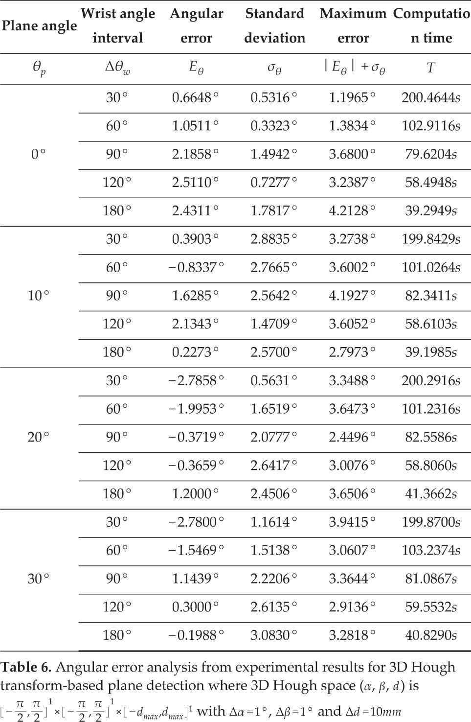
Similar to the experimental results about the PCA-based plane-detection method in Sec.4.2, the experimental results about both plane-detection methods based on RANSAC and the 3D Hough transform are shown in Table 5 and Table 6, respectively. In the case of RANSAC, both the average angular error Eθ and the standard deviation σθ for each angle interval Δθ w of the wrist increase monotonically as the plane angle θ p increases, similar to PCA. On the other hand, in the case of the 3D Hough transform, neither Eθ nor σθ for each Δθ w seem to be closely related to θ p . However, in both experimental results, the maximum error (| Eθ | + σθ) for each Δθ w increases monotonically as θ p increases, while (| Eθ | + σθ) for each θ p does not increase monotonically but tends to increase as Δθ w increases, similar to PCA. The comparison results for Δθ w = 30°, 180° are shown in Figs. 9(a) and 9(b). In the case of Δθ w = 30°, the maximum error for each method increases as the plane angle θ p increases, as shown in shown in Fig. 9(a). Thus, the accuracy of the plane parameters can be improved by iterative plane detection. In this case, the tolerable error ET and the mechanical error Em of the manipulator are set as 1.5° and 3°, like in Sec.4.2. First, the error of the 3D Hough transform is larger than those of the others regardless of θ p , and the reference angle θ ref with respect to ET is 1.47°. If the detected plane angle is greater than θ ref , the plane detection and the alignment motion should be conducted iteratively until the aligned plane angle is less than or equal to θ ref . However, the plane with an error of less than ET cannot be obtained successfully since the plane angle is greater than at least 4.47°, after the manipulator's alignment motion under the constraint of the mechanical error Em = 3°. On the other hand, the error of RANSAC is approximately equal to that of PCA. In this case, the reference angles θ ref of RANSAC and PCA are 5.98° and 7.21°, respectively. If the plane angle detected by RANSAC is greater than 5.98°, the alignment motion is needed for precise plane detection. In this case, just one alignment motion is sufficient for detecting the plane within the tolerable error ET, since the first aligned plane-angle is less than at least 5.6159° in the worst-case scenario for θ p = 30° under the constraint of Em = 3°. Nevertheless, PCA is more precise than RANSAC since the error of PCA is less than that of RANSAC in the vicinity of θ p = 0°. Next, in the case of Δθ w = 180°, the maximum error of each method is shown in Fig. 9(b). First, the error of the 3D Hough transform does not seem to be closely related to θ p because the results are increasingly affected by distance measurement noise as the number of detected points decreases. In addition, the error for all θ p is greater than ET, and it is not possible to detect the plane successfully. Although the error of RANSAC is less than that of the 3D Hough transform, the error for all θ p , is also greater than ET, and thus successful plane detection is not possible. Of course, in the case of PCA, successful plane detection is also very difficult, as described in Sec.4.2. However, by replacing the manipulator with a more accurate one, the probability of successful detection can be increased. On the other hand, in the case of the 3D Hough transform and RANSAC, successful detection is not possible under the constraint of ET = 1.5°, however small the mechanical error Em of the manipulator. From the computation time's point of view, the average computation times for the 3D Hough transform, RANSAC and PCA are 95.5318s, 0.4129s and 0.0570s, respectively. In this case, the 3D Hough transform is more than 230 times slower than RANSAC, and 1670 times slower than PCA. Thus, the 3D Hough transform is not appropriate for real-time robot control. RANSAC is much faster, but is itself more than seven times slower than PCA. Consequently, the PCA-based plane detection method is more appropriate for real-time welding robot application with respect to both accuracy and computation time. Of course, through additional post processing or appropriate parameter tuning the accuracy of the 3D Hough transform and RANSAC methods can be improved, but computation time for the additional processing increases, or it takes additional effort and time to find appropriate parameters.
Angular error analysis from experimental results for RANSAC-based plane detection with α=0.955, P=0.999 and N=4 where α, P and N are the ratio of inliers, the probability of successful detection and the number of iterations, respectively

Angular error analysis from experimental results for 3D Hough transform-based plane detection where 3D Hough space (α, β, d) is

Comparison results for PCA, RANSAC and 3D Hough transform-based plane detection methods
5. Conclusions
The hand-eye LRF-based precise plane-detection method was proposed for autonomous robotic welding in the field of shipbuilding. The robotic welding system consists of a 6 DOF manipulator with an LRF on its wrist. The plane is detected by PCA (principal component analysis) using the LRF data, which are obtained only by the rotational motion of the wrist in order to reduce the mechanical error caused by additional motion of the manipulator. In the simulations, the accuracy of the plane detection was analyzed with respect to the change of the plane angle, and the iterative plane detection method with the manipulator's alignment motions is proposed to reduce the plane angle close to zero, since the error increases as the plane angle increases. In addition, accuracy was analysed with respect to the change of the wrist's angle interval that determines the number of the wrist's rotations. As a result of the analysis, the number of the wrist's rotations could be reduced, taking the requirements for successful autonomous robotic welding into consideration. Besides this, the results of the analysis can be used to determine an acceptable specification for the manipulator. For verifying the feasibility and effectiveness of the proposed method, experiments were carried out with the prototype of the hand-eye LRF consisting of the 1 DOF wrist joint, the LRF sensor system and the rotatable plane. Although the error is relatively larger than that of the simulations, the tendency of the error with respect to the change of the wrist's angle interval and plane angle is similar to those of the simulations. Using the proposed method, the welding plane can be detected precisely for successful, autonomous robotic welding. Also, the analysis results of plane-detection experiments can be used to determine the specifications of the autonomous robotic welding-system in the field of shipbuilding. In addition, the experimental results for PCA were compared with those for the other representative plane-detection methods, based on RANSAC and the 3D Hough transform, where the parameters of the methods were appropriately defined for the LRF-based plane detection. According to the comparison results, PCA is remarkably better than the others regarding both accuracy and computation time. In other words, PCA is more appropriate than the others for the proposed iterative plane-detection method, using LRF data.
Footnotes
6. Acknowledgements
This work was supported by Brain Korea 21 PLUS Project and Basic Science Research Program (2013R1A1A2012578), through the National Research Foundation of Korea (NRF) funded by the Ministry of Education.