
Abstract
The objective of this paper is to develop a novel human-manipulator interface which incorporates wearable-based and markerless tracking to interact with the continuous movements of a human operator's hand. Unlike traditional approaches, which usually include contacting devices or physical markers to track the human-limb movements, this interface enables registration of natural movement through a wireless wearable watch and a leap motion sensor. Due to sensor error and tracking failure, the measurements are not made with sufficient accuracy. Two Kalman filters are employed to compensate the noisy and incomplete measurements in real time. Furthermore, due to perceptive limitations and abnormal state signals, the operator is unable to achieve high precision and efficiency in robot manipulation; an adaptive multispace transformation method (AMT) is therefore introduced, which serves as a secondary treatment. In addition, in order to allow two-way human-robot interaction, the proposed method provides a vibration feedback mechanism triggered by the wearable watch to call the operator's attention to robot collision incidents or moments where the operator's hand is in a transboundary state. This improves teleoperation.
Keywords
Introduction
Human beings cannot play any active role in complex, challenging or risky tasks in highly unstructured dynamic environments where objects are changing shape, but these tasks can often be achieved by robots. It is therefore important to establish an effective human-manipulator interface in such circumstances [1]. Existing human-manipulator interfaces are widely used, and can be roughly classified into three kinds: (1) contacting interface; (2) marker-based interface; (3) markerless interface.
Contacting interfaces [2] usually contain devices like joysticks, inertial sensors, or exoskeleton systems to track human-limb movements as a system input [3, 4]. Although this can fulfil the basic requirements of human-robot interaction, the devices used are not very natural or comfortable, and hinder human-limb movements in some cases.
The marker-based interfaces are non-contacting and thus seldom hinder natural human-limb movements. However, physical markers are rigidly attached to body parts to recognize movement [5]. When the operator's movements are occluded, especially in some dexterous tasks [6], marker-based interfaces are not always practical.
By contrast, markerless interfaces [7, 8] rely on taking pictures of the operator's movements or figuring out the operator's gestures to acquire disparities in the movements of the operator's limbs with the last recorded posture. Obviously, markerless interfaces seem a better option for robot manipulation: they are often less invasive and avoid problems of marker occlusion and identification [9]. Many studies on markerless interfaces have been proposed, but many limitations still exist [10, 11]. The method developed by Kofman et al. enabled the operator to control the robot naturally by tracking the movements of the operator's hand in a 3D space [12]. However, the method needs to satisfy many extreme operating conditions in the initialization state. For example, it requires the operator to operate manipulation on a dark background, with his/her hand higher than the shoulder. As it is also affected by too-bright or too-dark lighting conditions, a precise result is difficult to obtain with the method. Du et al. proposed a markerless human-robot interface which allows the operator to perform human-robot interaction through waving his/her hand within the operating space [13]. However, the method has many potential disadvantages and limitations based on the tracking system and filtering algorithms on which it relies. First of all, one leap motion sensor cannot produce enough redundant data to eliminate the tracking error, and there is no feedback mechanism when the robot is in a collision or the operator's hand is not in the operating space, that is, the method can only be used for one-way human-robot interaction. Besides, a particle filter employed in the method for posture estimation needs to resample and use particles to estimate the conditional mean and covariance matrix. Generally, it is difficult to meet the real-time application requirements. In addition, there is a synchronization correlation whereby position estimation depends on orientation estimation during the posture estimation period, which severely decreases the efficiency of the method.

Flowchart of the interface
Taking all the factors into consideration, this paper proposes an innovative human-manipulator interface which uses one wearable watch to capture the orientation of the operator's hand, and one leap motion to locate the position of the operator's hand simultaneously. The watch not only assists in solving the problem of edge precision, but also reports system states in the tracking process – robot collision situations, or situations where the operator's hand is in a transboundary state – through a vibration in the wearable watch to attract the operator's attention.
The communication module thus decreases failures and the tracking error of the robot manipulation. Nevertheless, the tracking system also has the following disadvantages:
The measurements obtained by the sensors have white noise and show nonlinearity.
Sometimes the tracking system is not accurate enough, especially when the operator's hand waves around the edge of the operating space.
The operator has to reset his/her hands because of the limited operating space, which brings about unstable and incoherent robot manipulation.
Dual Kalman filters are therefore employed to compensate the measured orientation and position of the operator's hand, respectively. This gets rid of the synchronization question in posture estimation, as Kalman filters work independently to estimate the operator's movements (Fig. 1). Furthermore, the inherent perceptive limitations of humans lead to the operator's incapacity to perform precise and efficient robot manipulation. A velocity control algorithm called adaptive multispace transformation is therefore also introduced. The processed data replace the measurements to drive the robot manipulator.
The remainder of this paper is organized into six sections. Section 2 illustrates the coordinate system and calibration in detail. In Section 3, the Kalman filters for orientation estimation and position estimation are developed. Section 4 describes the vibration feedback mechanism used in collision detection and transboundary detection. Section 5 focuses on the adaptive multispace transformation method for precision and efficiency adjustment. In Section 6, related experiments and results that validate the effectiveness of our interface are presented, followed by concluding remarks in Section 7.
Coordinate System
The wearable watch (Geak watch), based on the Android 4.1 system, consists of one three-axis magnetometer and one two-axis gyroscope to track the orientation of the operator's hand [14]. The orientation can be obtained by integrating the angular velocity and quaternion obtained from the magnetometer and gyroscopes, respectively. The leap motion, integrating gesture recognition technology, accesses the position data by integrating the acceleration information [15]. The 3D orientation and position of the centroid on the hand are transmitted to control the robot manipulator.
To define the movements of the operator's hand in 3D space, leap motion frame X L Y L Z L , world-fixed frame X W Y W Z W and hand frame X H Y H Z H are established, as shown in Fig. 2. Because the watch is rigidly attached to the operator's hand, the watch frame is assumed to coincide with the hand frame. The origin of the hand frame is the centroid on the hand. X H is collinear with the middle finger and points outward. Y H is perpendicular to the back of the hand and points upward. Z H is the multiplication cross of X H and Y H . The position of the operator's hand is defined by the translation between the leap motion frame and the hand frame in each axis, and the orientation uses the rotation angles in the yaw-pitch-roll frame. φ, θ and ψ denote the yaw, pitch, roll angles between the hand frame and the world-fixed frame in each axis, respectively.
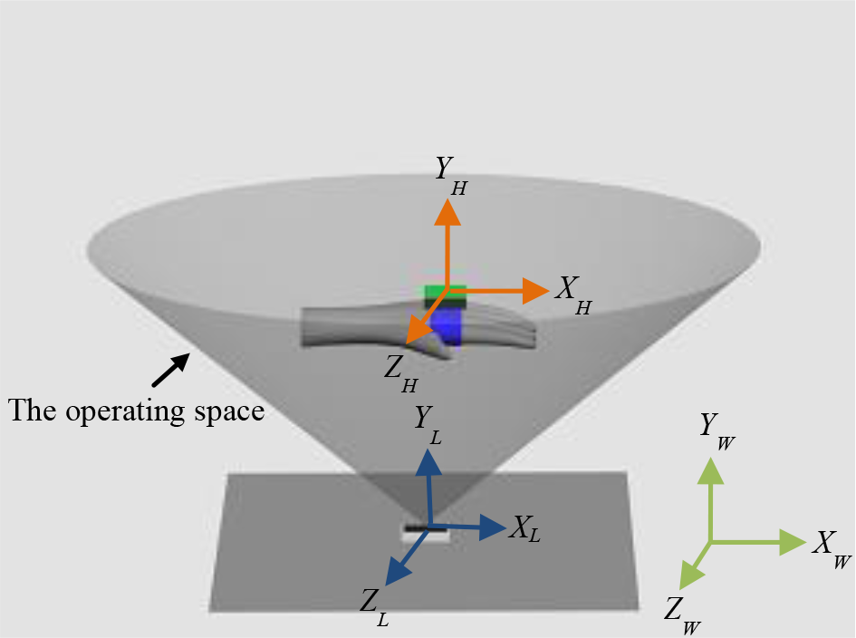
Coordinate system
Coordinate calibration is very necessary to synchronize the movements between the operator's hand and the robot manipulator. Suppose that a spatial point in the hand frame is [x h , y h , z h ], and this spatial point mapped to the world-fixed frame is [x w , y w , z w ]. Then, we have:

where T is the transformation from the hand frame to the world-fixed frame. For each transformation, six uncertain parameters can be determined, so three non-collinear points can determine this transformation. In order to find the more precise transformation, the Least Square Estimation (LSE) [15] is adopted using more than three non-collinear points.
The Kalman Filter
The Kalman filter presents an optimal solution of the nonlinear measurements by assuming that the posterior density is Gaussian. The simplicity, recursive structure, and mathematical rigour of the Kalman filter make it well-suited and attractive for nonlinear and Gaussian models. Through recursive update of its finite-dimensional statistics to accurately recover the real measurements, its stochastic model describes the stochastic properties of the system process noise and the observation error. Unlike other filters, such as the particle filter, the Kalman filter is at the basis of the iterative method and minimum variance principle, and completes all the procedures without any interruption. The Kalman filter is therefore more attractive for nonlinear measurements in orientation and position [17].
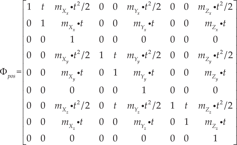
The Kalman filter model, composed of the system state model and a measurement model, is defined as follows:


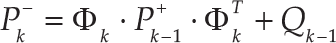
Suppose t k is the iteration time represented by the subscript k. Hence, x k and z k denote the state vector and the measurement vector at time k, respectively. uk−1 denotes the deterministic input vector, wk−1 stands for the process noise vector, and v k denotes the measurement noise vector. Φ k refers to the system transition matrix from time tk−1 to time t k . Γ k and H k are the input matrix and the measurement matrix, respectively. Expressing the state vector and the measurement vector in the forms of equation (2) and (3), the posterior density function with mean and covariance can be estimated by the Kalman filter. The Kalman filter is achieved by prediction and update processes [18].
Predicted state:

Prediction covariance matrix:
Kalman gain matrix:

Estimated covariance matrix:

Estimated state:

The factored quaternion algorithm is based on a set of measurements from the magnetometer and the accelerometer. It produces a quaternion output to represent the orientation without singularities. However, the factored quaternion algorithm is used for orientation estimation of a static or slow-moving target with respect to the world-fixed frame [19]; it is not applicable to a dynamic situation with relatively large linear accelerations, unless a complementary or optimal filter is adopted together with angular rate information.
According to Euler's theorem on finite rotations, the conversion from Euler angles to the quaternion is expressed as follows [20]:

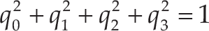
where φ is the roll angle around the X H axis, θ is the pitch angle around the Y H axis, and ψ is the yaw angle around the Z H axis. q0, q1, q2 and q3 are the quaternion components that should satisfy:
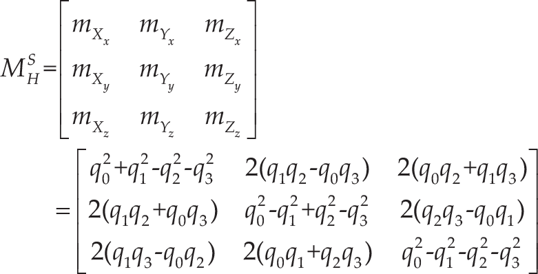
Because the quaternion can be obtained from the factored quaternion algorithm, the direction cosine matrix from the hand frame to the world-fixed frame is:
The differential equation of the quaternion q with respect to time t is written as:

where ω x , ω y , and ω z are the angular velocity states. Because the orientation state contains the quaternion states and the angular velocity, we define the orientation state as:

The quaternion components at time t k can be calculated from the angular velocity measurements and the quaternion components at time tk−1 by using:
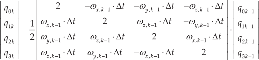
where Δt is the sampling time of the watch. Using equations (12) and (14), the state-transition matrix will result in:
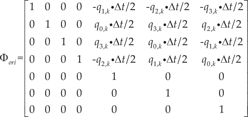
Γ ori is a zero matrix because the system has no control inputs. The quaternion states can be estimated by the angular velocity. Define the process noise vector as:
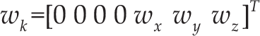
where w x , w y and w z are the process noise components of the angular velocity. Since the wearable watch is calibrated and initialized to measure the angular velocity, the observation matrix H ori for orientation estimation can be expressed as:

where n is the number of the angular velocity vector and p is the number of the quaternion. In this paper, n=3 and p=4. Because the orientation is calculated using a unit quaternion, the determined quaternion q k at time t k is normalized and written as:

Assume P(p x , p y , p z ) is the coordinate of the centre of the operator's hand in the world-fixed frame. Since the leap motion has access to the three velocity components, according to the direction cosine matrix from the hand frame to the world-fixed frame, the acceleration of the hand with respect to the world-fixed frame can be calculated by the following equation:
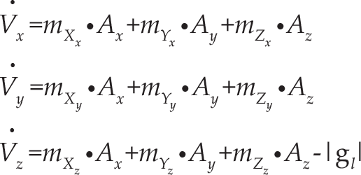
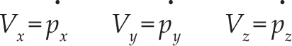
where |g l | is the magnitude of the local gravity vector, and A x , A y and A z are the acceleration measurement components in the hand frame. The velocity components V x , V y and V z in the world-fixed frame can be expressed as:
Define the position state at time t k as:

According to equations (19) and (20), the state-transition matrix φ pos will be obtained:
Since the system has no control input, the acceleration measurements are affected by gravitational force. The Z-axis is also parallel to the gravity vector. Hence, the system input matrix is achieved:

Then, the process noise vector can be written as:

where w x , w y and w z are the process noises of the acceleration in each axis.
Since the leap motion was calibrated and initialized to measure the acceleration of the operator's hand, the observation matrix for position estimation can be expressed as:

As a result, the estimated position of the operator's hand P k (p x,k , p y,k , p z,k ) is determined.
Collision Detection
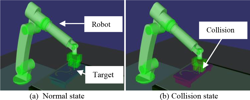
If a robot collides with a target, a vibration feedback will appear in the watch by socket communication. To determine the occurrence of collisions, the static K-DOPs collision detection technique [21] is used in our method. If any collision is detected, the sensors will not obtain the operator's movements; otherwise, the path between the starting point and the end point is quartered. Fig. 3(a) shows the system in normal state and Fig. 3(b) shows it in collision state. The collision detection algorithm is as follows.
Build a K-DOPs path bounding box and performing intersection detection of the bounding box.
Detect the bounding box whether there is an intersection or not. If yes, determine whether or not the interval is less than the given threshold and divide this interval into equal halves.
Perform recursive detection. The bounding boxes used in detection are path bounding boxes.
Performing dynamic intersection detection against the leaves bounding boxes. If intersection is found, a collision is detected and a vibration is triggered in the wearable watch.
Collision Detection
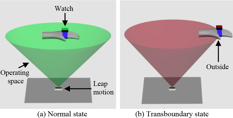
As shown in Fig. 4(a), transboundary detection is always performed to calculate whether the operator's hand is beyond the operating space or not. When the operator's hand is in the operating space, the measurements can be obtained by the sensors and then transmitted to the robot receiver to drive the robot manipulator. If a transboundary circumstance arises (Fig. 4(b)), the measurements will be neglected, and a vibration feedback in the watch reminds the operator to move his/her hand back.
Transboundary Detection
Due to inherent perceptive limitations related for example to time and distance, as well as physiological tremor, the operator cannot accomplish precise and efficient robot manipulation without assistance. To eliminate the negative influence of these sources and improve the accuracy and efficiency of robot manipulation, a modified version of adaptive multispace transformation is employed to establish a secondary treatment for the measured data [22].
As shown in Fig. 5, two scaling processes are introduced to relate the robot workspace to the operator workspace dynamically. The actions of the hand in the master space (MS) are related to the virtual unit vector of the central axis of the robot manipulator K in the visual space (VS), through scaling variable S; another scaling variable u is used for the robot movements and the virtual unit vector K. Both S and u are scalars whose values are a function of the distance r between the end-effector of the robot manipulator and the target in the robot workspace (WS) [23].

Representation of the human-interface-robot spaces
When the robot end-effector approaches a target, the virtual unit vector K is affected by S between MS and VS. When S > 1, it accelerates the motion of K. When S < 1, it decelerates the motion of K. The vector K is also affected by u between VS and WS. Since the robot velocity can be dynamically adjusted through such scaling modifications, it is clear that these processes have a direct effect on the accuracy and efficiency of robot manipulation. The task execution time is reduced and performance improved accordingly.
Since the scaling vector S influences the motion of the virtual orientation and position, let S = [S
ori
, S
pos
], where S
ori
scales the virtual orientation and S
pos
acts upon the virtual position. Assume that

where δ
ori
is the orientation threshold value. When

where δ
k
and δ
k
┴
are the threshold values, and
When S
k
=S
k
┴
, the velocity
S ori and S pos are the functions of the distance r, which results in:

where C1, C2 and C3 are constants. Since MS and VS are affected by u, the velocity

where P
W
is the position of the robot manipulator in WS, P
C
is the position of the zoom centre in VS, and

where C1 and C2 are constants. As the increment of C1 and C2, the precision standard of the robot manipulation increases while its efficiency decreases, and vice versa. In the initial stage, C1 and C2 can be set to 1, which denotes that the velocity and accuracy requirements are equal in each experiment.
Environment of Experiment
Three kinds of sophisticated experiment – peg-into-hole, trajectory tracking and screwing bolt – were carried out to evaluate the performance of this method in terms of accuracy and efficiency. In each experiment, the wireless watch was tightly fixed on the operator's hand and the leap motion took place in front of the operator to track the movements. When the operator waved his/her hand, the measurements were obtained; the robot was then able to copy the movements of the hand by means of the inverse kinematics solution [24]. However, considering that the robot workspace is larger than the operating space, a reset gesture was defined in our interface. This meant the leap motion would not track the movements of the operator's hand while it was making a fist, enabling the operator to move his/her hand back and reuse the method. When the operator's hand was not in the operating space, the wearable watch would vibrate to attract the operator's attention.
In experiment 1, 10 peg-into-hole teleoperations were conducted to evaluate our method by comparing the number of failures with operation time. The laboratory environment of the peg-into-hole experiment is shown in Fig. 6. A peg of 14 mm diameter was installed on the robot end-effector and a steel plate with 16 holes was fixed under it. In each test, the local site operator controlled the remote robot to insert the peg into the 16 holes (16 mm diameter). To effectively ensure the security and success rate of the robot teleoperation, a virtual simulation system of peg-into-hole tests was completed for the feedback mechanism. The measurements were not directly transmitted to the robot, but went through a two-step treatment. In the first step, the measurements were transmitted to the virtual robot. If any collision was detected, no more commands were sent to the real robot and the last operation was reset. Otherwise, the measurements were used to operate the remote robot manipulator.

The peg-into-hole experiment environment
In experiment 2, a trajectory-tracking simulation experiment was carried out according to our method and that presented in [13]. The experiment environment is shown in Fig. 7. A default reference trajectory of 190 mm radius was designed before each test. The operator needed to control the robot manipulator to move along the reference trajectory from left to right using his/her hand, and the tracking error established by comparing the reference and tracking trajectories and the operation time was used to compare our method with that in [13]. When the distance between the reference trajectory and the real-time trajectory exceeded a threshold value of 5 mm, our method triggered a vibration feedback to warn the operator.

The trajectory-tracking experiment environment
In experiment 3, the leap motion took place in the centre of a table, and the operator's hands – with two watches – were waved over the leap motion (Fig. 8(a)). A bolt with a diameter of 75 mm and a length of 83 mm was installed on the robot end-effector, and a nut with a diameter of 75.5 mm and a length of 91 mm was firmly attached to another robot end-effector (Fig. 8(b)). In the initial stage of the experiment, the distance between the two robot manipulators was 203.7 cm. Since the gap between the bolt and the nut was very narrow, 0.5 mm, the accuracy and efficiency of the method could be evaluated by whether or not the operator could screw the bolt into the nut and the length of operation time. The failures refer to the failures of the operator to screw the bolt into the nut. The operation time refers to the time needed to control the robot manipulator to move close to another manipulator, adjust the orientation and position, screw the bolt into the nut, and separate the dual robot manipulators. To improve the success rate of the experiment, one camera with vision-based technology [25] was attached to the robot end-effector to locate the central axis of the end-effector of another robot. If the distance or the angles between the central axes of two robots exceeded a certain value, meaning that the bolt could not be screwed into the nut, a vibration feedback would immediately attract the operator's attention.

The screwing-bolt experiment environment
In this paper, two GOOGOT GRB3016 robots were used to conduct the experiments to verify the method. The DH parameters of the robot are listed in Table 1: a represents the length of the common normal, α refers to the angle about the common normal from the old axis to the new axis, d stands for the offset along the previous to the common normal, and θ represents the angle about the previous normal.
The DH parameters of the robot

Table 2 lists the operation time and failures for 10 peg-into-hole tests according to our method and the method in [13]. In each test, the peg was inserted in 16 holes. Since our method introduces a feedback mechanism to improve the probability of successful teleoperation, the failures in our method were minimal, and the mean (0.7), was smaller than in the method in [13] (1.8). The mean error in our method was thus reduced by 1.1. The operation time ranged from 192 s to 221 s, with a mean of 205.1 s. In comparison with the method in [13], the mean operation time decreased by 25.2 s. Therefore, the efficiency and accuracy of our method was higher.
Comparison of the operation time and failures in our method and the method in [13]
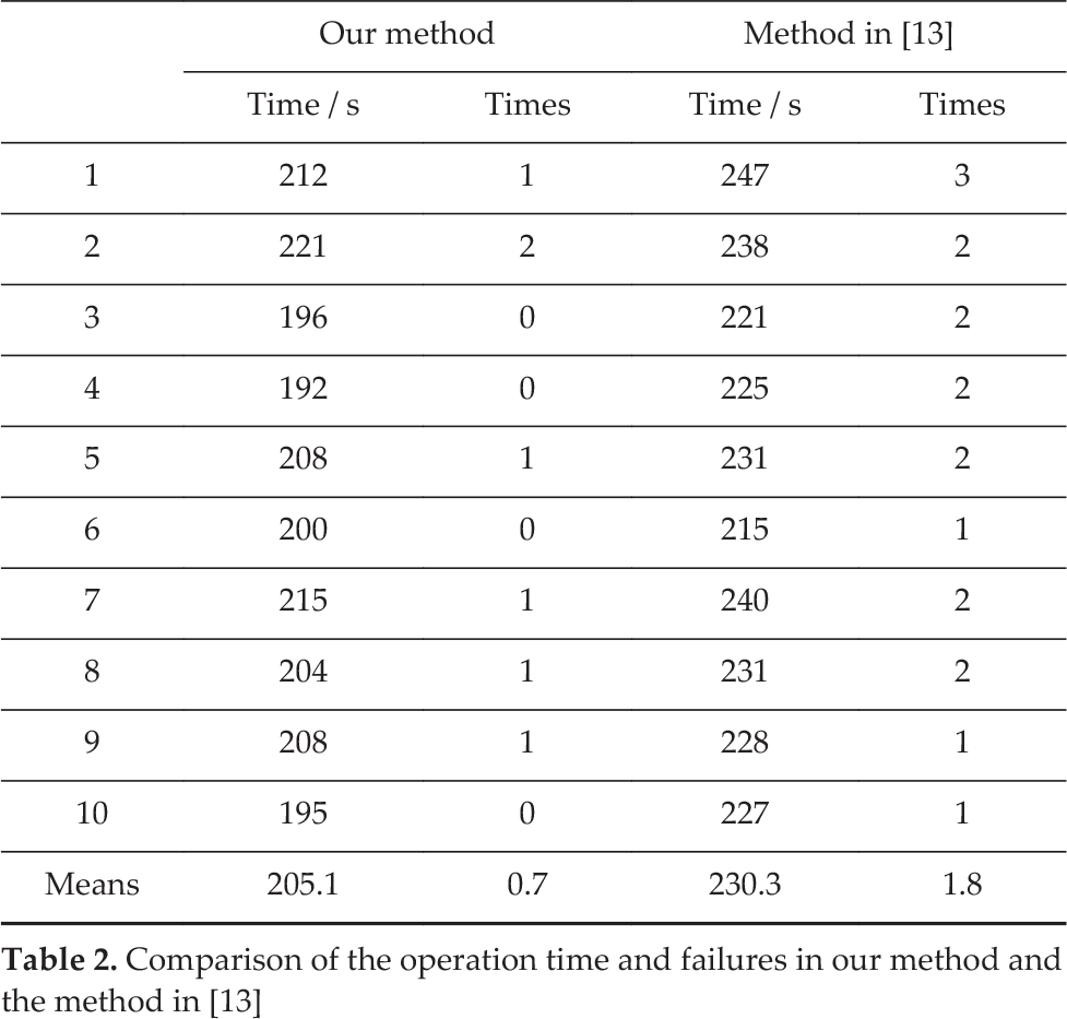
Comparison of the operation time and failures in our method and the method in [13]
Fig. 9 shows the trajectory-tracking paths in experiment 2. The red line shows the reference path, the blue dotted line is the tracking path of our method, and the light-blue dotted line denotes the tracking path of the method in [13]. Compared with the tracking path of the method in [13], the trajectory of our method seems closer to the reference path. Because our method added a feedback mechanism, the tracking failure is significantly reduced, as shown in Fig. 9. Table 3 makes a comparison of the tracking error and operation time of our method and the method in [13]. The mean error of our method, 1.82 mm, was smaller than that of the method in [13], which was 2.42 mm. Besides this, the mean operation time of our method was 215.8 s, while that of the method in [13] was 243.4 s. Fig. 10 shows the tracking error of our method and that of the method in [13] in the form of a histogram: the blue columns denote the tracking error of our method, while the red columns are the tracking error of the method in [13]. As the figure shows, the tracking error of our method is lower than that of the method in [13].

Tracking paths
Comparison of the operation time and tracking error

In experiment 3, the screwing-bolt was employed to compare our method with the method in [13] in terms of the operation times and failures. Table 4 shows the experimental results of 10 screwing-bolt tests. The operation time of our method ranged from 211 s to 233 s, with a mean time of 221.0 s. By contrast, the operation time of the method in [13] was longer, ranging from 228 s to 261 s, with a mean time of 243.9 s. Besides, the mean failures in our method was 0.9, compared to 1.6 for the method in [13]. Therefore, compared with the method in [13], the mean time decreases by about 21.9 s, and the mean failures decrease by 0.7.

Tracking error of our method and the method in [13]
Comparison of operation time and failures in our method and the method in [13]

In addition, experiments comparing our method with and without Kalman filters were conducted to show the contribution of the filters. Fig. 11 intuitively shows the measured and estimated results in experiment 3. Figs. 11(a) and (b) show the measurements and estimation in position, respectively. Figs. 11(c) and (d) are the measurements and estimation in orientation. The blue dotted line represents the measured results of the right robot and the red dotted line the estimated results of the left robot in the first 35 seconds. The blue crossed line refers to the estimated results of the left robot and the red crossed line to the estimated results of the right robot. Although the full task has a duration in the range of 211 s to 261 s, the results prove that the Kalman filter significantly improves the performance of the method, even if only the results for the first 35 seconds are shown.

Tracking results of posture measurements and estimations
This paper has presented a wearable-based and markerless human-manipulator interface that helps humans engage in natural and human-centred human-manipulator interaction. In the interface, one wearable watch and one leap motion are employed to register the continuous movements of the human operator's hand in real time; the inclusion of collision detection and transboundary detection achieve two-way feedback human-robot interaction and increase the probability of successful teleoperation. Moreover, methods using two Kalman filters and adaptive multispace transformation are developed to improve the performance of robot manipulation. By making full use of the proposed interface, an operator can perform robot manipulation with a sense of immersion, and collaboration with dual robots can be achieved flexibly even by a single operator [26].
The advantages of our method can be summarized as follows. Unlike contacting methods, our method does not interfere with natural human-limb movements. Furthermore, our method does not suffer from limitations related to marker occlusion and identification. It can be used immediately without any initialization [12], even if the operator is not a professional. In addition, unlike the method in [13], our method incorporates a wearable watch and two Kalman filters, leading to greater accuracy and better efficiency, since Kalman filters work independently to estimate the movements of the operator's hand. If the orientation is not very precise, the position estimation will not be affected. Furthermore, a vibration feedback can be triggered to report system states. Our method can be expected to find applications in areas human beings cannot access, such as deep sea and space.
However, as the operating space is very limited, a reset gesture has to be defined in this interface to reconduct robot manipulation. Further research towards multi-sensors and force control [27, 28] is underway to supplement the interface, enabling it to work more flexibly and advantageously.
Footnotes
8.
Project funded by “National Natural Science Foundation of China (Grant No:61403145)”, “Guangdong provincial science and technology project” (2014B090921007), “Guangzhou science and technology project” (20150810068), “Haizhuqu District Guangzhou science and technology project” (2014-cg-02).