
Abstract
Admittance controllers have been widely implemented in physical human/robot interaction (pHRI). The stability criteria and the parameter adaptation methods for admittance control have been well-studied. However, the established methods have mainly focused on human/manipulator interaction, and cannot be directly extended to mobile robot-based pHRI, in which the nonlinearity cannot be cancelled by feedback linearizations and the measurements of the relative human/robot position and orientation are usually lacking. In this paper, we study the pHRI between a human user and a mobile robot under admittance control. We develop a robotic system which can measure the relative chest/ankle positions of the human user with respect to the robot. Using the measured human position, a human frame admittance controller is proposed to remove the nonlinearity in the system dynamics. Based on the human-frame admittance control, a stability criterion is derived. By using a human arm stiffness estimator along with the derived stability criterion, a stiffness-based variable admittance controller is designed. The effectiveness of the proposed methods in improving the pHRI performance is tested and supported by simulations and experimental results.
1. Introduction
In the near future, robots are expected to cooperate with humans in the same shared workspaces in industrial and domestic applications. Therefore, pHRI is attracting increasing attention in robotics research [1]. Various types of robots have been created to physically interact with humans, including serial/parallel manipulators [2–8], mobile robots [9–11], biped robots [12], and aerial robots [13]. Among the robots created for pHRI, a mobile robot (platform) has its unique advantages in its large workspace, reliable stability during movement, and long battery life; mobile robots have been applied in applications including assembly assistance [14], walking support [15] and entertainment [16, 17].
To enable the robot to behave compliantly with the force/torque arising in pHRI, two control schemes—namely impedance control and admittance control [18]—have been introduced 1 . The impedance controller, which requires a specially designed back-drivable mechanical structure, is often used in haptic displays [20]. In contrast, the admittance controller fits the commonly-used manipulators and mobile robots that have high gear ratios [21], and it has been widely implemented in pHRI [4, 19, 22–33].
Theoretically, the coupled dynamics between a passive human and a robot under admittance control preserve such passivity as well as stability. However, in practice, the dynamics of other components (e.g., a low-pass filter as in [26]) or the time discretization [34] may give rise to instabilities. Therefore, the pHRI stability is often subject to the human arm's stiffness and the admittance parameters. To find appropriate admittance parameters that stabilize the pHRI for a given stiffness, the stability criteria for admittance controllers have been well-studied, especially in human/manipulator interaction [26, 27, 30, 33, 35].
Besides human/manipulator interaction, admittance controllers have also been applied in the physical interactions between humans and mobile robots [25, 32]. However, despite the success of their applications, the stability of human/mobile robot interactions has been investigated less frequently, and the established stability criteria for manipulators cannot be directly applied to mobile robots; for a manipulator, although its dynamics are usually nonlinear, when low-level control (e.g., using feedback linearizations) in the joint space is implemented, the translational motions of the end-effector have linear reponses to external forces [36]. However, the interactions between humans and mobile robots inevitably involve rotations that introduces nonlinearity. Consequently, the analysis of pHRI stability requires a non-trivial effort in formulating a Lyapunov function. Moreover, we will show that the techniques in formulating stability criteria for manipulators cannot be easily extended to mobile robots.
Besides stability, another issue in designing admittance controllers is pHRI performance. We could use very conservative admittance parameters (e.g., a very high virtual viscosity) to ensure pHRI stability under any uncertain stiffness; however, this high viscosity would also place an extra physical burden on the human user and it thus results in poor pHRI performance. To mitigate the trade-off between stability and performance, many researchers have proposed implementing a stiffness estimator in human/manipulator interaction and recommended adjusting the admittance parameters online according to the estimated human arm stiffness [19, 26, 27, 37]. Hereafter, we refer to this method as “stiffness-dependent variable admittance control” (SDVAC).
A stiffness estimator takes in two inputs: the force/torque in pHRI and the relative position between the human and the robot. In human/manipulator interaction, since the base of the manipulator is fixed and the human operator is often standing or sitting, the change of their relative position is simply the end-effector displacement, which can easily be obtained by the joint sensors and the forward kinematics. However, in the mobile robot case, as both the human and the robot are moving, their relative position and orientation are not equal to the displacement of the robot. Although in the previous literature laser rangefinders (LRFs) have been used to measure the human/robot distances for fall-prevention [32, 10], more detailed human information (i.e., the position and orientation of the human body) is still lacking. Consequently, the lack of human pose information restricts the application of SDVAC to mobile robots.
To overcome the two difficulties (i.e., formulating the stability criterion and estimating the human arm stiffness in the mobile robot-based pHRI), we developed a mobile robot which is able to measure the relative human position with respect to the robot using four on-board LRFs. Based on the developed robotic system, the following methods are proposed:
The robot is controlled so as to have admittance-type dynamics in the human frame. We show that the human frame admittance control can avoid the nonlinearity in the system dynamics and that the stability criterion can be formulated using linear system techniques.
With the human position information, the human arm stiffness can be estimated. Based on an improved stiffness estimator, SDVAC is implemented on the mobile robot.
With the above methods, we can stabilize the mobile robot-based pHRI and enhance its performance by adjusting the admittance parameters online. The proposed methods, as well as the developed robotic system, have the potential to be applied to human worker assistance, rehabilitation and robot dance partners [14–17].
This paper is organized as follows: Section 2 introduces the robotic system. The admittance control in the human-frame is discussed in Section 3. Section 4 formulates the stability criterion for the human-frame admittance control. Section 5 presents the improved stiffness estimator and the designed controller. Section 6 presents and discusses the results of simulations and experiments. Conclusions are presented in Section 8.
2. System Description
The developed robotic system (shown in Figure 1) is a test bed for a dance partner and walking support robots. This mobile robot has four omni-directional wheels, each actuated by a 250W DC servo motor. The maximum moving speed of the robot is 1.3m/s, which is approximately equal to the normal walking speed of a human. The control algorithm is implemented in real-time on an on-board PC with the QNX operating system.
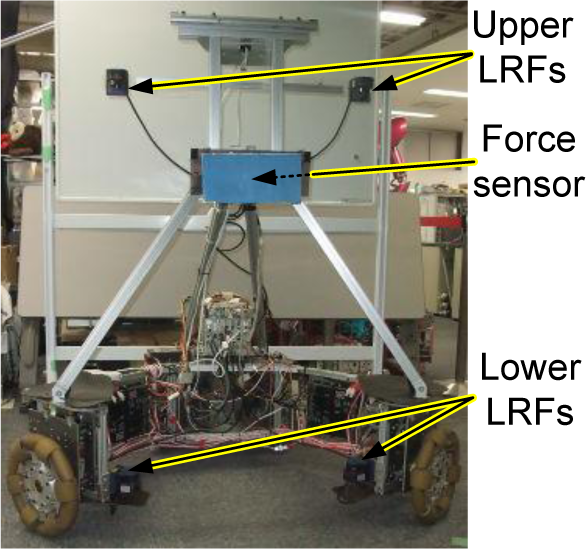
The developed robotic system—the force/torque sensor is installed in the waist of the robot (behind the blue plate)
Besides the encoders (installed on the motor shafts) and the force/torque sensor (installed in the waist of the robot) necessary for the admittance control, the mobile robot is also equipped with four LRFs (Hokuyo UBG-04LX-F01), with two upper and two lower LRFs monitoring the chest and each ankle of the human user respectively. In our earlier work, we implemented two LRFs to measure both the chest and the ankles (see Figure 2).
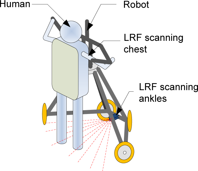
In our earlier work, the chest and ankle positions of the human were measured using individual LRFs
However, in the current robotic system shown in Figure 1, we use two pairs of LRFs to improve the quality of the measurements:
For measuring the chest, the paired LRFs have significantly greater coverage than a single LRF (see Figure 3).
in single LRF can measure both ankles when the human user is performing simple tasks (e.g., maintaining a static posture, as in Figure 2). However, when the tasks are complicated (e.g., when the human is rotating around the vertical axis or when the second through to the fifth sub-tasks in Figure 13 are being performed), the crossing of the ankles may occur (as shown in Figure 4), leading to occlusion problems (see Figure 5(a)). In this case, the positions of the ankles cannot be measured by a single LRF. Therefore, we implement a pair of LRFs to overcome this occlusion problem, as shown in Figure 5(b).

When measuring the chest of the human user, the paired LRFs (b) have significantly greater coverage than a single LRF (a)

Ankle occlusions may occur when performing relatively complicated tasks

When measuring the ankles of the human, the use of paired LRFs can eliminate occlusion, as illustrated in (a)
With the two pairs of LRFs, we can obtain range images of the chest and the ankles (shown in Figure 6). Using the range data, the positions of the chest and the ankles are calculated following the steps listed below:

A range image of the chest and the ankles. The black “+” and “x” markers denote the raw range data from the two lower LRFs. The red “+” and “x” markers stand for the range data from the two upper LRFs. Both “o” and “□” mark the calculated positions of the ankles and the chest respectively.
The chest and the ankles appearing in the range image are considered as an ellipse and two circles, respectively. At the beginning of each pHRI, the human user is required to stand near the robot for a few seconds, until the geometric parameters (i.e., the lengths of the major and minor axes of the ellipse, and the radius of the circles) are extracted.
Given a specific range image obtained during the pHRI, we first remove the spurious range image data that are significantly detached from the chest/ankle patterns.
Using the ellipse and circle parameters obtained in Step 1, the chest centre and its orientation are calculated by ellipse fitting while the ankle centres are obtained by circle fittings.
The calculated chest/ankle positions in a range image are shown in Figure 6. Using the calculated human-chest position, a stiffness estimator is introduced (Figure 7). The estimated stiffness is used to adjust the parameters of the admittance controller, whose output (the desired robot trajectory) is tracked by a low-level PD controller. The block diagram of the SDVAC-based system is given in Figure 7.
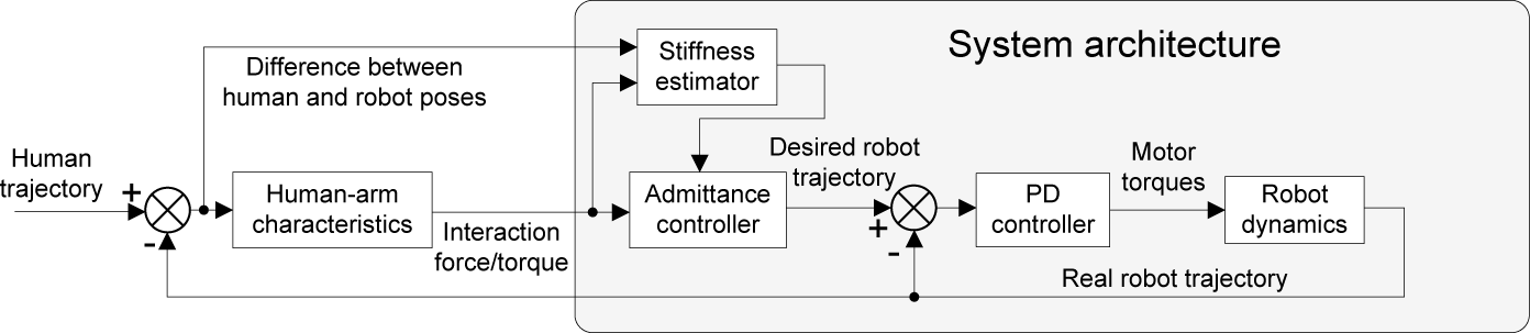
Block diagram of the proposed system based on SDVAC
Besides estimating stiffness, the measured human position is also utilized to determine the human coordinate frame in which we can define the admittance-type dynamics of the mobile robot. In the next section, we discuss the implementation of admittance controllers in different coordinate frames.
3. Admittance Control in Different Coordinate Frames
An admittance controller needs to be defined in a coordinate frame. In our application, where a human user physically interacts with a mobile robot on the ground, it is natural to consider three candidate frames: the global frame Σ g (fixed to the ground), the robot frame Σ r and the human frame Σ h . Figure 8 shows a top-view of the three frames. For ease of modelling and without loss of generality, the origin of the human frame is defined as a point in front of the human user so that the robot is at the desired pose when Σ r and Σ h are aligned.

Top-view showing the ground, the robot and the human frames
Both the human and the robot are assumed to have three degrees of freedom (DOF). These are two-DOF translational motion along the horizontal ground and one-DOF rotation around the vertical axis. For convenience, we name them as the x / y -dimensions and the θ -dimension, respectively.
The admittance control law of the robot is given by
where
The admittance-type dynamics defined in (1) do not correspond to any coordinate frame. In the next subsection, we show how different selections of coordinate frames can lead to different admittance-type dynamics in pHRI.
3.1 Admittance Control in the Global Frame
The admittance control law in the global frame is

where
If the human and the robot are separated, (2) is a simple linear system. However, nonlinearity arises when the human and the robot are physically coupled via the human's arms. For simplicity, we approximate this arm connection with a stiffness matrix and ignore the effect of viscosity 2 . With the stiffness matrix, the interaction force is modelled by

where
The human pose is transformed to the global frame by

where
Similarly, the transformation from

From (2), (3), (4) and (5), the system dynamics in the global frame are

where
Due to the nonlinearity, the stability of (6) cannot be examined by the Routh–Hurwitz criterion (as in [35]). Instead, a Lyapunov function (as in [38]) is formulated as a sufficient condition for stability. Here, we introduce a Lyapunov function using the mechanical energy of the human/robot system:

We directly give the result of V̇ = dV / dt. Assuming an autonomous system with the input

where
However, although the global-frame admittance control is stable, it exposes two problems in (6), (7), (8) and (2):
The first problem is nonlinearity, which is introduced by transforming
The second problem lies in (2), where
3.2 Admittance Control in the the Robot Frame
The admittance control in the robot frame is
where
By taking the time-derivative of (4), and using the facts that

where
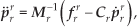
From (9), (10) and (3), the system dynamics are given by
Compared with the global frame admittance control in (6), the robot frame admittance control in (11) does not have the orientation-dependency problem. In addition, (11) contains only one nonlinear component (θ r r ) and looks simpler than (6). However, formulating a Lyapunov function for (11) is actually much more challenging (e.g., the dissipative-energy condition used in (8) is not preserved here). The authors are still trying to formulate a Lyapunov function for (11). Moreover, we might also expect that, if extra filter/controller dynamics are introduced, the stability analysis will become even more non-trivial.
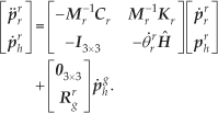
3.3 Admittance Control in the Human Frame
The admittance control in the human frame is
The force/torque defined in the human frame is

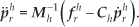
With (12) and (13), the system dynamics in the human frame are

Since (14) is linear, its stability can be tested with the Routh–Hurwitz criterion. Instead of directly checking the

where λ is the eigenvalue of the state matrix and det(·) denotes the determinant of a given matrix.
Besides the Routh–Hurwitz test, we can also use a similar Lyapunov function as in (7). By assuming that
Besides the linear dynamics, another use of the human frame admittance control is to decouple the three-DOF robot dynamics in the human frame. If we select the virtual mass
4. Stability of the Human Frame Admittance Control
The dynamics in the three dimensions can be decoupled; therefore, without loss of generality, we consider the robot dynamics in the x -dimension,

where kx, mx and cx are the first diagonal entries in
However, although the admittance controller itself is stable, when it is combined with other components, instabilities may arise. For example, Duchaine studied the effect of a low-pass-filter [26] in a haptic device with slight inertia and friction. In contrast, our system is a human-size mobile robot which has significant inertia and is subject to significant ground friction. Therefore, a PD controller is used for reference trajectory tracking. Besides the PD controller, another factor in our system is the relatively long sampling period (28ms) of the LRF used for sensing the human. This discretization also influences stability. Therefore, in this section, we study the stability criterion which takes the discretization and the PD controller into account.
At moment k, let the robot state be

where ts is the sampling period. With the current state

where kP, kD and kA are controller gains. Due to the discretization, the actuation force τ x is held (by the ZOH, i.e., zero-order hold) until moment k + 1 and the robot is driven to a new state x(k + 1). We approximate the mechanical admittance of the robot with a first-order system:

where mR and dR are the physical mass and viscosity, respectively. The discretized system dynamics are
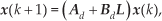
where
System (20) is stable if the two eigenvalues of
5. Stiffness-based Variable Admittance Control
5.1 Stiffness Estimation
In the previous section, we showed that, to guarantee the stability of pHRI, the admittance parameters should satisfy a stiffness-dependent inequality. Therefore, identifying arm stiffness is the prerequisite for variable admittance control [19].
In previous investigations, arm stiffness has been estimated by performing a linear regression on a fixed number of samples of the force/position measurements [19]. However, if the human arm stiffness rapidly changes (which frequently occurs in pHRI), fitting the fixed-size samples may temporarily generate poor results. An example is given in Figure 9. Assume that the number of force/position samples used in the linear regression is 20. At moment k, the samples are xk-19, xk-18,… and xk. We also assume that the arm stiffness rapidly increases between the sampling moments of xk-5 and xk-4. The 20 samples are shown in Figure 9(a). Because of the rapid stiffness change, the 20 samples diverge into two groups. Consequently, performing a linear regression on all 20 samples leads to an incorrect fitting result, which is shown in Figure 9(a).

When the stiffness changes rapidly, the proposed method gives a better fitting result. In (a), the “+” markers denote the sampled data. Segments with the circular and crossed markers show the fitting results of the original method and the proposed method respectively. In (b), the thin, plain curve is the true stiffness. The “+” markers and the thick curves show the original method and the proposed method respectively.
The poor fitting result, which is caused by rapid stiffness changes, can be solved by using samples of a variable size: Instead of fitting a fixed number of samples, we can perform linear regressions on multiple possible sample sizes until the optimal fit is found. To determine which fitting result is optimal, we can use the correlation coefficients as the index of optimality. The proposed estimation method is given in Algorithm 1. Results from the original and the proposed stiffness-estimation methods are compared in Figure 9(b). According to the comparison, we can see that the proposed method performs better under a rapid stiffness change.
The proposed stiffness estimation method

5.2 The Stiffness-based Variable Admittance Control
Theoretically, both the virtual mass mx and the virtual viscosity cx can be varied in SDVAC. However, in practice, the virtual mass mx is usually restricted by other factors. For example, in our system, the force sensor is installed in the waist of the robot and there is an upper-body structure above the force sensor (see Figure 1). Due to the inertia of the upper body, mx cannot be arbitrarily small. Otherwise, the small mx may lead to large robot accelerations and the upper body will conversely apply significant inertial forces on the force sensor, introducing noise or even instabilities. Because of this constraint, in this paper, we keep the virtual mass constant and only vary the virtual viscosity.
The system parameters are listed in Table 1, with the sampling period t s = 28ms. The relationships between the virtual mass and viscosity are shown in Figure 10.
The parameters used in the SDVAC design and simulations. mR and dR were identified in a preliminary test using the step response of the robot to motor torque inputs.


Contours of the pHRI stability with respect to human arm stiffness and virtual viscosity. The contour values greater than 1 indicate instability.
The values in the contour denote max || λ ||2 of the matrix
Therefore, we choose the following linear rules for SDVAC:

which is to be experimentally tested in Section 6.2.
5.3 Compensating for the Human's Future Trajectories
Besides SDVAC, the pHRI performance may also be improved by estimating and compensating for the human's future trajectories. The existing methods for future trajectory estimation in [27, 30, 32] cannot be directly applied to our application, where the human user walks with the robot and frequently varies his/her direction of motion. Consequently, the force information is often a result of body dynamics rather than a sign of human intention. Therefore, in the following, we propose and test a new heuristic method.
Empirically, a human's future trajectory is correlated with his/her feet positions and velocities. Let
The swinging foot has a non-zero velocity q̇gs, and
qgL - qgs and q̇gs form an acute angle.
The above rules give

where fgv is the virtual compensation force in the global frame. a1 and a2 are the user-specified gains (determined in preliminary trials according to the human user's subjective evaluations of the compensation intensity). h (·) is the unit step (or Heaviside) function, and β is defined as

where ɛ >0 is a small value used for avoiding singularity. fgv will later be added as a virtual compensation force to the input of the admittance controller. Note that the proposed compensation method does not work in the θ -dimension, as the human's feet trajectory can hardly be used for predicting future rotations.
6. Simulations and Experiments
6.1 Simulations
In the first simulation, we assumed the human user is static with pgh =[0.1,0.2,0.3] T . The stiffness matrix was Kh =diag(4500,4500,1800). The responses of the robot using three admittance controllers were simulated with the parameters listed in Table 1 and the sampling period ts =28ms. Controller 1 had constant Ch =diag(70,70,30), Controller 2 had constant Ch =diag(10,10,5), and Controller 3 was SDVAC as in (21). The simulation results in the θ -dimension are given in Figure 11.

Responses of the robot in the θ -dimension. The thin curve is the response of Controller 2 and the thick curves (overlapped) are the responses of Controllers 1 and 3.
As predicted by Figure 10(b), Controller 2 exhibited marginally stable behaviour. In contrast, Controller 3 (SDVAC) exhibited similar stable behaviour to Controller 1. Therefore, the use of SDVAC in stabilizing pHRI is supported and Controller 2 cannot be used under significant human arm stiffness.
In the second simulation, the orientation of the human was set to follow a sinusoidal trajectory with a period of 5s and an amplitude of π/2 (Figure 12(a)). The stiffness of the human arm was assumed to vary randomly between 0 −1800N m /rad, and the standard deviation of the random changes was 100N m /rad. Note that this random-walk stiffness was only used to qualitatively demonstrate the resultant pHRI of the admittance control (which is to be experimentally tested in the next subsection). The simulation results in the θ -dimension are shown in Figure 12.

Simulation results in the θ -dimension. In (a), the black curve represents the human trajectory, the blue curve with “+” markers denotes the robot trajectory using Controller 1, and the red curve with “o” markers denotes the robot trajectory using Controller 3. In (b), the blue curve with “+” markers is the interaction torque corresponding to Controller 1 while the red curve with “o” markers corresponds to controller 3.
We can see that the pHRI is stable and that the torque has been significantly reduced, suggesting the enhancement of pHRI performance by using SDVAC.
6.2 Experiments
In the experiments, we evaluated the pHRI performances of the following controllers:
A constant admittance controller (CAC) with Ch =diag(70,70,30);
SDVAC with Ch varying according to (21);
(SDVAC-C) SDVAC with the compensation method given in (22).
The pHRI experiments were performed in an indoor environment with no obstacles in the experiment space. The robot used in the experiments was introduced in Section 2. To evaluate the performances of the three controllers, we designed a pHRI task containing the following steps:
Three markers were attached to the floor (see Figure 13). In Step 1, the human moves from the start marker to the end marker;
Turning 90° in the clockwise direction;
Moving rightwards (seen from the human user) to the middle marker;
Moving leftwards to the end marker;
Turning 90° in the counter-clockwise direction;
Moving backwards to the start marker.
The above procedure is illustrated in Figure 13. A skilled user (who knew the operation of the mobile robot) and a novice user participated in the experiments. In the beginning, several preliminary trials were conducted to familiarize the novice user with the experimental procedure and the robot. For each user, the pHRI task was performed for three trials to compare the performance of CAC, SDVAC and SDVAC-C.
The experiment results are shown in Figure 14. Comparing these results in Table 2, we can observe that the force/torque interaction in the SDVAC and SDVAC-C trials are significantly smaller than the force/torque in the CAC trials. For example, in the θ -dimension, the maximum torque has been reduced by more than 50% for both the skilled and the novice users. The significant force/torque reductions are also observed in the x and y dimensions. Since SDVAC and SDVAC-C demand less human effort in pHRI, their task completion times are also shorter: compared with CAC, both SDVAC and SDVAC-C correspond to over 32% and 42% time reductions for the skilled and the novice users, respectively. Moreover, performances of the novice user are similar to the skilled user in the SDVAC and SDVAC-C trials, possibly because the simplicity of the admittance control demands little training on the human's part.
Comparison of the experimental results using the three listed controllers. The values inside and outside the parentheses denote the results of both the novice user and the skilled user, respectively.


Procedure for the designed pHRI task—the three round dots at the bottom of each subfigure denote the start, middle and end markers attached to the floor. At each step, the human user is required to align the robot with a certain floor marker.

The results of pHRI performances using CAC, SDVAC and SDVAC-C. The thin black curves with the “+” markers denote the results of CAC. The thicker red curves stand for the results of SDVAC-C. The thickest blue curves correspond to the results of SDVAC.
We can also observe that SDVAC-C did not outperform SDVAC. Due to the complexity of human body dynamics during walking as well as the heuristic nature of SDVAC-C in (22), it is a challenging task to quantitatively understand this phenomenon. However, empirically, the human users reported that SDVAC-C was “too active” and prone to “overshoot”. An example of overshoot is the peak on the red curve at about 16s in Figure 14(e). This overshoot happened when the human user was making the transition from moving backwards to completely stopping (corresponding to the termination of step 6 in Figure 13). According to Figure 14(e), we can see that for CAC and SDVAC, the user spent roughly 5N in order to decelerate the robot. In contrast, for SDVAC-C, to cancel the effect of ankle velocity compensation and realize the robot deceleration, it took the human user approximately 20N, which causes significant degeneration in pHRI performance. Consequently, as the human users had to resist any overshoots, the advantages gained from the compensations were cancelled.
According to the experimental results, and compared with CAC, the proposed SDVAC method significantly reduced the interaction force and task completion time in the mobile robot-based pHRI. Moreover, the performance of SDVAC-C is similar to SDVAC.
7. Discussion
7.1 Practicability of Robot Frame Admittance Control
In practice, the robot frame admittance control implemented in the physical interaction between a human and a mobile robot demonstrates stable behaviours. However, due to its nonlinear dynamics in (11), its resultant pHRI stability is difficult to prove or disprove 5 . This implies that designing a variable-admittance rule for such a nonlinear system is of significant difficulty. Therefore, despite its practical stability, the robot frame admittance controller is not analysed or tested in the simulations or experiments.
7.2 Possible Improvements on the Experiments
The experiments discussed in Section 6.2 involved two subjects, and the use of SDVAC would receive stronger support if more subjects could be invited. At the same time, the fact that a low viscosity corresponds to a slight interaction force has been well-supported and applied in existing literature [19, 25, 27, 30–33, 37]. The viscosity of CAC is conservatively designed for the worst-case stiffness, whereas the viscosity of SDVAC is always smaller than or equal to (in the worst case) the viscosity of CAC. Therefore, the interaction force corresponding to SDVAC will be smaller than that of CAC. Figure 15 shows the viscosities of CAC and SDVAC. We can observe that the SDVAC viscosity is much smaller than the CAC viscosity for most of the experiment. Consequently, compared with the pHRI using CAC, the interaction force corresponding to SDVAC is significantly reduced. This observation matches the pHRI result of implementing SDVAC in human/manipulator interaction in [27, 37].

The viscosity parameters corresponding to the pHRI in 14(b). The dashed and solid curves denote the viscosities of CAC and SDVAC, respectively.
7.3 The Implementation of LRFs in pHRI
The reason for implementing LRFs instead of other sensors is the short distance (0.06m–0.6m) between the human and the robot. This short distance prevents the implementation of more commonly-used sensors (e.g., Kinect) in the pHRI. Moreover, as has been discussed in Section 2, in order to enlarge the coverage of human chest measurement and to prevent ankle occlusions (which frequently occur during complicated tasks), we implement four LRFs in total. In contrast, we performed tests using only two LRFs for detecting the upper body and the ankles in our earlier work [40, 41]; however, it turned out that the detection was only successful for simpler tasks, e.g., when the human/robot motions were limited in the sagittal plane [40, 41].
Because LRFs are expensive (each LRF costs approximately 1700 USD), the four LRFs implemented in the robot significantly elevate the cost and prevent the application of the proposed system outside laboratories. However, we can expect that new sensors—which can work at close range and which can be made inexpensive—may solve this problem. The focus of this paper is on the analysis and design of variable admittance controllers. However, in the near future, we will substitute the LRFs with new, inexpensive and close-range sensors.
8. Conclusions
In this paper, we studied the pHRI between a human user and a mobile robot. We developed a robotic system which can measure a human's chest/ankle positions using four LRFs. The pHRI dynamics using admittance controllers in the global, robot and human frames were analysed and compared. With the LRF measurements, we could implement human frame admittance control to remove the nonlinearity in the system dynamics, and derive a stability criterion considering the effects of the PD controller and time discretization. By using an improved stiffness estimation method along with the derived stability criterion, a stiffness-based variable admittance controller was designed. The proposed method for improving the pHRI performance is supported by simulations and experimental results.
The present work can be improved in several ways. First, the Lyapunov function corresponding to the admittance control in the robot frame is to be found. Besides, the current ankle velocity compensation method (SDVAC-C) was based on heuristics. To improve this method, a quantitative analysis and further comparison experiments with existing methods [27, 30, 32] are needed. Moreover, the current assumption as to the diagonal stiffness matrix and the estimation method can be improved by the methods in [27]. Finally, although the reduction of the interaction force using variable admittance control has been well-supported by the existing literature, more subjects should be invited in the experiments to test the potential instability in more complicated tasks (e.g., in pHRI closer approximating dancing with additional DOFs in the human's shoulders and pelvis). We will develop a new prototype to experimentally evaluate the performance of SDVAC in such complicated pHRI tasks [42].
Footnotes
1
In some of the literature [19], admittance control may also be referred to as “impedance control”. However, in this paper we follow the naming conventions of “admittance” and “impedance” made in [![]() ].
].
2
3
One possible solution to this problem is to adjust
4
In the diagonal matrix approximation of
![]() ], while the consequence of the diagonal matrix approximation on the pHRI stability is to be examined in experiments.
], while the consequence of the diagonal matrix approximation on the pHRI stability is to be examined in experiments.
5
We can observe that the right-hand side of (11) is an odd-ordered polynomial, which has a similar form to that of the example system discussed in [![]() ]. The Lyapunov function for such a system might be non-polynomial and it demands non-trivial effort.
]. The Lyapunov function for such a system might be non-polynomial and it demands non-trivial effort.