
Abstract
In order to clean the surfaces of air ducts in underground facilities, recent research has been conducted on driving the control and development of an autonomous mobile duct-cleaning platform. The duct-cleaning robots removes contaminants that are inside a duct using the friction between a rotating cleaning brush and the duct surface. For the effective removal of the contaminants and stable steering control of the autonomous mobile platform, the interaction force between the brush and the duct surface needs to be measured. However, it is not possible to achieve an accurate measurement of the contact force for the duct surface and brush, which has a nonlinear deformation characteristic. Therefore, in this study, a simple and robust controller has been proposed. This controller integrates the backstepping method with an I-PD controller for the robust platform control against irregular external forces on the cleaning brush. In addition, various trajectory tracking simulations have been conducted and the results present stable trajectory tracking of the mobile platform in air duct cleaning.
Introduction
Ventilation in underground facilities, like subway stations, and modern buildings is carried out using air conditioning equipment and air ducts. However, without regular cleaning of the ducts, contaminants composed of fine dust and particular matters are accumulated on the inner surface of the HVAC ducts. As a result, indoor air, which is provided through the HVAC, can also be contaminated. Therefore, various dust removal techniques to remove such contaminants from inside the ducts have been applied such as chemical sterilization, the compressed air method and mechanical brushing. It has been reported that the most efficient method for removing contaminates that adhere to the duct surface using a rotating brush is the mechanical brushing method [1]. In addition, autonomous duct-cleaning technology has recently been suggested. This involves attaching the brush with a robotic arm to a mobile platform [2]. The development of an autonomous duct-cleaning robot requires a steering control to run in the limited space inside the duct. It also requires friction force control between the rotating brush and the duct surface, as well as torque control of the mobile platform, with disturbances generated by the mechanical brushing. In particular, for contact force control on the duct surface, it is difficult to predict or measure the friction because it varies with environmental conditions, i.e., temperature, humidity, and the type of contaminants. Furthermore, the pressing force, which is exerted by mechanical brushing, becomes the disturbance that acts on the wheels of the mobile platform. This can prevent it from following the reference route. Thus, a robust trajectory tracking controller under dynamic uncertainties and various disturbances needs to be applied.
The driving control of a duct-cleaning mobile platform is similar to studies about the trajectory tracking of mobile robots. Moreover, the skid-steering system is applied to simplify the structure without a conventional steering mechanism. This changes the direction of velocity difference between the left and right wheels. The skid-steering system has been modelled with a nonholonomic constraint. It considers studies on the linearization of a nonlinear platform model to control trajectory tracking. As part of the research, a control algorithm that considers the actuator dynamics without estimating the velocity has been proposed in order to remove uncertainty of the wheeled mobile robot [3]. Additionally, to enhance the tracking performance, a dual adaptive neural network algorithm has been implemented to overcome the difficulty in establishing a dynamic model [4]. Meanwhile, various methods for trajectory tracking control by estimating the contact force between the tracked wheel and the path surface have been studied [5, 6]. An integrated model with kinematic and dynamic characteristics of a mobile platform has also been proposed in [7]. In addition, the controller has to provide a pivot turning functionality in the skid control. Trajectory tracking control using “perfect velocity” can be performed by applying a velocity command for a platform that is completely dynamic-modelled, while ignoring disturbances [8]. Implementing this “perfect velocity tracking” allows the mobile platform tracking to be on the reference trajectory, as well as stabilizing the tracking point error. However, for cases when disturbances cannot be ignored, reference trajectory tracking is possible. With this, the position error of the platform is asymptotically stabilized through the trajectory tracking control of the platform, which is equipped with a steering mechanism. A backstepping technique is used to provide feedback for the current velocity of the platform in order to determine the velocity commands [9, 10]. Furthermore, the friction force that is caused by contact between the rotating brush and the duct surface is difficult to calculate analytically or to estimate, like the friction coefficient between the trajectory surface and the wheels during driving. This makes it impossible to carry out accurate dynamic modelling of the platform.
As the platform position error in the lateral direction is reduced, the cleaning pressure of the rotating brush can be applied without loss. This aids the removal rate of contaminants [2]. In addition, introducing a fully unattainable parameter can reduce the trajectory tracking error such as a friction efficient that uses an additional neural network controller. That is, when it is difficult to obtain an accurate measurement and estimation of the state of the system, a local solution can be obtained by employing fuzzy logic.
However, the implementation of the training process of a neural network and the solution searching process of fuzzy logic requires a high processor capability and computational time [11]. Thus, to reduce the high requirement in practical implementation, various control techniques have been developed and integrated with the adaptive control method [12,13]. In this paper, a simple and robust control method is proposed to make possible the stable trajectory tracking of an autonomous duct-cleaning platform under uncertain disturbances. We also predict the interaction force between the rotating brush and the platform.
This paper is composed in the following order. Section 2 details the duct-cleaning robot design specifications and characteristics of the platform model. Section 3 provides kinematic and dynamic models of the mobile platform with applied nonholonomic constraint, as well as of the interaction force between the rotating brush arm and the platform. Section 4 presents the backstepping method with stability proved for closed-loop control systems and a trajectory tracking controller that combines an I-PD controller to minimize the platform tracking point error. Section 5 validates the effect of the trajectory tracking results of the platform with an application, through various simulations, of the controller.
Design of the Duct-cleaning Robot
A robot for cleaning air ducts that are used in underground facilities has been designed, as depicted in Figure 1. This duct-cleaning robot is composed of a platform body, a front brush arm and an upper brush arm. Its structure enables the effective cleaning movement for four surfaces of a rectangular duct in limited spaces. Two traction motors are independently installed on each of the two rear wheels of the mobile platform. The front and rear wheels of both sides are connected with a belt and pulley module. With this, steering is controlled by the velocity difference between the left and right wheels, without a conventional steering mechanism. A four-bar linkage mechanism is used in the front brush arm to clean the bottom surface of the duct. The reciprocating motion of the linkage mechanism can clean the bottom of the duct surface. The five-bar linkage that is installed on the upper brush arm has been designed to clean the side and upper surfaces of the duct. The workspace of the upper brush arm has been designed to cover a rectangular duct of the dimensions: W(mm)xH(mm) = 300×350 ∼ 500×500. These dimensions are frequently used in subway stations. The overall weight of 9.5kg, two 20W motors for traction, six motors for rotating and controlling trajectories of brush arms have been used.
The robot can be driven manually by a remote controller or driven automatically. Fn manual control mode, an operator can monitor the duct inside and the cleaning process can be monitored through a CCD camera, which is installed on the mobile platform. Fn automatic driving mode, the embedded controller in the platform manages the trajectory and speed, assigns the torque of each wheel and maintains a distance from the sides of the duct. The distance can be measured by an ultrasonic sensor, which is installed on both sides of the platform. The shorter the distance from the side of the duct, the more pressurizing force can be exerted to the brush during the sweeping of the surface of the ducts.
Since the pressure to the rotating brush from the duct surface affects the driving direction of the platform, the implemented controller has to contain torque control of the traction motor against disturbances and repulsive force from the duct surface. Additionally, the controller requires stable trajectory tracking of the platform inside the duct. Figure 1 depicts a prototype and the dimensions of the duct-cleaning robot that has been developed.

Prototype of the duct-cleaning robot
Kinematic and Dynamic Modelling
For the trajectory tracking control of the mobile platform, a mathematical model of the platform was presented by considering both the kinematic and dynamic characteristics. As depicted in the free body diagram of the mobile platform in Figure 2, the fixed coordinate system was set to q=[X, Y, ϕ], the heading angle, ϕ, of the platform was the same as the yaw angle, and the moving coordinate system [x, y, ϕ] was defined to be placed at the centre of mass (CM) of the platform. For detailed modelling, the following assumptions were made:
The mobile platform has a plane motion on the X-Y coordinate.
The point contact occurs between the wheels and the duct surface.
The longitudinal wheel slip is neglected.
The lateral force at the wheel is generated by its vertical load and lateral friction coefficient.
The speed of the two wheels at each side is the same.
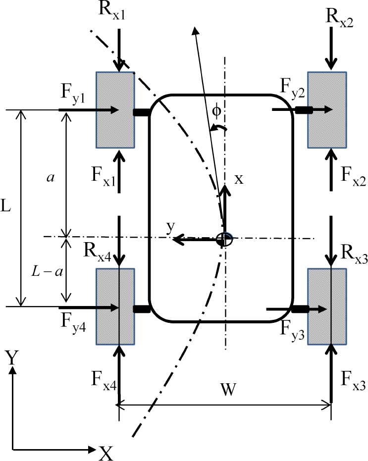
A schematic model of the mobile platform
Based on the schematic model that is illustrated in Figure 2, the equation of motion can be obtained as:

where F xi is the tractive force at the contact point of the wheel, R xi is the longitudinal resistive force of the wheel, and F yi is the lateral force at the contact point of the wheel [7]. By considering friction coefficients (μ x , μ y ), the resistive force, lateral force and resistive moment at the CM can be calculated as:

The dynamic model of the platform with generalized coordinates, q=(X, Y, ϕ) can be expressed as a matrix form by:
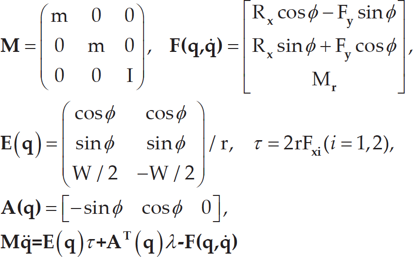
where r is the wheel radius, τ are the torques at the left and right side of the motors to the drive wheels, the matrix


where
Since each side of the front and rear wheels is connected with V-belts, the four-wheel skid-steering platform can be considered as a two-wheel differential driven mobile platform. In particular, for instantaneous motion, kinematic equivalences between the four-wheel skid-steer and ideal wheeled differential drive vehicles can be considered [14]. The equation of motion for the platform with nonholonomic constraint can be presented as:

From Equation (4) and Equation (6), the state feedback control law becomes:

where
In order to carry out the cleaning process of the duct surfaces while driving the platform, the upper brush arm was designed to move through the surfaces of the rectangular duct. The sweeping movement of the upper brush arm can shift the CM of the platform, which also affects the yaw moment of the platform. Therefore, in order to control the heading angle and follow a reference trajectory, torques of the traction motor should be determined by considering the dynamic shift of the CM point (see Figure 3).

Simplified model of the upper rotating brush arm
The shifting position of the CM can be calculated as:
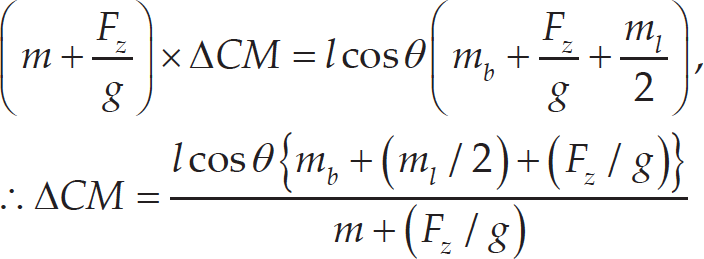
where l is the length of the brush arm, ΔCM is the shifted distance of the CM in the lateral direction, m b is the mass of the rotating brush, and m is the overall mass except for the brush and arm. The rotation angle of the brush arm, θ, ranges from 0 to 180 [deg], as shown in Figure 3. As the CM changes, the yaw moment of the platform is changed. Thus, the resistive moment of Equation (2) can be recalculated as follows:

By considering the changeable CM position, the detailed steering motion of the platform is modelled and illustrated in Figure 4.
In the skid-steering control, the velocity difference between the left and right wheels is required to implement the skid-steering function of the platform along the curving track. In particular, when the CM shifts, as depicted in Figure 4, the yaw moment change and velocity changes are required for accurate steering control of the platform.
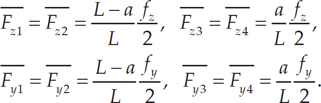
During the cleaning process with the upper brush arm, external forces are exerted to the platform wheels [15, 16]. The force on the front brush was considered as a part of the platform weight because it is a non-moving static load. The external forces acting on the upper brush can be calculated with the contact model between the rotating brush and the plane, as shown in Figure 5. However, as it is not possible to measure the exact value of the friction force acting between the brush and the duct surface, the model in Figure 5 assumed a friction coefficient as a random value. As a result, the vertical force


where θ t = tan−1 {(D y −r b −r)/(D x /2)} when the duct size is D x × D y , r b is the radius of the brush, and F s is the pressurizing force applied by the upper arm. The vertical forces and lateral forces acting on the wheels can be calculated as:

Steering motion model with the shifting centre of mass (CM) of the platform
Therefore, the force matrix

where

A schematic of forces exerted on duct surfaces from the brushing arm and mobile platform
In order to control the platform as a given trajectory, the dynamic disturbances that are caused by moving the CM and brush interaction forces need to be considered to determine the control inputs and motor torques. A simple trajectory tracking controller that can reduce the effect of disturbances is presented, as follows. Since the perfect velocity tracking method requires no disturbance conditions or having a complete dynamic model for the system, the integrator backstepping method in controlling the model of a nonholonomic system can be used [10]. The error vector,

The derivative of the platform target velocity,

where ˙c can apply to the concept of the perfect velocity tracking to obtain the control input, which is expressed in Equation (7). However, it is impossible for an actual platform to be controlled at a target velocity without a feedbacking velocity error in the trajectory tracking. Therefore, the control input can be expressed with feedback of the platform velocity as the following:

where

A control scheme for the suggested trajectory tracking control
Additionally, using the Lyapunov function, the error vector (
Figure 6 shows the control flow scheme, which integrates the backstepping method and the I-PD controller for the trajectory tracking control of the platform. The I-PD controller can be converted to a discrete form and expressed as in Equation (17). The new control input can be obtained by integrating the I-PD controller and the backstepping controller of the velocity, as expressed in Equation (18):
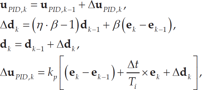

where derivative gain is 1/η = 10, effective D-gain (β) is
Based on the analytical model of the controller, the performance of the trajectory tracking controller was verified through MATLAB. The mobile platform that was used in the analysis has dimensions that are based on the prototype of the duct-cleaning robot in Figure 1: length (L=0.3[m]), distance from the CM to the front wheel (a=0.15[m]), distance between the left and right wheels (w=0.23[m]), wheel radius (r=0.05[m]), mass moment of inertia (I=0.19[kgm2]), total mass of the cleaning robot (moverall = 7.823[kg]), and top surface tool mass (mbrush + m link = 1.777[kg]). To consider the pressing effect of the brush arm under an unknown friction, a random function within 20 per cent of the pressurizing force was applied to the wheel of the platform model as a disturbance input. The brush cleaning forces were selected and simulated between 50N and 150N, as in Figure 8 and 10.
Two reference trajectories with straight line tracking and curved line tracking were used in the analysis. Firstly, in the straight line tracking analysis, the reference trajectory was configured as x
r
= v
r
t, y
r
= v
r
t. The heading angle of the given trajectory was ϕ = 45° and the reference velocity was v
r
√2. The friction coefficient of the wheel was set to μ
x
= 0.9, μ
y
= 0.1, and different coefficients were used for the longitudinal (x) and lateral direction (y). Through the iterative simulation, the gains of the backstepping controller were obtained as k1 = 10, k2 = 9, k3 = 5,
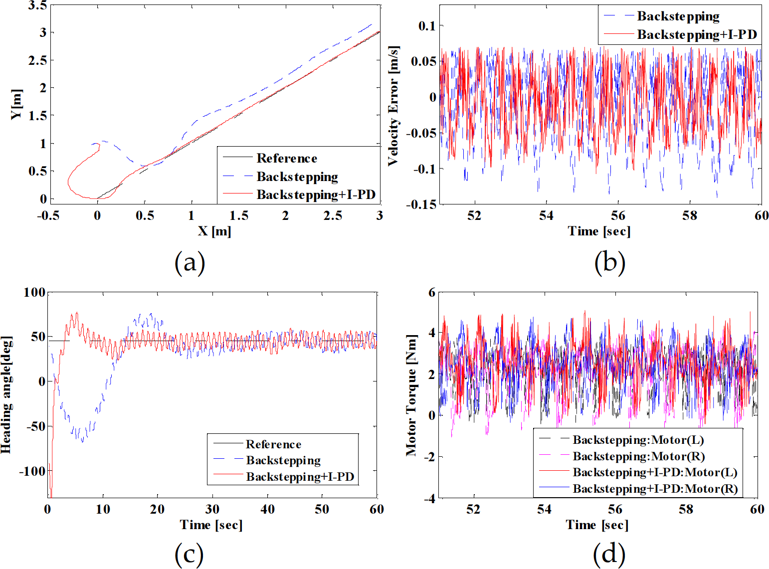
Simulation results with a straight line trajectory tracking, a) trajectory, b) error in velocity, c) heading angle, and d) input motor torque
The results in Figure 7(a) show the position error of the platform during 60 seconds. Applying the I-PD and backstepping controller reduced the steady state error. Figure 7(b) shows the error between the target velocity and the platform velocity during the simulation time. The heading angle of the platform, which resulted in Figure 7(c), also has converged to 45 degrees, as was set in the reference line trajectory. The interactive forces between the brush arm and duct surface caused the fluctuation errors in the heading angle. Figure 7(d) shows the motor torque changes that were applied to both sides of the platform wheels. Additionally, Figure 8 compares the position errors of the backstepping controller and the integrated I-PD controller with backstepping. The integrated I-PD and backstepping controller greatly reduced the lateral position errors.

Error comparison in the straight line trajectory tracking with various brush loads
Additionally, the simulation was conducted with a curved reference trajectory, x
r
= v
r
t, y
r
= 0.5sin(2πt/60) to investigate the tracking performance in steering movements. The gains of the backstepping controller could be obtained through iterative simulation, as k1=9, k2=40, k3=0,

Simulation results with a curved line trajectory tracking, a) trajectory, b) error in velocity, c) heading angle, and d) input motor torque

Error comparison in the curved line trajectory tracking with various brush loads
This research presents a new controller that enables stable trajectory tracking of an autonomous mobile platform for duct cleaning. Additionally, this research modelled and analysed the static and dynamic forces including the disturbances between the rotating brush and the duct surface. By considering the wheel frictions and interactive forces between the rotating brush and duct surface, the integrated trajectory tracking controller was proposed. In particular, the backstepping technique was adopted for assigning the estimated target velocity. Nevertheless, under dynamic pressure changes in the brush arm, there were steady state errors that cannot be ignored. Therefore, by integrating a relatively simple I-PD controller with the backstepping, the overall position errors could be reduced and provide stable trajectory tracking control under dynamic disturbances.
Footnotes
7.
This research was carried out as part of the project (Development of PM removing vehicle), partially funded by the Ministry of Land, Infrastructure and Transport and Ministry of Science, ICT and Future Planning in Korea.